EP0138226A2 - Mobilfunkkommunikationssystem - Google Patents
Mobilfunkkommunikationssystem Download PDFInfo
- Publication number
- EP0138226A2 EP0138226A2 EP84112476A EP84112476A EP0138226A2 EP 0138226 A2 EP0138226 A2 EP 0138226A2 EP 84112476 A EP84112476 A EP 84112476A EP 84112476 A EP84112476 A EP 84112476A EP 0138226 A2 EP0138226 A2 EP 0138226A2
- Authority
- EP
- European Patent Office
- Prior art keywords
- base station
- mobile
- mobile stations
- mobile radio
- operating power
- Prior art date
- Legal status (The legal status is an assumption and is not a legal conclusion. Google has not performed a legal analysis and makes no representation as to the accuracy of the status listed.)
- Withdrawn
Links
Images

Classifications
-
- H—ELECTRICITY
- H04—ELECTRIC COMMUNICATION TECHNIQUE
- H04W—WIRELESS COMMUNICATION NETWORKS
- H04W52/00—Power management, e.g. Transmission Power Control [TPC] or power classes
- H04W52/02—Power saving arrangements
- H04W52/0209—Power saving arrangements in terminal devices
- H04W52/0212—Power saving arrangements in terminal devices managed by the network, e.g. network or access point is leader and terminal is follower
- H04W52/0219—Power saving arrangements in terminal devices managed by the network, e.g. network or access point is leader and terminal is follower where the power saving management affects multiple terminals
-
- Y—GENERAL TAGGING OF NEW TECHNOLOGICAL DEVELOPMENTS; GENERAL TAGGING OF CROSS-SECTIONAL TECHNOLOGIES SPANNING OVER SEVERAL SECTIONS OF THE IPC; TECHNICAL SUBJECTS COVERED BY FORMER USPC CROSS-REFERENCE ART COLLECTIONS [XRACs] AND DIGESTS
- Y02—TECHNOLOGIES OR APPLICATIONS FOR MITIGATION OR ADAPTATION AGAINST CLIMATE CHANGE
- Y02D—CLIMATE CHANGE MITIGATION TECHNOLOGIES IN INFORMATION AND COMMUNICATION TECHNOLOGIES [ICT], I.E. INFORMATION AND COMMUNICATION TECHNOLOGIES AIMING AT THE REDUCTION OF THEIR OWN ENERGY USE
- Y02D30/00—Reducing energy consumption in communication networks
- Y02D30/70—Reducing energy consumption in communication networks in wireless communication networks
Definitions
- This invention relates to a mobile radio communication system in which a plurality of mobile subscribers commonly utilize a limited number of channels, and more particularly a power saving type or voice-operated mobile radio apparatus suitable for radio telephone system.
- a transmission electromagnetic wave is continuously sent out of the mobile apparatus irrespective of presence or absence of a voice signal.
- a car in which the mobile apparatus is installed may substantially goes out of the service area of one base station, for example, or enter into a tunnel or a underground garage where electromagnetic wave does not reach and the car does not leave the garage in a predetermined interval.
- a speech termination signal may not be received at the base station owing to a multi-path fading phenomenon or the like thus resulting in a failure of speech termination processing.
- the base station forcibly releases a channel now being used in response to a failure to detect the reception of electromagnetic wave for a predetermined interval, for example, 5 to 30 seconds, and assigns the released channel to another subscriber after another predetermined interval (generally 10 to 60 seconds).
- a predetermined interval for example, 5 to 30 seconds
- assigns the released channel to another subscriber after another predetermined interval (generally 10 to 60 seconds).
- the radio frequency is utilized efficiently in the mobile telephone system.
- a power saving or voice-operated type mobile radio transmission apparatus has been proposed.
- the power consumption can be saved efficiently.
- this power saving type transmission apparatus does not transmit electromagnetic wave.during reception of the speech from the other party. Accordingly, when this power saving type transmission apparatus is incorporated into the mobile telephone system of the type described above, a channel now being used will be forcibly released if the speech from the other party continues so long a period of time that the aforementioned 5 to 30 second predetermiend interval has elapsed.
- the base station may be conceived to construct the base station such that it stops the performance of forcibly releasing the channel being utilized only when such a power saving type mobile radio transmission apparatus is used, but to do so, it is necessary to greatly change the construction of mobile communication system. Moreover, there is no countermeasure when a power saving type mobile radio apparatus goes out of the service area.
- a mobile radio communication system wherein one base station and a plurality of mobile stations are located in a zone, the base station and the mobile stations communicate with each other by commonly utilizing a relatively small number of radio channels, and the base station is controlled to forcibly release a channel being used when it does not receive electromagnetic wave from a transmitting apparatus, comprised of a modulator and a transmission amplifier, of any one of the mobile stations under communication for a predetermined interval, characterized in that transmitting apparatus of each mobile station comprises means for supplying operating power to the transmission amplifier only when transmission information is inputted to the modulator modulating a carrier wave with the transmission information, and means for temporarily supplying the operating power to the transmission amplifier at an interval shorter than the predetermined interval.
- a timer is provided for a power saving type mobile radio pparatus for interrupting the transmitted electromagnetic other than the transmission of a voice signal.
- a prior art power saving type mobile radio transmission apparatus shown in Fig. 1 Before describing the preferred embodiments of this invention, a prior art power saving type mobile radio transmission apparatus shown in Fig. 1 will first be described.
- the output of a microphone 1 is amplified by an amplifier 2 and then modulates a carrier wave at a modulator 3.
- the modulated carrier wave is amplified by a radio frequency (RF) power amplifier 4 and then sent to an antenna 5.
- RF radio frequency
- a portion of the output of the microphone 1 branches to a voice input detector 6 which detects the fact that the output level of the microphone exceeds a predetermined level. Only when the voice input detector 6 produces an output, a transistor 7 is turned ON to supply DC power to the RF power amplifier 4.
- this apparatus has a number of problems. The invention contemplates elimination of such problems.
- the circuit elements identical to those shown in Fig. 1 are designated by the same reference numerals.
- the voice output of the microphone 1 is applied to the amplifier 2.
- the output thereof is supplied to the antenna 5 through modulator 3, and amplifier 4 in the same manner as in Fig. 1.
- the output of the voice detector 6 is applied to the base electrode of a transistor 7 with its emitter electrode supplied with a bias voltage, and collector electrode connected to the control input terminal of the RF power amplifier 4.
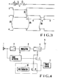
- the feature of this invention lies in the provision of a timer unit bounded by dot and dash lines shown in Fig. 2. More particularly, the output of the voice input detector 6 is supplied to a timer 8 with its output connected to the base electrode of a transistor 9. The emitter electrode of transistor 9 is supplied with the DC power source 11, while the collector electrode is connected to the control input terminal of the RF power amplifier together with the collector electrode of transistor 7.
- Fig. 3 is a timing chart showing signals a, b, c and d appearing in the Fig. 2 circuit.
- the microphone 1, amplifier 2, and modulator 3 operate in the same manner as those shown in Fig. 1.
- a voice signal represented by the signal a is detected by the voice detector 6, the transistor 7 is turned ON as shown at (A) in Fig. 3 to cause the RF power amplifier 4 to start transmitting the modulated carrier wave through antenna 5.
- the transistor 7 is turned OFF as shown at (B) in Fig. 3, thus rendering inoperative the RF power amplifier 4.
- the timer 8 is started, producing the signal c having an ON time of t 2 seconds and an OFF time of t 3 seconds. After lapse of t 2 seconds, the timer 8 becomes OFF for t 3 seconds and then begins counting of t 2 seconds. As shown at (D) in Fig. 3, the output of timer 8 is applied to the base electrode of transistor 9 to enable the RF power amplifier 4. In this manner, unless the voice input is inputted, the RF power amplifier 4 outputs intermittently the output to be transmitted for t 3 seconds following each period of t 2 seconds.
- the interval of t 2 seconds is set to be shorter than the 5 to 30 second predetermined time of the base station (a timer controlled time of the base station) and that the value of t 3 seconds is made long sufficient to allow the reciever in the base station to detect the electromagnetic wave.
- the timer 8 shown in Fig. 2 is replaced by a multivibrator 10 having an ON time of t 2 seconds and an OFF time of t 3 seconds.
- This modification operates regardless of the control of a voice signal as shown in Fig. 3.
- the radio apparatus is made operative to radiate electromagnetic wave for a minimum 0(zero) second and a maximum of t 2 seconds after the transmitter has been rendered OFF because of the disappearance of the voice signal.
- the power consumption increases to slightly exceed that of the power saving type mobile radio apparatus shown in Fig. 2, but the same advantageous effect can be obtained.
- a timer having an ON time slightly shorter than the forcible release time of a channel being used and an OFF time necessary for the base station to detect arrival of the electromagnetic wave from the mobile radio apparatus so that the electromagnetic wave is sent out intermittently even when there is no voice input, with the result that.the base station will not forcibly release the channel being used.
- the power saving type radio apparatus can be introduced without modifying the existing mobile radio telephone system, whereby an economic sytem can be realized which is capable of efficiently utilizing frequency and elongating the battery life of the mobile apparatus.
- the electromagnetic wave may be controlled by controlling the DC power supplied to the modulator or the oscillator of the modulator, instead of the DC power to RF power amplifier.
Landscapes
- Engineering & Computer Science (AREA)
- Computer Networks & Wireless Communication (AREA)
- Signal Processing (AREA)
- Mobile Radio Communication Systems (AREA)
Applications Claiming Priority (2)
| Application Number | Priority Date | Filing Date | Title |
|---|---|---|---|
| JP194591/83 | 1983-10-17 | ||
| JP58194591A JPS6085633A (ja) | 1983-10-17 | 1983-10-17 | 移動無線通信方式 |
Publications (2)
| Publication Number | Publication Date |
|---|---|
| EP0138226A2 true EP0138226A2 (de) | 1985-04-24 |
| EP0138226A3 EP0138226A3 (de) | 1987-07-22 |
Family
ID=16327088
Family Applications (1)
| Application Number | Title | Priority Date | Filing Date |
|---|---|---|---|
| EP84112476A Withdrawn EP0138226A3 (de) | 1983-10-17 | 1984-10-16 | Mobilfunkkommunikationssystem |
Country Status (3)
| Country | Link |
|---|---|
| EP (1) | EP0138226A3 (de) |
| JP (1) | JPS6085633A (de) |
| AU (1) | AU3427484A (de) |
Cited By (1)
| Publication number | Priority date | Publication date | Assignee | Title |
|---|---|---|---|---|
| WO1996033585A1 (en) * | 1995-04-21 | 1996-10-24 | Ericsson Inc. | Battery-powered radio transceiver with improved battery life and method of operation |
Families Citing this family (8)
| Publication number | Priority date | Publication date | Assignee | Title |
|---|---|---|---|---|
| JPS60256235A (ja) * | 1984-06-01 | 1985-12-17 | Nec Corp | 単一搬送波単一通話路多重通信方式 |
| JPH0644716B2 (ja) * | 1984-08-14 | 1994-06-08 | 日本電気株式会社 | 無線通信装置 |
| JPH0787609B2 (ja) * | 1986-06-13 | 1995-09-20 | 日本電気株式会社 | 無線電話装置 |
| US4837800A (en) * | 1988-03-18 | 1989-06-06 | Motorola, Inc. | Cellular data telephone system and cellular data telephone therefor |
| JPH0453315A (ja) * | 1990-06-20 | 1992-02-20 | Seiko Instr Inc | 携帯用無線装置 |
| JPH04334216A (ja) * | 1991-05-10 | 1992-11-20 | Osaka Gas Co Ltd | デジタル無線網の回線保持方法 |
| JPH04334217A (ja) * | 1991-05-10 | 1992-11-20 | Osaka Gas Co Ltd | デジタル無線網の回線保持装置 |
| WO2005057037A1 (en) * | 2003-12-09 | 2005-06-23 | Litens Automotive Partnership | Spring travel limitor for overrunning decoupler |
Family Cites Families (2)
| Publication number | Priority date | Publication date | Assignee | Title |
|---|---|---|---|---|
| US4119800A (en) * | 1977-02-28 | 1978-10-10 | Port-A-Phone, Inc. | Radio-telephone interconnection system |
| DE2862297D1 (en) * | 1978-11-11 | 1983-08-25 | Int Mobile Machines | Portable radiotelephone system |
-
1983
- 1983-10-17 JP JP58194591A patent/JPS6085633A/ja active Pending
-
1984
- 1984-10-16 EP EP84112476A patent/EP0138226A3/de not_active Withdrawn
- 1984-10-16 AU AU34274/84A patent/AU3427484A/en not_active Abandoned
Cited By (3)
| Publication number | Priority date | Publication date | Assignee | Title |
|---|---|---|---|---|
| WO1996033585A1 (en) * | 1995-04-21 | 1996-10-24 | Ericsson Inc. | Battery-powered radio transceiver with improved battery life and method of operation |
| AU706197B2 (en) * | 1995-04-21 | 1999-06-10 | Ericsson Inc. | Battery-powered radio transceiver with improved battery life and method of operation |
| CN1088317C (zh) * | 1995-04-21 | 2002-07-24 | 艾利森公司 | 具有改善电池寿命的电池供电的无线电收发信机和操作方法 |
Also Published As
| Publication number | Publication date |
|---|---|
| AU3427484A (en) | 1985-04-26 |
| JPS6085633A (ja) | 1985-05-15 |
| EP0138226A3 (de) | 1987-07-22 |
Similar Documents
| Publication | Publication Date | Title |
|---|---|---|
| US5031231A (en) | Mobile telephone station with power saving circuit | |
| US3962553A (en) | Portable telephone system having a battery saver feature | |
| US6122083A (en) | Mobile communication system having a small base station and equipment for its system | |
| CN1067537A (zh) | 检测和校正功率放大器的饱和的方法和装置 | |
| DE69622847D1 (de) | Empfang in mobilen endgeräten durch einen kanal in direkter betriebsweise | |
| US4802201A (en) | Control system of a radio telephone apparatus | |
| JPH0545102B2 (de) | ||
| EP0138226A2 (de) | Mobilfunkkommunikationssystem | |
| EP0041289A1 (de) | Sende-Empfangs-Gerät | |
| US3825829A (en) | Radio system employing simultaneously triggered pulse repeaters | |
| IL44474A (en) | Battery saving system for duplex radio system | |
| US7050838B1 (en) | Portable terminal device with power saving information processing | |
| US2851591A (en) | Selective calling wireless transmission system | |
| US4062016A (en) | Simultaneous telecommunication between radio stations | |
| US4706243A (en) | Single-channel-per-carrier communication system including a voice-activated transmission power controller | |
| US2572235A (en) | Multichannel intermodulation interference reduction radio communication system | |
| JPS61107826A (ja) | 移動無線通信方式 | |
| JP3060974B2 (ja) | 割込通信制御装置 | |
| KR100249203B1 (ko) | 이동통신 단말기 | |
| JP3006114B2 (ja) | 地球局装置の電源制御方式 | |
| JPH09135200A (ja) | 衛星通信地球局の送信制御方式 | |
| JPH05347580A (ja) | 移動通信システム | |
| JPS6130822A (ja) | 自動割込通信装置 | |
| KR19990080425A (ko) | 역 알림 서비스를 위한 송.수신장치 및 그 제어방법 | |
| JP2858024B2 (ja) | 無線デイジタル電話システム |
Legal Events
| Date | Code | Title | Description |
|---|---|---|---|
| PUAI | Public reference made under article 153(3) epc to a published international application that has entered the european phase |
Free format text: ORIGINAL CODE: 0009012 |
|
| 17P | Request for examination filed |
Effective date: 19841016 |
|
| AK | Designated contracting states |
Designated state(s): DE FR GB NL |
|
| PUAL | Search report despatched |
Free format text: ORIGINAL CODE: 0009013 |
|
| AK | Designated contracting states |
Kind code of ref document: A3 Designated state(s): DE FR GB NL |
|
| STAA | Information on the status of an ep patent application or granted ep patent |
Free format text: STATUS: THE APPLICATION IS DEEMED TO BE WITHDRAWN |
|
| 18D | Application deemed to be withdrawn |
Effective date: 19861103 |
|
| RIN1 | Information on inventor provided before grant (corrected) |
Inventor name: KAI, TOMOKAZU |