EP0138308B1 - Industrieroboter mit direktem, koaxialem Motorantrieb - Google Patents
Industrieroboter mit direktem, koaxialem Motorantrieb Download PDFInfo
- Publication number
- EP0138308B1 EP0138308B1 EP84305040A EP84305040A EP0138308B1 EP 0138308 B1 EP0138308 B1 EP 0138308B1 EP 84305040 A EP84305040 A EP 84305040A EP 84305040 A EP84305040 A EP 84305040A EP 0138308 B1 EP0138308 B1 EP 0138308B1
- Authority
- EP
- European Patent Office
- Prior art keywords
- drive unit
- axis
- base component
- component
- drive
- Prior art date
- Legal status (The legal status is an assumption and is not a legal conclusion. Google has not performed a legal analysis and makes no representation as to the accuracy of the status listed.)
- Expired
Links
Images


Classifications
-
- B—PERFORMING OPERATIONS; TRANSPORTING
- B25—HAND TOOLS; PORTABLE POWER-DRIVEN TOOLS; MANIPULATORS
- B25J—MANIPULATORS; CHAMBERS PROVIDED WITH MANIPULATION DEVICES
- B25J9/00—Program-controlled manipulators
- B25J9/02—Program-controlled manipulators characterised by movement of the arms, e.g. cartesian coordinate type
- B25J9/04—Program-controlled manipulators characterised by movement of the arms, e.g. cartesian coordinate type by rotating at least one arm, excluding the head movement itself, e.g. cylindrical coordinate type or polar coordinate type
- B25J9/046—Revolute coordinate type
-
- B—PERFORMING OPERATIONS; TRANSPORTING
- B25—HAND TOOLS; PORTABLE POWER-DRIVEN TOOLS; MANIPULATORS
- B25J—MANIPULATORS; CHAMBERS PROVIDED WITH MANIPULATION DEVICES
- B25J17/00—Joints
- B25J17/02—Wrist joints
- B25J17/0241—One-dimensional joints
-
- B—PERFORMING OPERATIONS; TRANSPORTING
- B25—HAND TOOLS; PORTABLE POWER-DRIVEN TOOLS; MANIPULATORS
- B25J—MANIPULATORS; CHAMBERS PROVIDED WITH MANIPULATION DEVICES
- B25J9/00—Program-controlled manipulators
- B25J9/08—Program-controlled manipulators characterised by modular constructions
-
- B—PERFORMING OPERATIONS; TRANSPORTING
- B25—HAND TOOLS; PORTABLE POWER-DRIVEN TOOLS; MANIPULATORS
- B25J—MANIPULATORS; CHAMBERS PROVIDED WITH MANIPULATION DEVICES
- B25J9/00—Program-controlled manipulators
- B25J9/10—Program-controlled manipulators characterised by positioning means for manipulator elements
- B25J9/12—Program-controlled manipulators characterised by positioning means for manipulator elements electric
- B25J9/126—Rotary actuators
-
- H—ELECTRICITY
- H02—GENERATION; CONVERSION OR DISTRIBUTION OF ELECTRIC POWER
- H02K—DYNAMO-ELECTRIC MACHINES
- H02K37/00—Motors with rotor rotating step by step and without interrupter or commutator driven by the rotor, e.g. stepping motors
-
- Y—GENERAL TAGGING OF NEW TECHNOLOGICAL DEVELOPMENTS; GENERAL TAGGING OF CROSS-SECTIONAL TECHNOLOGIES SPANNING OVER SEVERAL SECTIONS OF THE IPC; TECHNICAL SUBJECTS COVERED BY FORMER USPC CROSS-REFERENCE ART COLLECTIONS [XRACs] AND DIGESTS
- Y10—TECHNICAL SUBJECTS COVERED BY FORMER USPC
- Y10T—TECHNICAL SUBJECTS COVERED BY FORMER US CLASSIFICATION
- Y10T74/00—Machine element or mechanism
- Y10T74/19—Gearing
- Y10T74/19023—Plural power paths to and/or from gearing
- Y10T74/19051—Single driven plural drives
- Y10T74/19065—Aligned
Definitions
- the present invention relates to an industrial robot of the type designed as a replacement for human labor in performing repetitive, hazardous, or tiring work.
- Industrial robots of the described type typically have the capability of moving through six axes of movement to manipulate objects, parts, or tools through variable programmed motions for the performance of a variety of tasks.
- Reprogrammable robots are also available which incorporate a computer and microprocessor whereby the robot may be taught to move from point to point using a portable teaching box or the like.
- Conventional industrial robots of the type adapted to move through six revolute axes typically include a primary drive system which provides for movement about three primary axes, and an outer arm assembly which is adapted to move a hand assembly through three additional axes of movement.
- the drive system for each of the three primary axes of movement included a drive motor and a torque converting drive train composed of gears, drive rods, and the like.
- drive trains are not only expensive, but they introduce limitations on the accuracy of the movements by reason of unavoidable inaccuracies in their design and assembly, and "backlash" which is inherent in the system.
- the drive trains require substantial alignment and assembly time during fabrication or repair, they increase the opportunity for failure resulting from wear, broken teeth or other components, and they are relatively heavy and bulky.
- an industrial robot having at least three controlled axes of movement, and comprising first, second, and third drive units with each drive unit comprising a base component, a secondary component relatively rotatably mounted with respect to the base component to define a rotational axis of movement, and means interconnecting said secondary components of each of said three drive units so that the first drive unit defines a first axis of movement (A), and said second and third drive units define second and third coaxial axes of movement (B) and characterised by an electrical motor having a rotor disposed coaxially about the associated rotational axis and being directly fixed to one of either said base component or said secondary component, and a stator disposed coaxially about the associated rotational axis and being directly fixed to the other of said base component or secondary component.
- the invention includes an industrial robot having at least three controlled axes of movement, and a support member, a first drive unit having a base component fixedly mounted to said support member, a secondary component relatively rotatably mounted with respect to said base component to define a first axis (A), and drive means for relatively rotating said base component and secondary component about said first axis, a second drive unit having a base component, a secondary component relatively rotatably mounted with respect to its base component to define a second axis (B), means directly fixedly mounting said secondary component of said second drive unit to said secondary component of said first drive unit such that the second axis is non parallel to said first axis, output means directly fixed to said base component of said second drive unit and aligned coaxially with said second axis, and drive means for relatively rotating said base component and secondary component of said second drive unit about said second axis, a third drive unit having a base component, a secondary component relatively rotatably mounted with respect to its base component to define a further axis
- the invention includes an industrial robot having a plurality of controlled axes of movement, and comprising a support member, a first drive unit having a base component and a secondary component, said base component being relatively rotatably mounted with respect to said secondary component to define a central axis (B), means directly fixedly mounting said secondary component of said first drive unit to said support member, output shaft means directly fixed to said base component and aligned coaxially with said central axis, and drive means for rotating said base component about said central axis, and a further drive unit having a tubular base component and a secondary component, said base component being rotatably mounted with respect to its secondary component for rotation about said central axis and being coaxially disposed about said output shaft means, means directly fixedly mounting said secondary component of said further drive unit to said support member, tubular output means directly fixed to said base component of said further drive unit and aligned coaxially about said output shaft means of said first drive unit, and drive means for rotating said base component of said further drive unit about said central
- an industrial robot embodying the features of the present invention is illustrated generally at 10.
- the robot 10 is adapted to move through six axes of movement, and it comprises a main frame 12 which includes a support stand 13, with the stand defining a generally vertical axes A.
- a waist 14 is rotatable with respect to the stand and defines a generally horizontal axis B which is perpendicular to and intersects the axis A.
- a first or inner arm 15 is rotatable with respect to the waist about the horizontal axis B, and a second or outer arm 16 is rotatable with respect to the inner arm about a second horizontal axis C, which is parallel to and laterally spaced from the axis B.
- a hand assembly 18 including a gripper 19 is mounted at one end of the outer arm 16, and is adapted to move through three additional axes of movement, in the manner further described in applicant's copending United States application Serial No. 443,156, and corresponding EPO application No. 83300373.4 (EP-A-0086054).
- the main frame of the robot includes a control box 20 mounted adjacent the stand 13 for housing the electronic controls for the various drive motors of the robot.
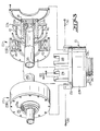
- the robot 10 further includes a first drive unit 21 having a tubular base component 21 a and a secondary component 21 b which is rotatable with respect to the base component about the axis A.
- the base component 21 a is fixedly connected to the support stand 13 by releasable coupling means, which includes a circular flange 24 on the support stand, and a mating circular flange 21c integrally formed on the base component.
- a releasable coupler in the form of a split band 25 of generally V-shaped configuration encloses the periphery of the mating flanges to maintain the assembly of the components.
- the split band 25 incorporates a conventional release mechanism for selectively opening and tightening the band circumferentially about the periphery of the abutting flanges, and so as to selectively retain the flanges in assembled relation.
- a split band of this type is further described in applicant's above noted co-pending applications.
- a carriage 26 is fixed to the secondary component 21b b of the first drive unit 21 by bolts 27, and the carriage includes upright parallel brackets 28 which mount a second drive unit 22 and a third drive unit 23, and which collectively form a part of the waist 14 of the robot.
- the three units are of substantially identical configuration, and this standardization greatly simplifies the design, construction, and repair of the overall apparatus, and promotes the interchangeability of parts.
- the second and third drive units 22, 23 each include a tubular base component 22a, 23a and a secondary component 22b, 23b which is relatively rotatable about the axis of its base component.
- the secondary components 22b, 23b are fixed to the brackets 28 of the carriage 26 and thus to each other by removable bolts 30 or the like, and such that the second and third drive units are coaxially disposed about the axis B. Also, the second and third drive units are disposed in opposite orientations as will be apparent from Figure 4.
- the third drive unit 23 includes output means in the form of a mounting flange 23c integrally formed at the end of the tubular base component 23a, and a tubular extension 32 which is releaseably connected to the flange 23c by means of a V-band coupler 25 of the type described above.
- the tubular extension 32 includes a second flange 35 at its other end for the purposes to be described.
- the extension mounts a number of weights 36 which serve to counterbalance the weight of the outer arm 16 during its movement about the axis B.
- the second drive unit 22 includes output means in the form of a mounting flange 22c, and an elongate drive shaft 38 which extends coaxially through the base component 23a of the third drive unit and the extension 32.
- the drive shaft 38 includes a flange 39 at one end which is releaseably joined to the flange 22c of the base component of the second drive unit by another coupler 25.
- Each of the three drive units includes drive means for relatively rotating its base component and secondary component about the associated axis of movement.
- the drive means for the unit 21 includes an electrical stepping motor which comprises a rotor 40 disposed coaxially about the rotational axis A and which is directly fixed to the base component 21 a.
- the electrical motor includes a stator 42 which is disposed coaxially about the rotational axis A and is directly fixed to the secondary component 21 b.
- the drive means for each of the other drive units 22 and 23 includes a like motor and which has its rotor and stator coaxially disposed about the axis of movement.
- Electrical stepping motors of the described type are per se well known in the art and are operated by discrete electrical pulses which are fed in a sequential manner from a suitable switching control system. For every pulse fed to the motor, the motor rotates a fixed angle, and thus the number of pulses fed to the motor determines the rotational angle the motor will make. In order to obtain verification that the motor has in fact rotated, it is also common to mount a shaft encoder on the output of the motor, which senses the angular position of the motor and produces a verification signal upon each step having been taken. In the illustrated embodiment, this position sensing means takes the form of the laminate stacks 44. As one specific suitable example, a stepping motor may be utilized with the present invention which is manufactured by Motornetics Corporation of Santa Rosa, California, and which is designed for 125,000 pulses or steps per revolution.
- the inner arm 15 of the robot comprises a casing 50, which has a mounting flange 51 at one end which is releaseably connected to the flange 35 of the extension 32 by still another coupler 25, which also conforms to the structure of the other couplers utilized on the robot.
- the shaft 38 from the second drive unit extends coaxially through the flange 51 of the casing, and mounts a sprocket 54 at the free end thereof.
- a second shaft 55 is rotatably mounted at the other end of the casing 50, and is disposed coaxially about the horizontal axis C, which is parallel to and laterally spaced from the horizontal axis B.
- the shaft 55 includes an integral flange 56 which mates with a flange 57 on the casing 58 of the outer arm 16, and the two flanges are joined by a further V-band coupler 25.
- the second shaft 55 mounts a sprocket 61 within the casing 50 of the inner arm, and a flexible endless toothed belt 62 is operatively entrained about the sprockets.
- the rotation of the base component 22a of the second drive unit 22 is transmitted to the outer arm 16, causing the outer arm to rotate about the axis C.
- the rotation of the base component 23a of the third drive unit 23 is transmitted to the inner arm 15, causing the inner arm to rotate about the axis B.
Landscapes
- Engineering & Computer Science (AREA)
- Robotics (AREA)
- Mechanical Engineering (AREA)
- Power Engineering (AREA)
- Manipulator (AREA)
- Control Of Electric Motors In General (AREA)
- Control Of Multiple Motors (AREA)
Claims (10)
Priority Applications (1)
| Application Number | Priority Date | Filing Date | Title |
|---|---|---|---|
| AT84305040T ATE33220T1 (de) | 1983-08-19 | 1984-07-24 | Industrieroboter mit direktem, koaxialem motorantrieb. |
Applications Claiming Priority (2)
| Application Number | Priority Date | Filing Date | Title |
|---|---|---|---|
| US06/524,839 US4552505A (en) | 1982-11-19 | 1983-08-19 | Industrial robot having direct coaxial motor drive |
| US524839 | 1983-08-19 |
Publications (2)
| Publication Number | Publication Date |
|---|---|
| EP0138308A1 EP0138308A1 (de) | 1985-04-24 |
| EP0138308B1 true EP0138308B1 (de) | 1988-03-30 |
Family
ID=24090869
Family Applications (1)
| Application Number | Title | Priority Date | Filing Date |
|---|---|---|---|
| EP84305040A Expired EP0138308B1 (de) | 1983-08-19 | 1984-07-24 | Industrieroboter mit direktem, koaxialem Motorantrieb |
Country Status (6)
| Country | Link |
|---|---|
| US (1) | US4552505A (de) |
| EP (1) | EP0138308B1 (de) |
| JP (1) | JPS60123279A (de) |
| AT (1) | ATE33220T1 (de) |
| CA (1) | CA1239164A (de) |
| DE (1) | DE3470126D1 (de) |
Families Citing this family (30)
| Publication number | Priority date | Publication date | Assignee | Title |
|---|---|---|---|---|
| US4699563A (en) * | 1984-05-31 | 1987-10-13 | Seiko Instruments & Electronics Ltd. | Horizontal articulated robot |
| US4702668A (en) * | 1985-01-24 | 1987-10-27 | Adept Technology, Inc. | Direct drive robotic system |
| DE3518104A1 (de) * | 1985-05-21 | 1986-11-27 | Arnold Müller GmbH & Co KG, 7312 Kirchheim | Antriebsvorrichtung zur erzeugung von schwenkbewegungen und weiteren bewegungen |
| FR2582630B1 (fr) * | 1985-05-28 | 1991-04-05 | Pouyaud Andre | Dispositif de prelevement pneumatique de matieres granuleuses ou pulverulentes |
| US4973215A (en) * | 1986-02-18 | 1990-11-27 | Robotics Research Corporation | Industrial robot with servo |
| US5096364A (en) * | 1986-04-28 | 1992-03-17 | Varian Associates, Inc. | Wafer arm handler mechanism |
| US4768918A (en) * | 1986-06-13 | 1988-09-06 | American Cimflex Corporation | Industrial robot having counterbalanced arms |
| US4728252A (en) * | 1986-08-22 | 1988-03-01 | Lam Research Corporation | Wafer transport mechanism |
| JPS63162176A (ja) * | 1986-12-24 | 1988-07-05 | フアナツク株式会社 | 水平関節型ロボツトの第1ア−ム構造 |
| JPS63191585A (ja) * | 1987-01-31 | 1988-08-09 | フアナツク株式会社 | ダイレクト・ドライブ型多関節ロボツト |
| US4775289A (en) * | 1987-09-25 | 1988-10-04 | Regents Of The University Of Minnesota | Statically-balanced direct-drive robot arm |
| FR2633487B1 (fr) * | 1988-07-04 | 1991-04-05 | Tout Pour Le Grain Sa | Dispositif de prelevement de matieres granuleuses ou pulverulentes |
| US5102280A (en) * | 1989-03-07 | 1992-04-07 | Ade Corporation | Robot prealigner |
| GB8907270D0 (en) * | 1989-03-31 | 1989-05-17 | Teamleader Robotics Ltd | Linear gantry robot |
| DE4001885A1 (de) * | 1990-01-23 | 1991-07-25 | Kuka Schweissanlagen & Roboter | Mehrachsiger industrieroboter |
| JPH0779840A (ja) * | 1993-09-10 | 1995-03-28 | Tokai Rubber Ind Ltd | 重量物搭載板回動装置 |
| SE515130C2 (sv) * | 1995-02-24 | 2001-06-11 | Abb Ab | Robotutrustning |
| US5746565A (en) * | 1996-01-22 | 1998-05-05 | Integrated Solutions, Inc. | Robotic wafer handler |
| KR101214723B1 (ko) * | 2004-06-24 | 2012-12-24 | 아이로보트 코퍼레이션 | 자동 로봇 장치용의 원격 제어 스케줄러 및 방법 |
| US20070125480A1 (en) * | 2005-12-01 | 2007-06-07 | Henthorne David A | Synchronous drive and method for tire cord application |
| US7657769B2 (en) | 2007-01-08 | 2010-02-02 | Marcy M Scott | N-way synchronization of data |
| US8444631B2 (en) * | 2007-06-14 | 2013-05-21 | Macdonald Dettwiler & Associates Inc | Surgical manipulator |
| US11471020B2 (en) | 2011-04-29 | 2022-10-18 | Irobot Corporation | Robotic vacuum cleaning system |
| GB2505127B (en) | 2011-04-29 | 2015-02-11 | Irobot Corp | An autonomous mobile robot |
| US10512384B2 (en) | 2016-12-15 | 2019-12-24 | Irobot Corporation | Cleaning roller for cleaning robots |
| US10595624B2 (en) | 2017-07-25 | 2020-03-24 | Irobot Corporation | Cleaning roller for cleaning robots |
| JP6875348B2 (ja) * | 2018-10-17 | 2021-05-26 | ファナック株式会社 | ロボットおよび第1アーム部材 |
| US11109727B2 (en) | 2019-02-28 | 2021-09-07 | Irobot Corporation | Cleaning rollers for cleaning robots |
| CN110000808B (zh) * | 2019-04-28 | 2022-04-26 | 深圳市汇川技术股份有限公司 | 机器人关节结构及机器人关节结构的装配方法 |
| TW202219420A (zh) * | 2020-11-03 | 2022-05-16 | 崔文德 | 球座標轉向機構 |
Family Cites Families (27)
| Publication number | Priority date | Publication date | Assignee | Title |
|---|---|---|---|---|
| US2459253A (en) * | 1944-11-29 | 1949-01-18 | Air Reduction | Reproducing apparatus |
| FR1266080A (fr) * | 1960-07-30 | 1961-07-07 | Zaklady Wytworcze Glosnikow To | Manipulateur télécommandé électriquement à distance |
| US3146386A (en) * | 1963-07-10 | 1964-08-25 | Gerber Scientific Instr Co | Stepping motor drive |
| US3559008A (en) * | 1967-06-09 | 1971-01-26 | Siemens Ag | Voltage proportional speed control of the output of a differential gear connected to two motors utilizing a pulse width modulator control |
| FR2183584B1 (de) * | 1972-05-10 | 1974-09-27 | Commissariat Energie Atomique | |
| DE2224349C3 (de) * | 1972-05-18 | 1978-11-23 | Pfaff Pietzsch Industrieroboter Gmbh, 7505 Ettlingen | Manipulator |
| DE2228598A1 (de) * | 1972-06-12 | 1974-01-03 | Jens Dr Rer Nat Geerk | Anthropomorpher manipulator |
| US3834555A (en) * | 1972-12-04 | 1974-09-10 | Budd Co | Article transfer apparatus |
| US3985238A (en) * | 1973-03-17 | 1976-10-12 | Daikin Kogyo Co., Ltd. | Industrial robot |
| DE2530261C2 (de) * | 1974-10-22 | 1986-10-23 | Asea S.p.A., Mailand/Milano | Programmiereinrichtung für einen Manipulator |
| US3922930A (en) * | 1974-12-23 | 1975-12-02 | Nasa | Remotely operable articulated manipulator |
| US4181465A (en) * | 1975-02-13 | 1980-01-01 | Aktiebolaget Electrolux | Apparatus utilizing magnetic means for transferring articles to and from predetermined positions |
| US4068763A (en) * | 1976-07-26 | 1978-01-17 | Nasa | Wrist joint assembly |
| US4062455A (en) * | 1976-11-22 | 1977-12-13 | Flatau Carl R | Remote manipulator |
| US4068536A (en) * | 1976-12-23 | 1978-01-17 | Cincinnati Milacron Inc. | Manipulator |
| SU763082A1 (ru) * | 1977-07-01 | 1980-09-15 | Предприятие П/Я Р-6930 | Манипул тор модульного типа |
| CS212433B1 (en) * | 1977-12-06 | 1982-03-26 | Zdenko Stanicek | Electrically driven mechanic arm of the industrial robot |
| DE2754609A1 (de) * | 1977-12-08 | 1979-06-13 | Karlsruhe Augsburg Iweka | Antriebsaggregat fuer die handachsen eines handhabungsgeraetes |
| US4289996A (en) * | 1978-08-29 | 1981-09-15 | Frazer Nash Limited | Actuators |
| DE2908523A1 (de) * | 1979-03-05 | 1981-01-29 | Jungheinrich Unternehmensverw | Automatisches arbeitsgeraet |
| US4246661A (en) * | 1979-03-15 | 1981-01-27 | The Boeing Company | Digitally-controlled artificial hand |
| GB2058009B (en) * | 1979-09-13 | 1983-07-27 | Atomic Energy Authority Uk | Manipulators |
| US4445184A (en) * | 1980-07-19 | 1984-04-24 | Shin Meiwa Industry Co., Ltd. | Articulated robot |
| CA1209172A (en) * | 1981-10-23 | 1986-08-05 | Peter E. Chance | Robotic manipulator arm |
| US4459898A (en) * | 1981-12-09 | 1984-07-17 | Nordson Corporation | Streamlined multi-axis robot wrist assembly with partially enclosed hydraulic and electrical lines to minimize the wrist envelope |
| US4636138A (en) * | 1982-02-05 | 1987-01-13 | American Robot Corporation | Industrial robot |
| US4398110A (en) * | 1982-05-05 | 1983-08-09 | Westinghouse Electric Corp. | Harmonic electric actuator |
-
1983
- 1983-08-19 US US06/524,839 patent/US4552505A/en not_active Expired - Fee Related
-
1984
- 1984-06-25 CA CA000457343A patent/CA1239164A/en not_active Expired
- 1984-07-24 AT AT84305040T patent/ATE33220T1/de not_active IP Right Cessation
- 1984-07-24 EP EP84305040A patent/EP0138308B1/de not_active Expired
- 1984-07-24 DE DE8484305040T patent/DE3470126D1/de not_active Expired
- 1984-08-17 JP JP59172324A patent/JPS60123279A/ja active Pending
Also Published As
| Publication number | Publication date |
|---|---|
| EP0138308A1 (de) | 1985-04-24 |
| ATE33220T1 (de) | 1988-04-15 |
| DE3470126D1 (en) | 1988-05-05 |
| JPS60123279A (ja) | 1985-07-01 |
| CA1239164A (en) | 1988-07-12 |
| US4552505A (en) | 1985-11-12 |
Similar Documents
| Publication | Publication Date | Title |
|---|---|---|
| US4552505A (en) | Industrial robot having direct coaxial motor drive | |
| US4645409A (en) | Outer arm assembly for industrial robot | |
| US4636138A (en) | Industrial robot | |
| US4671732A (en) | Industrial robot | |
| CA1065365A (en) | Remote manipulator | |
| EP0249232B1 (de) | Handgelenk für Roboter | |
| EP0048904B1 (de) | Industrieroboter | |
| US5872892A (en) | Process and apparatus for imparting linear motion to tooling attached to the end of a manipulator device having two different length arms | |
| EP0105656A2 (de) | Industrieroboter | |
| EP0102082B1 (de) | Industrieroboter | |
| JPH0583353B2 (de) | ||
| JPH03154791A (ja) | ロボット用多関節アーム | |
| US4424473A (en) | Drive apparatus for an industrial robot | |
| EP3784446B1 (de) | Parallelkinematikroboter | |
| US20200331151A1 (en) | Robot arm with a robot-hand drive device | |
| US4761114A (en) | Articulated head for an industrial robot and a robot equipped with a head of this type | |
| EP0112099A1 (de) | Roboterglied | |
| US4489624A (en) | Triaxial hinge for robots, handling apparatus and the like | |
| EP0128544B1 (de) | Gelenkanordnung zwischen Verbindungsteilen, insbesondere für einen Industrieroboterarm | |
| US4768918A (en) | Industrial robot having counterbalanced arms | |
| JPH0750412B2 (ja) | ロボツトの制御装置 | |
| CN217168525U (zh) | 组装式六轴机械臂 | |
| JP3051868B2 (ja) | ロボットの手首機構 | |
| CN213206480U (zh) | 一种模块化电机传动组件及机械臂 | |
| JPH0512119B2 (de) |
Legal Events
| Date | Code | Title | Description |
|---|---|---|---|
| PUAI | Public reference made under article 153(3) epc to a published international application that has entered the european phase |
Free format text: ORIGINAL CODE: 0009012 |
|
| AK | Designated contracting states |
Designated state(s): AT BE CH DE FR GB IT LI LU NL SE |
|
| 17P | Request for examination filed |
Effective date: 19851016 |
|
| 17Q | First examination report despatched |
Effective date: 19860730 |
|
| R17C | First examination report despatched (corrected) |
Effective date: 19870204 |
|
| RAP1 | Party data changed (applicant data changed or rights of an application transferred) |
Owner name: AMERICAN CIMFLEX CORPORATION |
|
| GRAA | (expected) grant |
Free format text: ORIGINAL CODE: 0009210 |
|
| AK | Designated contracting states |
Kind code of ref document: B1 Designated state(s): AT BE CH DE FR GB IT LI LU NL SE |
|
| PG25 | Lapsed in a contracting state [announced via postgrant information from national office to epo] |
Ref country code: NL Effective date: 19880330 Ref country code: LI Effective date: 19880330 Ref country code: IT Free format text: LAPSE BECAUSE OF FAILURE TO SUBMIT A TRANSLATION OF THE DESCRIPTION OR TO PAY THE FEE WITHIN THE PRESCRIBED TIME-LIMIT;WARNING: LAPSES OF ITALIAN PATENTS WITH EFFECTIVE DATE BEFORE 2007 MAY HAVE OCCURRED AT ANY TIME BEFORE 2007. THE CORRECT EFFECTIVE DATE MAY BE DIFFERENT FROM THE ONE RECORDED. Effective date: 19880330 Ref country code: CH Effective date: 19880330 Ref country code: BE Effective date: 19880330 Ref country code: AT Effective date: 19880330 |
|
| REF | Corresponds to: |
Ref document number: 33220 Country of ref document: AT Date of ref document: 19880415 Kind code of ref document: T |
|
| PG25 | Lapsed in a contracting state [announced via postgrant information from national office to epo] |
Ref country code: SE Effective date: 19880331 |
|
| REF | Corresponds to: |
Ref document number: 3470126 Country of ref document: DE Date of ref document: 19880505 |
|
| REG | Reference to a national code |
Ref country code: CH Ref legal event code: PL |
|
| ET | Fr: translation filed | ||
| PG25 | Lapsed in a contracting state [announced via postgrant information from national office to epo] |
Ref country code: LU Free format text: LAPSE BECAUSE OF NON-PAYMENT OF DUE FEES Effective date: 19880731 |
|
| NLV1 | Nl: lapsed or annulled due to failure to fulfill the requirements of art. 29p and 29m of the patents act | ||
| PLBE | No opposition filed within time limit |
Free format text: ORIGINAL CODE: 0009261 |
|
| STAA | Information on the status of an ep patent application or granted ep patent |
Free format text: STATUS: NO OPPOSITION FILED WITHIN TIME LIMIT |
|
| 26N | No opposition filed | ||
| PGFP | Annual fee paid to national office [announced via postgrant information from national office to epo] |
Ref country code: GB Payment date: 19900718 Year of fee payment: 7 |
|
| PGFP | Annual fee paid to national office [announced via postgrant information from national office to epo] |
Ref country code: FR Payment date: 19900727 Year of fee payment: 7 |
|
| PGFP | Annual fee paid to national office [announced via postgrant information from national office to epo] |
Ref country code: DE Payment date: 19900822 Year of fee payment: 7 |
|
| PG25 | Lapsed in a contracting state [announced via postgrant information from national office to epo] |
Ref country code: GB Effective date: 19910724 |
|
| GBPC | Gb: european patent ceased through non-payment of renewal fee | ||
| PG25 | Lapsed in a contracting state [announced via postgrant information from national office to epo] |
Ref country code: FR Effective date: 19920331 |
|
| PG25 | Lapsed in a contracting state [announced via postgrant information from national office to epo] |
Ref country code: DE Effective date: 19920401 |
|
| REG | Reference to a national code |
Ref country code: FR Ref legal event code: ST |