EP0138310A1 - Pompe à anneau liquide avec élément d'orifice conique ou cylindrique - Google Patents
Pompe à anneau liquide avec élément d'orifice conique ou cylindrique Download PDFInfo
- Publication number
- EP0138310A1 EP0138310A1 EP84305166A EP84305166A EP0138310A1 EP 0138310 A1 EP0138310 A1 EP 0138310A1 EP 84305166 A EP84305166 A EP 84305166A EP 84305166 A EP84305166 A EP 84305166A EP 0138310 A1 EP0138310 A1 EP 0138310A1
- Authority
- EP
- European Patent Office
- Prior art keywords
- port
- pump
- vent
- conduit
- rotor
- Prior art date
- Legal status (The legal status is an assumption and is not a legal conclusion. Google has not performed a legal analysis and makes no representation as to the accuracy of the status listed.)
- Granted
Links
- 239000007788 liquid Substances 0.000 title claims abstract description 75
- 230000006835 compression Effects 0.000 claims abstract description 55
- 238000007906 compression Methods 0.000 claims abstract description 55
- 238000005086 pumping Methods 0.000 claims abstract description 46
- 239000012530 fluid Substances 0.000 claims description 10
- 238000007599 discharging Methods 0.000 claims 1
- 230000001737 promoting effect Effects 0.000 claims 1
- 238000013461 design Methods 0.000 description 5
- 238000013022 venting Methods 0.000 description 3
- 239000000203 mixture Substances 0.000 description 2
- 230000003134 recirculating effect Effects 0.000 description 2
- XLYOFNOQVPJJNP-UHFFFAOYSA-N water Substances O XLYOFNOQVPJJNP-UHFFFAOYSA-N 0.000 description 2
- 230000001668 ameliorated effect Effects 0.000 description 1
- 238000013459 approach Methods 0.000 description 1
- 230000000712 assembly Effects 0.000 description 1
- 238000000429 assembly Methods 0.000 description 1
- 125000004122 cyclic group Chemical group 0.000 description 1
- 230000002349 favourable effect Effects 0.000 description 1
- 230000001788 irregular Effects 0.000 description 1
- 238000012423 maintenance Methods 0.000 description 1
- 238000012986 modification Methods 0.000 description 1
- 230000004048 modification Effects 0.000 description 1
Images


Classifications
-
- F—MECHANICAL ENGINEERING; LIGHTING; HEATING; WEAPONS; BLASTING
- F04—POSITIVE - DISPLACEMENT MACHINES FOR LIQUIDS; PUMPS FOR LIQUIDS OR ELASTIC FLUIDS
- F04C—ROTARY-PISTON, OR OSCILLATING-PISTON, POSITIVE-DISPLACEMENT MACHINES FOR LIQUIDS; ROTARY-PISTON, OR OSCILLATING-PISTON, POSITIVE-DISPLACEMENT PUMPS
- F04C19/00—Rotary-piston pumps with fluid ring or the like, specially adapted for elastic fluids
- F04C19/005—Details concerning the admission or discharge
- F04C19/008—Port members in the form of conical or cylindrical pieces situated in the centre of the impeller
Definitions
- This invention relates to liquid ring pumps, and more particularly to liquid ring pumps having conical or cylindrical port members.
- a liquid ring.pump having conical port members is shown in Jennings U.S. patent 3,154,240.
- the principal components of this pump are (1) a cylindrical housing; (2) a rotatable shaft mounted eccentrically in the housing; (3) a bladed rotor fixedly mounted on the shaft; (4) two frusto-conical port members coaxial with the shaft, each port member extending into an annular recess in a respective one of the opposite ends of the rotor and having (a) an intake port for admitting to the rotor the gas, vapor, or gas-vapor mixture to be pumped (hereinafter referred to generically as gas) and (b) a discharge port for conveying compressed gas from the rotor; and (5) a head member at each end of the pump for conveying gas between the associated port member and appropriate pump inlets and.
- a quantity of pumping liquid e.g., water
- the rotor blades engage the pumping liquid and form it into an annular ring concentric with the housing.
- the liquid ring cooperates with the rotor blades to form a plurality of gas pumping chambers, each chamber being bounded by (1) two adjacent rotor blades, (2) the adjacent portion of the rotor hub or the conical port member, and (3) the adjacent portion of the inner surface of the liquid ring. Because the rotor is eccentric to the housing, these pumping chambers vary in size in a cyclic fashion as the rotor rotates.
- the pumping chambers are expanding. This is the gas intake zone of the pump, and the intake ports are therefore located so as to communicate with the pumping chambers in this zone.
- the pumping chambers are contracting. This is the gas compression zone of the pump, and the discharge ports are therefore located so as to communicate with the pumping chambers in this zone.
- Liquid ring pumps are typically designed to provide a particular compression ratio or a relatively narrow range of compression ratios for extended periods of time.
- the power required to operate the pump may increase substantially.
- very high pressures may occur in the compression zone of the pump prior to the discharge port. This overcompression of the gas being pumped increases the power necessary to drive the pump until the normal compression ratio is achieved.
- the pump In order to meet these occasional increased power requirements, the pump must be equipped with a motor larger than would otherwise be necessary. This is uneconomical, and it is clearly desirable to minimize the amount by which the power requirements of the pump increase under off-normal operating conditions.
- liquid ring pumps Another consideration in the design of liquid ring pumps is that the higher the compression ratio the pump is designed to achieve, the more sensitive the pump becomes to off-normal operating conditions. Typically, if a liquid ring pump is designed to achieve a very high compression ratio, it is subject to very severe overcompression problems at lower than normal compression ratios. Similarly, unless a liquid ring pump is designed to achieve a high compression ratio (in which case it typically operates less efficiently at lower compression ratios), it generally cannot achieve such high compression ratios at all.
- liquid ring pumps especially those designed for operation at relatively low speeds and low compression ratios, is that such pumps may exhibit instability manifested by excessive vibration and loss of pumping ability when subjected to compression ratios higher than the design compression ratio. This condition may be ameliorated by increasing the flow of pumping liquid to the pump. But this approach usually increases pump operating cost and and may only shift the point at which the pump becomes unstable.
- a conically or cylindrically ported liquid ring pump in which, in addition to the intake and discharge ports, the port member has a vent-recirculation port located after the intake port but before the discharge port in the direction of rotor rotation.
- the head of the pump also defines a sump chamber for normally retaining a quantity of pumping liquid.
- the sump chamber communicates with the gas outlet of the pump at a location above the normal sump liquid level.
- the vent-recirculation port is connected to the sump chamber at a location below the normal sump liquid level.
- the vent-recirculation port acts as a vent or an additional discharge port for allowing gas to reach the pump outlet via the sump chamber. This substantially prevents overcompression of the gas at low compression ratios.
- the vent-recirculation port may be essentially inoperative, being substantially closed off by the pumping liquid in the sump chamber.
- pumping liquid from the sump chamber is pulled back into the liquid ring via the vent-recirculation port, which then acts as a recirculation path.
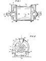
- illustrative liquid, ring pump 10 includes cylindrical housing 12 having two head members 14a and 14b at respective opposite ends of housing 12. Because the two ends of the pump are substantially mirror images of one another, only the left-hand end of the pump as viewed in Figure 1 will be shown and described in full detail herein.
- Each head 14a, 14b has a pump inlet 16a, 16b, respectively.
- Each head 14a, 14b also has a primary pump outlet 18a, 18b, respectively, and an alternate pump outlet 18x, 18y, respectively.
- either outlet can be used in each head to suit the convenience of the user.
- the outlet which is not being used is covered by a cover plate.
- Gas to be pumped is supplied to inlets 16 via conduits (not shown). After compression by the pump, the gas exits via outlets 18 and is conveyed away by other conduits (also not shown).
- Shaft 20 is eccentrically mounted for rotation in housing 12. In other words, the rotational axis of shaft 20 is parallel to but laterally offset from the central axis of cylindrical housing 12. Shaft 20 passes through each head 14 and is supported for rotation by bearing assemblies 22 fixed to the heads. Shaft 20 is rotated by a suitable pump motor (not shown) in the direction indicated by arrow 50.
- a rotor 30 Fixedly mounted on shaft 20 inside housing 12 is a rotor 30 having a plurality of blades 32 extending radially outward from hub 34.
- the cross sectional shape of each blade and the typical circumferential spacing of the blades around the rotor hub are illustrated in Figure 15. Although hooked slightly near their outer tips, blades 32 may be thought of as substantially planar, the plane of each blade being parallel to the axis of shaft 20.
- Blades 32 are substantially longer parallel to shaft 20 than hub 34. Blades 32 are divided in half lengthwise and also stiffened by annular divider 36, which extends radially outward from hub 34 all the way to the outer tips of the blades. Each half of each blade has three lengthwise parts: a first part 32a where the blade is connected to hub 34; a second part 32b where the blade is radially spaced from shaft 20 and unsupported by any connection to the adjacent blades; and a third part 32c where the blade is also radially spaced from shaft 20 but connected to annular end shroud 38.
- Annular end shroud 38 is a substantially planar toroidal or washer-shaped member which extends from an inner circle immediately adjacent to port member 40 (described below) to an outer circle adjacent the outer tips of blades 32. End shroud 38 stiffens the otherwise unsupported ends of blades 32 and also closes off the ends of the gas pumping chambers formed between adjacent blades. Although only one end of rotor 30 is visible in Figure 3, it will be understood that there is an end shroud 38 at each end of the rotor.
- each blade 32 is radially spaced from shaft 20 because the above-described second and third portions 32b and 32c of each blade 32 are radially spaced from shaft 20, the result is an annular space around shaft 20 adjacent each end of the rotor.
- An annular port member 40 is fixedly mounted on each of head members 14 and projects into this annular space at the adjacent end of rotor 30.
- each of port members 40 is an annular structure surrounding the adjacent portion of shaft 20.
- a quantity of pumping liquid such as water is maintained in housing 12. Any pumping liquid which is lost during operation of the apparatus is made up by fresh pumping liquid supplied to the pump via conduit 24 ( Figure 2).
- blades 32 engage the pumping liquid and cause it to form an annular ring substantially concentric with housing 12.
- the liquid ring is typically quite turbulent so that its inner surface is irregular, the approximate location of this inner surface is represented by broken lines 52 in Figure 3. Because rotor 30 is eccentric to housing 12, rotor blades 32 (which always engage the liquid ring to some degree) extend farther into the liquid ring on one side of the pump than on the other side.
- each port member 40 includes an intake port 42 which is located near the inner edges of rotor blade portions 32b adjacent the intake zone of the pump. Port member 40 also defines an intake conduit 44 which connects to an intake conduit 64 in the adjacent head member 14. Intake conduit 64 leads to the associated pump inlet 16. Gas supplied to pump inlet 16 is therefore drawn into the intake zone of the pump via conduits 64 and 44 and intake port 42.
- each port member 40 further includes a discharge port 46 which is located near the edges of rotor blade portions 32b adjacent the compression zone of the pump.
- Port member 40 also defines a discharge conduit 48 which connects to a discharge conduit 68 in the adjacent head member 14.
- Discharge conduit 68 leads to the associated pump outlet 18 (see Figure 4). Gas compressed by the pump is therefore discharged from the compression zone of the pump via discharge port 46 and discharge conduits 48 and 68.
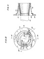
- port member 40 is better seen in Figures 10-14.
- Figure 10 is an end view of left-hand port member 40 as seen from the adjacent head member 14a.
- Figure 12 is an opposite end view of the same port member. Proceeding counterclockwise around the structure shown in Figure 10, intake conduit 44 occupies approximately one half of the interior of the port member. Intake port 42 spans a major portion of conduit 44.
- vent conduit 70 which communicates with vent port 72 in the conical outer surface of the port member. The operation of vent port 72 will be described in greater detail below, but it should be noted here that vent port 72 is located near the inner edges of rotor blade portions 32b adjacent an initial portion of the compression zone of the pump.
- vent-recirculation conduit 74 which communicates with vent-recirculation port 76.
- Vent-recirculation port 76 is located near the inner edges of rotor blade portions 32b adjacent an intermediate portion of the compression zone of the pump.
- discharge port 46 and associated discharge conduit 48 The next portion of port member 40 is discharge port 46 and associated discharge conduit 48.
- the final portion of port member 40 is pumping liquid conduit 78 for conveying pumping liquid from conduit 24 to a point adjacent the rotor hub to replenish the liquid ring and to also provide a gas seal at that point in the pump.
- Each of port member conduits 44, 70, 74, 48, and 78 is completely separate from the other conduits in port member 40. However, each of these port member conduits communicates with a corresponding conduit in the adjacent head member 14.
- Figure 6 shows the port member side of the head member 14a which is intended for connection to the port member 40 shown in Figures 10-14. Proceeding clockwise around the central portion of the structure shown in Figure 6, intake conduit 64 is designed to communicate with intake conduit 44 in port member 40. Vent conduit 80 is designed to communicate with vent conduit 70 in port member 40. Vent-recirculation conduit 84 is designed to communicate with vent-recirculation conduit 74 in port member 40. Discharge conduit 68 is designed to communicate with discharge conduit 48 in port member 40. And pumping liquid conduit 88 is designed to communicate with pumping liquid conduit 78 in port member 40.
- intake conduit 64 can be seen in broken lines in Figure 4 to be a relatively large semi-cylindrical chamber which communicates with pump inlet 16a at the top of the pump (see also Figures 3 and 8).
- Vent conduit 80 is also visible in broken lines in Figure 4 as a truncated wedge shaped chamber which leads to check valve assembly 90 (see also Figures 7 and 9).
- Check valve assembly 90 includes ball-type check valve 92 between vent conduit 80 and vent-recirculation conduit 84. When the pressure in vent conduit 80 is greater than the pressure in vent-recirculation conduit 84, check valve 92 opens to allow fluid to flow from conduit 80 to conduit 84.
- Check valve assembly 90 has a removable cover plate 94 for facilitating maintenance of check valve 92.
- the check valve ball is guided by three parallel pins 96 (only two of which are visible in Figure 9) which are mounted on cover plate 94 and which slope downwardly away from the cover plate toward the wall between conduits 80 and 84.
- One or more additional horizontal pins 98 are mounted on the wall between conduits 80 and 84 to temporarily support the check valve ball during removal or replacement of cover plate 94.
- Vent-recirculation conduit 84 is also visible in broken lines in Figure 4.
- the portion of conduit 84 closest to port member 40 is another truncated wedge shaped chamber which communicates with the lower portion of check valve assembly 90 (see also Figure 9).
- vent-recirculation conduit 84 runs vertically downward and has an approximately square cross section as can be seen in Figure 5 (see also Figure 9).
- vent-recirculation conduit 84 makes a right angle turn and runs horizontally across the pump (see Figures 4, 5, and 8).
- vent-recirculation conduit 84 opens out into the bottom of a sump chamber 100 formed in head member 14 to the right of baffle member 102.
- Sump chamber 100 communicates with discharge conduit 68 and is designed to collect and retain at least some of the pumping liquid which is normally discharged from the liquid ring with the compressed gas. Although conditions in discharge conduit 68 and sump chamber 100 are typically very turbulent so that the boundary between the liquid and gas phases is poorly defined, vent-recirculation conduit 84 communicates with sump chamber 100 at a point which is at least nominally below the normal level of pumping liquid in the sump chamber. It should be noted that baffle member 102 does not pass through vent-recirculation conduit 84.
- Discharge conduit 68 is visible in both dotted and solid lines in Figure 4. The portion of conduit 68 to the right of baffle member 102 as viewed in Figure 4 communicates with sump chamber 100 as mentioned above. To the left of baffle member 102, conduit 68 communicates with pump outlet 18a and alternate pump outlet 18x.
- Pumping liquid conduit 88 is also visible in broken lines in Figure 4 and is another truncated wedge shaped chamber which communicates with pumping liquid supply conduit 24.
- gas enters the pump via pump inlet 16 and flows through conduits 64 and 44 into rotor 30 in the intake zone of the pump.
- the make-up stream of pumping liquid flows from conduit 24, through conduits 88 and 78, around the small end of conical port member 40, and into the liquid ring via the gas pumping chambers formed between adjacent pairs of rotor blades 32.
- the gas reaches the final discharge pressure of the pump soon after entering the compression zone of the pump. Accordingly, some of the gas exits from the rotor via vent port 72 and flows through conduits 70 and 80, through check valve 92, and into conduit 84. From conduit 84 this gas flows through sump chamber 100 and discharge conduit 68 to pump outlet 18. Vent port 72 and the associated conduits therefore relieve the early build-up of gas pressure in the compression zone of the pump at low compression ratios.
- vent-recirculation port 76 and the associated conduits therefore further relieve the early build-up of gas pressure in the compression zone of the pump at low compression ratios.
- the final portion of the gas in rotor 30 again reaches the final discharge pressure of the pump adjacent discharge port 46. Accordingly, the final portion of the gas (and some pumping liquid) exits from the rotor via discharge port 46. This fluid flows through conduits 48 and 68 and exits from the pump via pump outlet 18.
- the gas does not reach the final discharge pressure of the pump until after passing vent port 72. Accordingly, the gas pressure in conduit 80 is less than the pressure in conduit 84 and check valve 92 is closed. Vent port 72 is therefore effectively closed. The gas does reach the final discharge pressure of the pump adjacent vent-recirculation port 76. Accordingly, a portion of the gas exits from rotor 30 via vent-recirculation port 76. This gas flows through conduits 74 and 84, through sump chamber 100, and into conduit 68, which conveys it to pump outlet 18. Vent-recirculation port 76 and the associated conduits therefore act as a vent for relieving early build-up of gas pressure in the pump when operating at intermediate compression ratios.
- vent-recirculation port 76 and the associated conduits operate to automatically increase the volume of the liquid ring when the pump reaches high compression ratios. This extends the operating range of the pump to compression ratios substantially higher than could otherwise be attained.
- Recirculation of pumping liquid in the pump helps reduce the necessity for a high flow of make-up pumping liquid. The fact that the volume of gas in the recirculated fluid flow is reduced by the substantial fraction of pumping liquid in that flow greatly reduces the inefficiency associated with recirculating gas in a liquid ring pump.
- vent port 72 and/or vent-recirculation port 76 prevent wasteful overcompression of the gas in the rotor of the pump, thereby reducing the power required to operate the pump at these compression ratios.
- vent port 72 is closed and vent-recirculation port 76 is also either effectively closed or recirculating fluid including a high proportion of pumping liquid, thereby extending the operating range of the pump to compression ratios substantially higher than could otherwise be attained.
- the present invention also enables conically or cylindrically ported liquid ring pumps to better respond to operating condition fluctuations. For example, if the flow of gas to the pump suddenly increases, or if a large slug of liquid suddenly enters the pump via pump inlet 16, vent port 72 and/or vent-recirculation port 76 instantly and automatically begin to vent rotor 30 to prevent overcompression in the pump.
- vent port 72 and associated conduits 70 and 80 and check valve assembly 90 can be eliminated as shown in Figure 16.
- the pump of Figure 16 can be the same as shown and described above, except that it will not have the early venting provided by vent port 72 and the associated elements.
- Vent-recirculation port 76 can be provided with a nozzle shape as shown in Figure 17.
- This nozzle shape is smoothly convergent in the favorable or inward flow direction and is square-edged in the unfavorable or outward flow direction. This shape promotes inward flow (i.e., venting), and somewhat inhibits outward flow (i.e., recirculation). This may be desirable so that port 76, which is of fixed size, provides a larger volume of venting flow than recirculation flow.
- Vent-recirculation port 76 can be angled relative to the adjacent radial axis 110 of the pump as shown in Figure 18.
- vent-recirculation port 76 is inclined in the direction of rotor rotation from conduit 74 toward the adjacent portion of rotor 30. This gives the recirculated fluid re-entering rotor 30 via port 76 a component of velocity parallel to the direction of motion of the adjacent rotor blades 32. This in turn reduces energy losses in the pump due to reorienting the flow of recirculated fluid so that it is parallel to the direction of motion of the adjacent rotor blades.
Landscapes
- Engineering & Computer Science (AREA)
- Mechanical Engineering (AREA)
- General Engineering & Computer Science (AREA)
- Rotary Pumps (AREA)
- Jet Pumps And Other Pumps (AREA)
- Closures For Containers (AREA)
- Reciprocating Pumps (AREA)
- Applications Or Details Of Rotary Compressors (AREA)
Applications Claiming Priority (2)
| Application Number | Priority Date | Filing Date | Title |
|---|---|---|---|
| US06/521,449 US4498844A (en) | 1983-08-08 | 1983-08-08 | Liquid ring pump with conical or cylindrical port member |
| US521449 | 1983-08-08 |
Publications (2)
| Publication Number | Publication Date |
|---|---|
| EP0138310A1 true EP0138310A1 (fr) | 1985-04-24 |
| EP0138310B1 EP0138310B1 (fr) | 1987-11-04 |
Family
ID=24076778
Family Applications (1)
| Application Number | Title | Priority Date | Filing Date |
|---|---|---|---|
| EP84305166A Expired EP0138310B1 (fr) | 1983-08-08 | 1984-07-30 | Pompe à anneau liquide avec élément d'orifice conique ou cylindrique |
Country Status (10)
| Country | Link |
|---|---|
| US (1) | US4498844A (fr) |
| EP (1) | EP0138310B1 (fr) |
| JP (1) | JPS6060292A (fr) |
| AU (1) | AU562164B2 (fr) |
| BR (1) | BR8403947A (fr) |
| CA (1) | CA1233148A (fr) |
| DE (1) | DE3429085C2 (fr) |
| FI (1) | FI76628C (fr) |
| SE (1) | SE456028B (fr) |
| ZA (1) | ZA845797B (fr) |
Cited By (1)
| Publication number | Priority date | Publication date | Assignee | Title |
|---|---|---|---|---|
| WO1989012168A1 (fr) * | 1988-06-08 | 1989-12-14 | Pentamo Oy | Compresseur a anneau liquide |
Families Citing this family (31)
| Publication number | Priority date | Publication date | Assignee | Title |
|---|---|---|---|---|
| USD293912S (en) | 1986-01-17 | 1988-01-26 | Copeland Corporation | Oil pump |
| USD293913S (en) | 1986-01-17 | 1988-01-26 | Copeland Corporation | Oil pump |
| US4747752A (en) * | 1987-04-20 | 1988-05-31 | Somarakis, Inc. | Sealing and dynamic operation of a liquid ring pump |
| US4914921A (en) * | 1988-08-16 | 1990-04-10 | Cbi Research Corporation | Refrigeration method and apparatus using aqueous liquid sealed compressor |
| EP0401397B1 (fr) * | 1989-06-05 | 1992-11-19 | Siemens Aktiengesellschaft | Compresseur à anneau liquide |
| US5100300A (en) * | 1990-12-28 | 1992-03-31 | The Nash Engineering Company | Liquid ring pumps having rotating lobe liners with end walls |
| US5246348A (en) * | 1992-05-14 | 1993-09-21 | Vooner Vacuum Pumps, Inc. | Liquid ring vacuum pump-compressor with double function of liquid ring with separate sources |
| US5356268A (en) * | 1993-09-29 | 1994-10-18 | The Nash Engineering Company | Check valve structures for liquid ring pumps |
| DE9406597U1 (de) * | 1994-04-20 | 1995-08-24 | Sihi GmbH & Co KG, 25524 Itzehoe | Flüssigkeitsringgaspumpe |
| CN1071004C (zh) * | 1995-08-21 | 2001-09-12 | 西门子公司 | 环形液体压缩机 |
| US5961295A (en) * | 1997-07-03 | 1999-10-05 | The Nash Engineering Company | Mixed flow liquid ring pumps |
| DE19847681C1 (de) * | 1998-10-15 | 2000-06-15 | Siemens Ag | Flüssigkeitsringpumpe |
| US6390768B1 (en) | 1999-03-22 | 2002-05-21 | David Muhs | Pump impeller and related components |
| US6315524B1 (en) | 1999-03-22 | 2001-11-13 | David Muhs | Pump system with vacuum source |
| US6692234B2 (en) * | 1999-03-22 | 2004-02-17 | Water Management Systems | Pump system with vacuum source |
| US6405748B1 (en) | 1999-03-22 | 2002-06-18 | David Muhs | Trailer and fuel tank assembly |
| US20080175722A1 (en) * | 2007-01-19 | 2008-07-24 | David Muhs | Vacuum pump with wear adjustment |
| US7878768B2 (en) * | 2007-01-19 | 2011-02-01 | David Muhs | Vacuum pump with wear adjustment |
| CA2766385C (fr) * | 2009-06-26 | 2016-10-18 | Gardner Denver Nash, Llc | Procede de conversion de pompes a anneau liquide comprenant des events pour liquide d'etancheite |
| US8998586B2 (en) * | 2009-08-24 | 2015-04-07 | David Muhs | Self priming pump assembly with a direct drive vacuum pump |
| US20110194950A1 (en) * | 2010-02-10 | 2011-08-11 | Shenoi Ramesh B | Efficiency improvements for liquid ring pumps |
| FI126831B (fi) * | 2010-04-14 | 2017-06-15 | Evac Oy | Nesterengaspumppu ja menetelmä nesterengaspumpun käyttämiseksi |
| US8662118B2 (en) | 2011-12-01 | 2014-03-04 | Emco Wheaton Corp. | Liquid filling system |
| WO2014011055A1 (fr) * | 2012-07-09 | 2014-01-16 | Jets As | Conception d'une pompe à vis à anneau liquide |
| US9541086B2 (en) * | 2013-10-01 | 2017-01-10 | Gardner Denver Nash Llc | Liquid ring pump with modular construction, an inter-stage bypass and overload protection |
| CA2973263A1 (fr) | 2015-01-08 | 2016-07-14 | Gardner Denver Nash Llc | Zone d'entree de liquide d'etancheite basse pression dans une pompe a anneau liquide de type compresseur |
| AU2016219196B2 (en) * | 2015-02-12 | 2019-10-31 | Gardner Denver Nash Llc | A liquid ring pump port member having anti-cavitation constructions |
| CN105485030A (zh) * | 2015-12-29 | 2016-04-13 | 扬州长江水泵有限公司 | 一种单级锥体真空泵 |
| KR101803843B1 (ko) * | 2017-08-24 | 2017-12-04 | 주식회사 백콤 | 내부 부품 교체가 용이한 수봉식 진공펌프 |
| GB2571970B (en) * | 2018-03-14 | 2020-09-16 | Edwards Tech Vacuum Engineering (Qingdao) Co Ltd | A liquid ring pump manifold with integrated non-return valve |
| GB2571969B (en) * | 2018-03-14 | 2020-10-07 | Edwards Tech Vacuum Engineering Qingdao Co Ltd | A liquid ring pump manifold with an integrated spray nozzle |
Citations (5)
| Publication number | Priority date | Publication date | Assignee | Title |
|---|---|---|---|---|
| US2211316A (en) * | 1936-02-21 | 1940-08-13 | Bingham Pump Company Inc | Wet type gas pump |
| US3043498A (en) * | 1959-12-29 | 1962-07-10 | Gabbioneta Roberto | Rotary liquid ring pump with means for regulating the loading of liquid in the ring |
| US3217975A (en) * | 1964-12-17 | 1965-11-16 | Nash Engineering Co | Pump device |
| AT282798B (de) * | 1967-06-09 | 1970-07-10 | Irving C Jennings | Mehrstufige Flüssigkeitsring-Rotationspumpe |
| US3588283A (en) * | 1969-10-27 | 1971-06-28 | Nash Engineering Co | Vacuum pump or compressor |
Family Cites Families (17)
| Publication number | Priority date | Publication date | Assignee | Title |
|---|---|---|---|---|
| DE274015C (fr) * | ||||
| GB190611378A (en) * | 1906-05-15 | 1907-02-21 | James Osborn Spong | Improved Appliance for Securing Flexible Hose Piping to Plugs, Taps, Sprinklers, Connections or the like. |
| US1180613A (en) * | 1913-03-19 | 1916-04-25 | Siemens Schuckertwerke Gmbh | Rotary pump. |
| CH206273A (de) * | 1938-04-28 | 1939-07-31 | Sulzer Ag | Pumpe mit durch einen Flüssigkeitsring abgedichtetem Zellenlaufrad. |
| US2344396A (en) * | 1940-01-22 | 1944-03-14 | Dardelet Robert Leon | Compression or depression pump of the liquid ring type |
| US2453373A (en) * | 1944-08-28 | 1948-11-09 | Kollsman Paul | Compressor |
| US3154240A (en) * | 1961-02-20 | 1964-10-27 | Nash Engineering Co | Pumping device |
| DE1294819B (de) * | 1964-03-25 | 1969-05-08 | Siemens Ag | Verfahren zum Drosseln oder Verhindern des Stroemens eines Mediums durch eine Wandoeffnung von einem Raum hoeheren Druckes in einen Raum niederen Druckes und Anwendung des Verfahrens |
| DE1503605B2 (de) * | 1965-04-28 | 1971-05-27 | Siemens AG, 1000 Berlin u 8000 München | Rueckschlagventil fuer eine fluessigkeitsringgaspumpe |
| GB1284473A (en) * | 1969-04-26 | 1972-08-09 | Siemens Ag | Improvements in or relating to liquid ring pumps |
| US3707337A (en) * | 1971-02-23 | 1972-12-26 | Siemen & Hinsch Gmbh | Liquid seal compressors |
| DE2318538B2 (de) * | 1973-04-12 | 1975-12-04 | Siemens Ag, 1000 Berlin Und 8000 Muenchen | Verteiler für einen Flüssigkeitsringgasverdichter |
| DE2704863A1 (de) * | 1977-02-05 | 1978-08-10 | Kloeckner Humboldt Deutz Ag | Rueckschlagventil fuer eine fluessigkeitsring-gaspumpe |
| JPS555427A (en) * | 1978-06-22 | 1980-01-16 | Nakamura Suikan:Kk | Water ring pump of internal-air-port type |
| US4254305A (en) * | 1979-02-07 | 1981-03-03 | International Telephone And Telegraph Corporation | Current limited subscriber line feed circuit |
| GB2064002A (en) * | 1979-11-22 | 1981-06-10 | Graham Precision Pumps Ltd | Liquid Ring Vacuum Pumps |
| US4392783A (en) * | 1980-12-12 | 1983-07-12 | The Nash Engineering Company | Liquid ring pump employing discharged pumping liquid for discharge port control |
-
1983
- 1983-08-08 US US06/521,449 patent/US4498844A/en not_active Expired - Lifetime
-
1984
- 1984-07-24 AU AU31119/84A patent/AU562164B2/en not_active Ceased
- 1984-07-26 ZA ZA845797A patent/ZA845797B/xx unknown
- 1984-07-30 EP EP84305166A patent/EP0138310B1/fr not_active Expired
- 1984-07-31 SE SE8403918A patent/SE456028B/sv not_active IP Right Cessation
- 1984-07-31 JP JP59159442A patent/JPS6060292A/ja active Granted
- 1984-08-01 CA CA000460178A patent/CA1233148A/fr not_active Expired
- 1984-08-07 BR BR8403947A patent/BR8403947A/pt not_active IP Right Cessation
- 1984-08-07 DE DE3429085A patent/DE3429085C2/de not_active Expired - Fee Related
- 1984-08-08 FI FI843121A patent/FI76628C/fi not_active IP Right Cessation
Patent Citations (5)
| Publication number | Priority date | Publication date | Assignee | Title |
|---|---|---|---|---|
| US2211316A (en) * | 1936-02-21 | 1940-08-13 | Bingham Pump Company Inc | Wet type gas pump |
| US3043498A (en) * | 1959-12-29 | 1962-07-10 | Gabbioneta Roberto | Rotary liquid ring pump with means for regulating the loading of liquid in the ring |
| US3217975A (en) * | 1964-12-17 | 1965-11-16 | Nash Engineering Co | Pump device |
| AT282798B (de) * | 1967-06-09 | 1970-07-10 | Irving C Jennings | Mehrstufige Flüssigkeitsring-Rotationspumpe |
| US3588283A (en) * | 1969-10-27 | 1971-06-28 | Nash Engineering Co | Vacuum pump or compressor |
Cited By (2)
| Publication number | Priority date | Publication date | Assignee | Title |
|---|---|---|---|---|
| WO1989012168A1 (fr) * | 1988-06-08 | 1989-12-14 | Pentamo Oy | Compresseur a anneau liquide |
| US5122035A (en) * | 1988-06-08 | 1992-06-16 | Pentamo Oy | Liquid ring compressor |
Also Published As
| Publication number | Publication date |
|---|---|
| EP0138310B1 (fr) | 1987-11-04 |
| CA1233148A (fr) | 1988-02-23 |
| FI76628C (fi) | 1988-11-10 |
| FI76628B (fi) | 1988-07-29 |
| SE456028B (sv) | 1988-08-29 |
| BR8403947A (pt) | 1985-07-09 |
| JPH0438918B2 (fr) | 1992-06-25 |
| AU3111984A (en) | 1985-02-14 |
| US4498844A (en) | 1985-02-12 |
| DE3429085C2 (de) | 1995-11-23 |
| AU562164B2 (en) | 1987-05-28 |
| FI843121A7 (fi) | 1985-02-09 |
| DE3429085A1 (de) | 1985-02-28 |
| SE8403918L (sv) | 1985-02-09 |
| FI843121A0 (fi) | 1984-08-08 |
| ZA845797B (en) | 1985-03-27 |
| SE8403918D0 (sv) | 1984-07-31 |
| JPS6060292A (ja) | 1985-04-06 |
Similar Documents
| Publication | Publication Date | Title |
|---|---|---|
| US4498844A (en) | Liquid ring pump with conical or cylindrical port member | |
| US2832292A (en) | Pump assemblies | |
| EP0155419B1 (fr) | Réglage de bruit pour pompes à anneau liquide avec passages placés en cône | |
| US5100289A (en) | Self-priming centrifugal pump | |
| US5299908A (en) | Regenerative pump having rotor with blades whose inclination varies radially of the rotor | |
| US4545730A (en) | Liquid ring vacuum pump for gaseous media | |
| US5078573A (en) | Liquid ring pump having tapered blades and housing | |
| US3108738A (en) | Liquid-ring gas pumps | |
| US3944406A (en) | Centrifugal pump for pumping liquids with heavy gas content | |
| US8444370B2 (en) | Impeller for pumps | |
| US4929200A (en) | Vessel provided with at least one water jet propulsion unit | |
| US4551070A (en) | Noise control for conically ported liquid ring pumps | |
| JPH0331569A (ja) | 油圧式周辺ポンプ | |
| US3228344A (en) | Centrifugal impeller and method of making same | |
| US4392783A (en) | Liquid ring pump employing discharged pumping liquid for discharge port control | |
| US4978276A (en) | Pump stage for a high-vacuum pump | |
| EP0420886B1 (fr) | Compresseur a anneau liquide | |
| EP0274272A2 (fr) | Pompe à anneau liquide à deux étages | |
| EP0856664B1 (fr) | Pompes à anneau liquide à deux étages | |
| US4153385A (en) | Self-drawing centrifugal pump | |
| US4401409A (en) | Self-priming centrifugal pump | |
| US3090321A (en) | Vapor separating pump | |
| US3491697A (en) | Hydraulic fuel oil pump or the like | |
| JP2000176267A (ja) | キャビテ―ション防止機能を備えた気液混合装置 | |
| SU1290012A1 (ru) | Центробежный насос |
Legal Events
| Date | Code | Title | Description |
|---|---|---|---|
| PUAI | Public reference made under article 153(3) epc to a published international application that has entered the european phase |
Free format text: ORIGINAL CODE: 0009012 |
|
| AK | Designated contracting states |
Designated state(s): BE FR GB IT |
|
| 17P | Request for examination filed |
Effective date: 19851002 |
|
| 17Q | First examination report despatched |
Effective date: 19860901 |
|
| GRAA | (expected) grant |
Free format text: ORIGINAL CODE: 0009210 |
|
| AK | Designated contracting states |
Kind code of ref document: B1 Designated state(s): BE FR GB IT |
|
| ITF | It: translation for a ep patent filed | ||
| ET | Fr: translation filed | ||
| PLBE | No opposition filed within time limit |
Free format text: ORIGINAL CODE: 0009261 |
|
| STAA | Information on the status of an ep patent application or granted ep patent |
Free format text: STATUS: NO OPPOSITION FILED WITHIN TIME LIMIT |
|
| 26N | No opposition filed | ||
| ITTA | It: last paid annual fee | ||
| PGFP | Annual fee paid to national office [announced via postgrant information from national office to epo] |
Ref country code: BE Payment date: 19940620 Year of fee payment: 11 |
|
| PG25 | Lapsed in a contracting state [announced via postgrant information from national office to epo] |
Ref country code: BE Effective date: 19950731 |
|
| BERE | Be: lapsed |
Owner name: THE NASH ENGINEERING CY Effective date: 19950731 |
|
| PGFP | Annual fee paid to national office [announced via postgrant information from national office to epo] |
Ref country code: FR Payment date: 20010611 Year of fee payment: 18 |
|
| PGFP | Annual fee paid to national office [announced via postgrant information from national office to epo] |
Ref country code: GB Payment date: 20010615 Year of fee payment: 18 |
|
| REG | Reference to a national code |
Ref country code: GB Ref legal event code: IF02 |
|
| PG25 | Lapsed in a contracting state [announced via postgrant information from national office to epo] |
Ref country code: GB Free format text: LAPSE BECAUSE OF NON-PAYMENT OF DUE FEES Effective date: 20020730 |
|
| REG | Reference to a national code |
Ref country code: GB Ref legal event code: 732E |
|
| GBPC | Gb: european patent ceased through non-payment of renewal fee |
Effective date: 20020730 |
|
| PG25 | Lapsed in a contracting state [announced via postgrant information from national office to epo] |
Ref country code: FR Free format text: LAPSE BECAUSE OF NON-PAYMENT OF DUE FEES Effective date: 20030331 |
|
| REG | Reference to a national code |
Ref country code: FR Ref legal event code: ST |
|
| REG | Reference to a national code |
Ref country code: FR Ref legal event code: TP |