EP0138452B1 - Laser-Lichtquelle - Google Patents
Laser-Lichtquelle Download PDFInfo
- Publication number
- EP0138452B1 EP0138452B1 EP84306546A EP84306546A EP0138452B1 EP 0138452 B1 EP0138452 B1 EP 0138452B1 EP 84306546 A EP84306546 A EP 84306546A EP 84306546 A EP84306546 A EP 84306546A EP 0138452 B1 EP0138452 B1 EP 0138452B1
- Authority
- EP
- European Patent Office
- Prior art keywords
- laser
- light source
- source device
- faraday rotator
- elements
- Prior art date
- Legal status (The legal status is an assumption and is not a legal conclusion. Google has not performed a legal analysis and makes no representation as to the accuracy of the status listed.)
- Expired
Links
Images

Classifications
-
- H—ELECTRICITY
- H01—ELECTRIC ELEMENTS
- H01S—DEVICES USING THE PROCESS OF LIGHT AMPLIFICATION BY STIMULATED EMISSION OF RADIATION [LASER] TO AMPLIFY OR GENERATE LIGHT; DEVICES USING STIMULATED EMISSION OF ELECTROMAGNETIC RADIATION IN WAVE RANGES OTHER THAN OPTICAL
- H01S3/00—Lasers, i.e. devices using stimulated emission of electromagnetic radiation in the infrared, visible or ultraviolet wave range
- H01S3/10—Controlling the intensity, frequency, phase, polarisation or direction of the emitted radiation, e.g. switching, gating, modulating or demodulating
-
- G—PHYSICS
- G01—MEASURING; TESTING
- G01R—MEASURING ELECTRIC VARIABLES; MEASURING MAGNETIC VARIABLES
- G01R33/00—Arrangements or instruments for measuring magnetic variables
- G01R33/02—Measuring direction or magnitude of magnetic fields or magnetic flux
- G01R33/032—Measuring direction or magnitude of magnetic fields or magnetic flux using magneto-optic devices, e.g. Faraday or Cotton-Mouton effect
- G01R33/0322—Measuring direction or magnitude of magnetic fields or magnetic flux using magneto-optic devices, e.g. Faraday or Cotton-Mouton effect using the Faraday or Voigt effect
-
- H—ELECTRICITY
- H01—ELECTRIC ELEMENTS
- H01S—DEVICES USING THE PROCESS OF LIGHT AMPLIFICATION BY STIMULATED EMISSION OF RADIATION [LASER] TO AMPLIFY OR GENERATE LIGHT; DEVICES USING STIMULATED EMISSION OF ELECTROMAGNETIC RADIATION IN WAVE RANGES OTHER THAN OPTICAL
- H01S3/00—Lasers, i.e. devices using stimulated emission of electromagnetic radiation in the infrared, visible or ultraviolet wave range
- H01S3/10—Controlling the intensity, frequency, phase, polarisation or direction of the emitted radiation, e.g. switching, gating, modulating or demodulating
- H01S3/106—Controlling the intensity, frequency, phase, polarisation or direction of the emitted radiation, e.g. switching, gating, modulating or demodulating by controlling devices placed within the cavity
- H01S3/1066—Controlling the intensity, frequency, phase, polarisation or direction of the emitted radiation, e.g. switching, gating, modulating or demodulating by controlling devices placed within the cavity using a magneto-optical device
-
- H—ELECTRICITY
- H01—ELECTRIC ELEMENTS
- H01S—DEVICES USING THE PROCESS OF LIGHT AMPLIFICATION BY STIMULATED EMISSION OF RADIATION [LASER] TO AMPLIFY OR GENERATE LIGHT; DEVICES USING STIMULATED EMISSION OF ELECTROMAGNETIC RADIATION IN WAVE RANGES OTHER THAN OPTICAL
- H01S5/00—Semiconductor lasers
- H01S5/10—Construction or shape of the optical resonator, e.g. extended or external cavity, coupled cavities, bent-guide, varying width, thickness or composition of the active region
- H01S5/14—External cavity lasers
Definitions
- the present invention relates to a light frequency controller wherein two lights having a stablized frequency difference are generated using a single frequency light source, more particularly, it relates to a light source device preferable for use when a heterodyne measurement is carried out using light.
- the frequency of the light is high, i.e., more than 10 11 Hz, and thus a direct conversion to an electric signal is impossible.
- the light to be measured suffers, interference from an other light beam having a slightly different frequency from the light to be measured, causing a beat signal to be generated.
- the heterodyne measurement method measurement is performed by detecting the phase or the frequency of the beat signal.
- the magnitude of the difference of the two frequencies must be within the range of approximately 10 7 to 10 10 Hz (1/10 4 to 1/10" of the frequency of the light to be measured), in which range processing by an electrical circuit becomes possible, the frequencies of the two light beams respectively, must be stable and the frequency difference between them must also be stable.
- an ultrasonic wave modulator requires a very strong driving power to obtain a desired difference of frequencies through a change in the Bragg reflecting condition obtained with ultrasonic waves, and countermeasures are required against the heat generated.
- a method has been proposed in which light I (frequency w) from one light source is separated into two lights (light components), and the respective lights are modulated by external signals (Frequency Aw) having a phase deviated by 1/4 period using photo-electric elements 1 a and 1 b.
- the two lights la and Ib obtained by the above-mentioned procedure which include the frequencies w+ ⁇ and ⁇ - ⁇ , are further separated into two lights.
- the two lights are then combined, and a further two lights Oa (frequency ⁇ + ⁇ ) and Ob (frequency ⁇ - ⁇ ) are taken out separately.
- the two lights having a desired difference of frequencies can be obtained by a comparatively small external signal (electric or magnetic signal). Also, the two lights having the difference of frequencies are obtained without a magnetic field, a semiconductor laser can be used as a light source, and the problems of the other methods are effectively solved.
- the light having the original frequency is modulated, the intensity thereof is affected by amplitude modulation. As a result, the modulated light is superimposed on the beat signal, and subsequently, separation of the superimposed light becomes difficult.
- the above problems in the conventional methods give rise to disadvantages in that the field of application of these methods is limited.
- US ⁇ A ⁇ 4 222 668 discloses a ring laser having a gas laser source and a Faraday cell for separating the frequencies of counter-propagating laser beams sufficiently to prevent mode locking between the beams.
- the Faraday cell is flanked by quarter-wave plates so as to provide a different optical path length for the counter-propagating beams.
- a laser light source device having a laser and an external resonator, comprising:
- the other of said elements is arranged between another reflection plane and the laser; and in that the laser is a semiconductor laser, and said elements are arranged so that the angle between an axis of an element and the plane of an active layer of the semiconductor laser is 45 degrees.
- An embodiment of the present invention can provide a laser light source device capable of generating, from a single light source, two lights each having different frequencies, wherein a f strong magnetic field or electric field is not necessary, a semiconductor laser is used as a light source, light having a constant intensity can be easily generated, the dimension of the device is small, the performance of the device is high, and whereby the heterodyne measurement of light can be used over a wider range of applications.
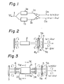
- FIG. 2 is a diagram explaining an operational principle of a laser light source device in accordance with the present invention.
- a laser 2 has an external resonator including reflection planes (reflection mirrors) 3 and 4, and a Faraday rotator 5 is provided in front of one of the reflection planes (reflection plane 4 in the figure), at the laser 2 side (i.e. within the external resonator).
- the Faraday rotator 5 has a different refractive index for the clockwise and counter-clockwise circular polarization, state, respectively, under a magnetic field.
- the clockwise and the counter-clockwise circular polarizations are in a time reversal relationship with each other. Namely, at that frequency, they are in a degenerate state. When a magnetic field is applied, the degenerate state is released, and one frequency becomes two frequencies.
- the two light components having different frequencies w+Aw and w-Aw are output through the reflection plane 4.
- the components passing through the reflection plane 4 have circular polarizations, the components can be separated and taken out by passing them through a quarter-wave plate and a polarization separating element (not shown). By the same process, the two components can be taken out from the reflection plane 3.
- the above-mentioned laser light source device is not limited to use with a gas laser, any arbitrary laser including those producing a circular polarization mode as an oscillatory light can also be used.
- TE-wave and TM-wave In a usual semiconductor laser, two linear polarizations crossing each other perpendicularly are called the TE-wave and the TM-wave, and are an eigenmode of the resonator.
- the polarization plane of the TE-wave In a semiconductor laser 21 as shown in Fig. 4, the polarization plane of the TE-wave is in parallel with, and the TM-wave is perpendicular to, an active layer 22 plane (hatched plane) which is the light emitting and waveguide domain.
- active layer 22 plane hatchched plane
- the TM-wave irradiated from the end plane 23 of the semiconductor laser 21 is given a circular polarization by the quarter-wave plate 6.
- This circular polarization is reflected by the reflection plane 3, and then is passed back through the quarter-wave plate 6, to again become a linear polarization.
- the wave has become a TE-wave.
- the light is irradiated from the end plane 24 and passes through the quarter-wave plate 7, and is then again given a circular polarization.
- This circular polarized wave is reflected by the reflection plane 4, is passed back through the quarter-wave plate 7, and is then returned as a TM-wave by the rotation of the polarization plane by n/2.
- the TE-wave irradiated from the end plane 23 of the semiconductor laser 21 is given a circular polarization in a reverse direction to that of the above case through the quarter-wave plate 6, and after the TE-wave is reflected by the reflection plane 3, the TE-wave is converted to a TM-wave through the quarter-wave plate 6. Further, the wave is irradiated from the end plane 24, is given a circular polarization in the reverse direction through the quarter-wave plate 7, is reflected by the reflection plane 4, and is then passed through the quarter-wave plate 7 and returned as a TE-wave.
- the oscillation light of the semiconductor laser 21 resonates in the degenerate state of the TE-wave and TM-wave between the reflection planes 3 and 4.
- the quarter-wave plates 6 and 7 are provided at both sides of the semiconductor laser 21, it is impossible to distinguish between the TE-mode and TM-mode.
- the semiconductor laser can be used as a light source in a manner equivalent to that of a gas laser.
- this semiconductor laser does not neet a reflection coating at the end planes 23 and 24, as do usual semiconductor lasers, it is preferable to apply the coating to prevent reflection.
- the Faraday rotator 5 for example, comprises a magnetic thin plate 5a made of yttrium-iron-garnet (YIG), which performs with the characteristic Faraday effect and is light transmissible, and a ring magnet 5b for magnetizing the magnetic thin plate 5a along a light transmitting direction ⁇ 1 or ⁇ 2 .
- the magnetic thin plate 5a is mounted in the ring of the ring magnet 5b.
- the construction of the light source device can be made smaller and control of the frequency difference made easier.
- the advantage is gained of obtaining two light components of constant intensity.
- a desired frequency difference ⁇ is fixed to a certain value, a permanent magnet can be used to supply the magnetic field. If an alternating magnetic field is applied, the frequency difference ⁇ can be modulated.
- Figure 5 shows an example of a practical constitution of a laser light source device according to the embodiment of the present invention shown in Fig. 3.
- a semiconductor laser is used as a light source.
- the semiconductor laser 21 is located on a heat sink 8, and, for example, spherical condenser lenses 9 and 10 are provided at both the light output ends of the semiconductor laser 21.
- Quarter-wave plates 61 and 71 are provided at both sides of the spherical lenses 9 and 10, respectively.
- One side of the quarter-wave plate 61 is coated with a reflection coating 31 having, for example, a reflectivity of 99 percent
- the Faraday rotator 5 is provided adjacent to one side of the quarter-wave plate 71.
- One side of the Faraday rotator 5 is coated with a reflection coating 41 having, for example, a reflectivity of 90 percent.
- the distance between the reflection coatings 31 and 41 is approximately 1 mm, the length between the end planes of the semiconductor laser 21 is approximately 0.3 mm, and the diameter of the spherical lenses 9 and 10 is approximately 0.2 mm.
- the quarter-wave plate can be made of a quartz plate having double refraction characteristics.
- Each element (2, 3, 4, 5, 6, 7) shown in Figs. 2 and 3, is in practice arranged on stems (not shown) made of non-magnetic metal, e.g., a stainless steel, using a holder for fixing, a cap (not shown) made of non-magnetic metal is attached to the stems to cover the elements, thus completing the casing of the elements.
- stems not shown
- non-magnetic metal e.g., a stainless steel
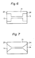
- Figures 6 and 7 show modifications of the present embodiment.
- the sectional area of the waveguide layer provided adjacent to the active layer of the semiconductor laser 21 is enlarged near the end planes 23 and 24 of the semiconductor laser 21 for receiving and sending the light.
- These areas are shown as reference numerals 13 and 14 in the plan views of Fig. 6 and Fig. 7, respectively.
- These modifications prevent reflection of the laser light at the end planes, and thus an external resonator type semiconductor laser light source device, wherein a complex mode rarely occurs and stable oscillation is performed, as obtained.
- the quarter-wave plates 6 and 7 used as the elements in the device of Fig. 3 can be replaced by 45 degree Faraday rotators made of yttrium-iron-garnet (YIG), for example, through which the polarization plane is rotated by 90 degrees for each light emission-and-return.
- YIG yttrium-iron-garnet
- the sectional form of the waveguide layer of the semiconductor laser may have anisotropic characteristcs. Namely, if the refractive index (of the waveguide layer) for the TE-wave is made to be different from that for the TM-wave, the interaction of the two waves becomes weaker, and thus a stable oscillation can be obtained.
- the Faraday rotator 5 having a polarization angle regarding the frequency 6.00 in the present embodiment can be made of a paramagnetic glass.
- the method of heterodyne measurement on light can be applied over a wide field. For example, if a magnetic field to be measured is applied to the Faraday rotator 5, the device operates as a light frequency modulator, and by utilizing the modulated data, a heterodyne type magnetic field measuring device is obtained.
Landscapes
- Physics & Mathematics (AREA)
- Electromagnetism (AREA)
- Engineering & Computer Science (AREA)
- Optics & Photonics (AREA)
- Condensed Matter Physics & Semiconductors (AREA)
- General Physics & Mathematics (AREA)
- Power Engineering (AREA)
- Plasma & Fusion (AREA)
- Semiconductor Lasers (AREA)
- Lasers (AREA)
Claims (8)
Applications Claiming Priority (4)
| Application Number | Priority Date | Filing Date | Title |
|---|---|---|---|
| JP17722783A JPH0249667B2 (ja) | 1983-09-26 | 1983-09-26 | Jikikogakusochi |
| JP177227/83 | 1983-09-26 | ||
| JP177233/83 | 1983-09-26 | ||
| JP17723383A JPS6068684A (ja) | 1983-09-26 | 1983-09-26 | レ−ザ光源装置 |
Publications (3)
| Publication Number | Publication Date |
|---|---|
| EP0138452A2 EP0138452A2 (de) | 1985-04-24 |
| EP0138452A3 EP0138452A3 (en) | 1987-04-29 |
| EP0138452B1 true EP0138452B1 (de) | 1990-12-19 |
Family
ID=26497847
Family Applications (1)
| Application Number | Title | Priority Date | Filing Date |
|---|---|---|---|
| EP84306546A Expired EP0138452B1 (de) | 1983-09-26 | 1984-09-26 | Laser-Lichtquelle |
Country Status (5)
| Country | Link |
|---|---|
| US (1) | US4637027A (de) |
| EP (1) | EP0138452B1 (de) |
| KR (1) | KR890003390B1 (de) |
| CA (1) | CA1251846A (de) |
| DE (1) | DE3483766D1 (de) |
Families Citing this family (28)
| Publication number | Priority date | Publication date | Assignee | Title |
|---|---|---|---|---|
| US4794605A (en) * | 1986-03-13 | 1988-12-27 | Trw Inc. | Method and apparatus for control of phase conjugation cells |
| EP0312296A3 (de) * | 1987-10-16 | 1990-04-11 | Board Of Regents, The University Of Texas System | Anordnung und Verfahren für "Quanten-nicht-zerstörende" Messungen unter Verwendung parametrischer Oszillation |
| US4944592A (en) * | 1987-10-16 | 1990-07-31 | The University Of Texas System | Device and method for quantum nondemolition measurements using parametric oscillation |
| CA1322599C (en) * | 1988-01-13 | 1993-09-28 | Nobuhiro Fukushima | Floating type magneto-optic disk reading head system having external semiconductor laser resonator operating at orthogonal two mode oscillations |
| GB8805016D0 (en) * | 1988-03-02 | 1988-03-30 | British Telecomm | Laser amplifier |
| US4941738A (en) * | 1988-07-29 | 1990-07-17 | American Telephone And Telegraph Company | Polarization independent optical amplifier apparatus |
| US5015070A (en) * | 1989-03-14 | 1991-05-14 | Mouse Systems Corporation | Reference grid for optical scanner |
| EP0396010A3 (de) * | 1989-05-05 | 1991-03-27 | Applied Materials, Inc. | Verfahren und Vorrichtung zur Überwachung der Wachstums- und Ätzgeschwindigkeit von Materialien |
| US4975918A (en) * | 1989-06-07 | 1990-12-04 | Maxwell Laboratories, Inc. | Tunable laser |
| US5022034A (en) * | 1989-06-27 | 1991-06-04 | May A D | Laser device, including control of polarization mode |
| US5007060A (en) * | 1989-08-01 | 1991-04-09 | Litton Systems, Inc. | Linear laser with two-swept frequencies of controlled splitting |
| FR2658367B1 (fr) * | 1990-02-13 | 1992-06-05 | Sagem | Laser fournissant deux ondes a des frequences differentes. |
| FR2682769B1 (fr) * | 1991-10-17 | 1995-08-11 | Sagem | Magnetometre laser. |
| US5247389A (en) * | 1992-06-15 | 1993-09-21 | Cygnus Laser Corporation | Nonlinear optical frequency converter |
| US5889609A (en) * | 1992-07-31 | 1999-03-30 | Fujitsu Limited | Optical attenuator |
| JP3167189B2 (ja) * | 1992-08-31 | 2001-05-21 | 浜松ホトニクス株式会社 | 電圧測定装置 |
| US5355381A (en) * | 1992-12-03 | 1994-10-11 | Amoco Corporation | Self-heterodyne optical fiber communications system |
| JP3667827B2 (ja) * | 1995-08-29 | 2005-07-06 | 富士通株式会社 | ファラデー回転子 |
| JP3739471B2 (ja) * | 1996-03-01 | 2006-01-25 | 富士通株式会社 | 光可変減衰器 |
| JP3773601B2 (ja) * | 1996-09-18 | 2006-05-10 | 富士通株式会社 | ファラデー回転子 |
| JPH10161076A (ja) * | 1996-11-29 | 1998-06-19 | Fujitsu Ltd | 磁気光学効果を利用した光デバイス |
| IL120754A0 (en) | 1997-05-01 | 1998-01-04 | Yeda Res & Dev | Optical resonators with discontinuous phase elements |
| US6496300B2 (en) | 1998-02-27 | 2002-12-17 | Fujitsu Limited | Optical amplifier |
| US6441955B1 (en) * | 1998-02-27 | 2002-08-27 | Fujitsu Limited | Light wavelength-multiplexing systems |
| US6212209B1 (en) * | 1998-03-16 | 2001-04-03 | Lucent Technologies, Inc. | Switchable laser using a faraday rotator |
| WO2001020732A1 (en) * | 1999-09-15 | 2001-03-22 | Yeda Research And Development Co. Ltd. | Optical resonators with orthogonally polarized modes |
| FR2915631B1 (fr) * | 2007-04-27 | 2009-07-10 | Thales Sa | Source laser compacte a faible largeur spectrale. |
| KR100815483B1 (ko) * | 2007-05-09 | 2008-03-20 | 한국전기연구원 | 비등방성 레이저 결정을 이용한 다이오드 펌핑된 레이저장치 |
Family Cites Families (6)
| Publication number | Priority date | Publication date | Assignee | Title |
|---|---|---|---|---|
| US3356438A (en) * | 1963-06-12 | 1967-12-05 | Sperry Rand Corp | Light modulator employing multiplereflective light path |
| GB1053086A (de) * | 1964-06-29 | |||
| US3639855A (en) * | 1969-12-19 | 1972-02-01 | Bell Telephone Labor Inc | Laser devices |
| US4222668A (en) * | 1978-02-23 | 1980-09-16 | Rockwell International Corporation | Ferrimagnetic Faraday elements for ring lasers |
| US4305046A (en) * | 1978-07-12 | 1981-12-08 | Agence Nationale De La Valorisation De La Recherche (Anvar) | Selective optical resonator |
| US4496518A (en) * | 1980-02-27 | 1985-01-29 | Marie G R P | TMO and TEO cavity resonator for projecting plasma confining TEO mode components |
-
1984
- 1984-09-17 CA CA000463409A patent/CA1251846A/en not_active Expired
- 1984-09-26 DE DE8484306546T patent/DE3483766D1/de not_active Expired - Lifetime
- 1984-09-26 EP EP84306546A patent/EP0138452B1/de not_active Expired
- 1984-09-26 US US06/654,628 patent/US4637027A/en not_active Expired - Fee Related
- 1984-09-26 KR KR8405900A patent/KR890003390B1/ko not_active Expired
Also Published As
| Publication number | Publication date |
|---|---|
| KR890003390B1 (en) | 1989-09-19 |
| KR850002611A (ko) | 1985-05-15 |
| EP0138452A3 (en) | 1987-04-29 |
| CA1251846A (en) | 1989-03-28 |
| US4637027A (en) | 1987-01-13 |
| EP0138452A2 (de) | 1985-04-24 |
| DE3483766D1 (de) | 1991-01-31 |
Similar Documents
| Publication | Publication Date | Title |
|---|---|---|
| EP0138452B1 (de) | Laser-Lichtquelle | |
| CA1304970C (en) | Polarization maintaining fiber interferometer and method for source stabilization | |
| US4890922A (en) | Thermally compensated reference interferometer and method | |
| US4274742A (en) | Passive ring laser rate of turn devices | |
| JPH05129700A (ja) | レーザシステム及び周波数変換方法 | |
| JPH0827193B2 (ja) | 改善されたバイアス安定度と再現性を有する光ファイバジャイロスコープ及びその製造方法 | |
| US5617435A (en) | Lasing system with wavelength-conversion waveguide | |
| US7190462B2 (en) | Fiber optic gyroscope having optical integrated circuit, depolarizer and fiber optic coil | |
| US7551342B2 (en) | Optical frequency comb generator and optical modulator | |
| JP2501302B2 (ja) | レ―ザ―装置および方法 | |
| US7764415B2 (en) | High retardation-amplitude photoelastic modulator | |
| EP0324684B1 (de) | Treibendes magneto-optisches Lesekopfsystem mit äusserem Halbleiterlaser mit Resonator, der in zwei orthogonalen Oszilliermoden funktioniert | |
| KR0174775B1 (ko) | 파장변환 도파로형 레이저 장치 | |
| US7009709B2 (en) | Active control of two orthogonal polarizations for heterodyne beam delivery | |
| JP2000162656A (ja) | 半導体デバイス | |
| GB2201256A (en) | Thermally compensated reference interferometer and method | |
| US3752586A (en) | Minimizing frequency locking in ring laser gyroscopes | |
| Boon-Engering et al. | Stabilization of an optical cavity containing a birefringent element | |
| JP2835874B2 (ja) | リングレーザジャイロ装置 | |
| JPH0136986B2 (de) | ||
| JPH11132718A (ja) | 干渉計測装置及び干渉計測装置用プローブ | |
| JP2835468B2 (ja) | リングレーザジャイロ装置 | |
| JP3301324B2 (ja) | 光電圧・電界センサ | |
| JPS62145213A (ja) | 光学的偏光状態変調器 | |
| US5737080A (en) | Solid state nonplanar laser gyroscope |
Legal Events
| Date | Code | Title | Description |
|---|---|---|---|
| PUAI | Public reference made under article 153(3) epc to a published international application that has entered the european phase |
Free format text: ORIGINAL CODE: 0009012 |
|
| AK | Designated contracting states |
Designated state(s): DE FR GB IT NL SE |
|
| PUAL | Search report despatched |
Free format text: ORIGINAL CODE: 0009013 |
|
| AK | Designated contracting states |
Kind code of ref document: A3 Designated state(s): DE FR GB IT NL SE |
|
| 17P | Request for examination filed |
Effective date: 19870730 |
|
| 17Q | First examination report despatched |
Effective date: 19890601 |
|
| ITF | It: translation for a ep patent filed | ||
| GRAA | (expected) grant |
Free format text: ORIGINAL CODE: 0009210 |
|
| AK | Designated contracting states |
Kind code of ref document: B1 Designated state(s): DE FR GB IT NL SE |
|
| REF | Corresponds to: |
Ref document number: 3483766 Country of ref document: DE Date of ref document: 19910131 |
|
| ET | Fr: translation filed | ||
| PLBE | No opposition filed within time limit |
Free format text: ORIGINAL CODE: 0009261 |
|
| STAA | Information on the status of an ep patent application or granted ep patent |
Free format text: STATUS: NO OPPOSITION FILED WITHIN TIME LIMIT |
|
| 26N | No opposition filed | ||
| PGFP | Annual fee paid to national office [announced via postgrant information from national office to epo] |
Ref country code: SE Payment date: 19930809 Year of fee payment: 10 |
|
| ITTA | It: last paid annual fee | ||
| PGFP | Annual fee paid to national office [announced via postgrant information from national office to epo] |
Ref country code: NL Payment date: 19930930 Year of fee payment: 10 |
|
| PG25 | Lapsed in a contracting state [announced via postgrant information from national office to epo] |
Ref country code: SE Effective date: 19940927 |
|
| EAL | Se: european patent in force in sweden |
Ref document number: 84306546.7 |
|
| PG25 | Lapsed in a contracting state [announced via postgrant information from national office to epo] |
Ref country code: NL Effective date: 19950401 |
|
| NLV4 | Nl: lapsed or anulled due to non-payment of the annual fee | ||
| EUG | Se: european patent has lapsed |
Ref document number: 84306546.7 |
|
| PGFP | Annual fee paid to national office [announced via postgrant information from national office to epo] |
Ref country code: FR Payment date: 20000912 Year of fee payment: 17 |
|
| PGFP | Annual fee paid to national office [announced via postgrant information from national office to epo] |
Ref country code: DE Payment date: 20000918 Year of fee payment: 17 |
|
| PGFP | Annual fee paid to national office [announced via postgrant information from national office to epo] |
Ref country code: GB Payment date: 20000920 Year of fee payment: 17 |
|
| PG25 | Lapsed in a contracting state [announced via postgrant information from national office to epo] |
Ref country code: GB Free format text: LAPSE BECAUSE OF NON-PAYMENT OF DUE FEES Effective date: 20010926 |
|
| REG | Reference to a national code |
Ref country code: GB Ref legal event code: IF02 |
|
| PG25 | Lapsed in a contracting state [announced via postgrant information from national office to epo] |
Ref country code: DE Free format text: LAPSE BECAUSE OF NON-PAYMENT OF DUE FEES Effective date: 20020501 |
|
| GBPC | Gb: european patent ceased through non-payment of renewal fee |
Effective date: 20010926 |
|
| PG25 | Lapsed in a contracting state [announced via postgrant information from national office to epo] |
Ref country code: FR Free format text: LAPSE BECAUSE OF NON-PAYMENT OF DUE FEES Effective date: 20020531 |
|
| REG | Reference to a national code |
Ref country code: FR Ref legal event code: ST |