EP0138494A2 - Dispositif d'allumage pour moteurs à combustion interne - Google Patents
Dispositif d'allumage pour moteurs à combustion interne Download PDFInfo
- Publication number
- EP0138494A2 EP0138494A2 EP84306677A EP84306677A EP0138494A2 EP 0138494 A2 EP0138494 A2 EP 0138494A2 EP 84306677 A EP84306677 A EP 84306677A EP 84306677 A EP84306677 A EP 84306677A EP 0138494 A2 EP0138494 A2 EP 0138494A2
- Authority
- EP
- European Patent Office
- Prior art keywords
- flip
- flop
- sensor
- ignition
- internal combustion
- Prior art date
- Legal status (The legal status is an assumption and is not a legal conclusion. Google has not performed a legal analysis and makes no representation as to the accuracy of the status listed.)
- Granted
Links
Images

Classifications
-
- F—MECHANICAL ENGINEERING; LIGHTING; HEATING; WEAPONS; BLASTING
- F02—COMBUSTION ENGINES; HOT-GAS OR COMBUSTION-PRODUCT ENGINE PLANTS
- F02P—IGNITION, OTHER THAN COMPRESSION IGNITION, FOR INTERNAL-COMBUSTION ENGINES; TESTING OF IGNITION TIMING IN COMPRESSION-IGNITION ENGINES
- F02P7/00—Arrangements of distributors, circuit-makers or -breakers, e.g. of distributor and circuit-breaker combinations or pick-up devices
- F02P7/02—Arrangements of distributors, circuit-makers or -breakers, e.g. of distributor and circuit-breaker combinations or pick-up devices of distributors
- F02P7/03—Arrangements of distributors, circuit-makers or -breakers, e.g. of distributor and circuit-breaker combinations or pick-up devices of distributors with electrical means
- F02P7/035—Arrangements of distributors, circuit-makers or -breakers, e.g. of distributor and circuit-breaker combinations or pick-up devices of distributors with electrical means without mechanical switching means
Definitions
- the present invention relates to an ignition apparatus for internal combustion engines, and particularly to an ignition apparatus for multi-cylinder internal combustion engines not using a high voltage distributor.
- a contactless ignition apparatus of this type has already been proposed in, for example, Japanese Patent Laid-Open No. 50263/1981.
- This apparatus has first and second sensors provided to correspond to the number of cylinders (for instance, two cylinders) of an internal combustion engine, and has first and second ignition coils that generate a secondary voltage to produce sparks for the internal combustion engine.
- the sensors are crank angle sensors that detect the igniting positions relying upon the turning of the rotor rotated by the engine.
- An igniting position control circuit and a conduction control circuit are operated by the signals from these sensors, the igniting positions and the conduction initiating positions are determined by an arithmetic circuit relying upon the outputs of these circuits, and the individual switching elements are controlled by the outputs of the arithmetic circuit thereby to control an electric current that flows into the ignition coils. Furthermore, provision is made of AND circuits in a number corresponding to the number of ignition coils, as well as n/2 flip-flop circuits when the number of AND circuits n is an even number, or flip-flop circuits when the number of AND circuits n is an odd number.
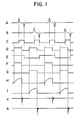
- Fig. 1 is a wave form diagram.
- Detection signals A of the first sensor and detection signals B of the second sensor are combined, and flip-flop circuits are operated to obtain rectangular output signals C.
- Signals obtained from the igniting position control circuit and the conduction control circuit, with the signals C as a reference, are modified by the arithmetic circuit to obtain signals D that include signals for the first and second cylinders.
- the signals are distributed. For example, when the signal E of the distributing flip-flop has a level of "1" (high level), the signal D, having a high level, is distributed as a signal F for the first cylinder through a logic gate.
- the signal D When the signal E has a level of "0" (low level), the signal D, having a low level, is distributed as a signal G for the second cylinder via a. logic gate.
- the thus distributed signals energize the first and second switching elements, whereby a primary current represented by a signal H flows into the first ignition coil, and a primary current represented by a signal inflows into the second ignition coil. Therefore, an ignition spark J generates in the first cylinder at the time of ignition for the first cylinder, and an ignition spark K also generates in the second cylinder.
- the signals D that have been combined for the first and second cylinders are distributed as signals F and signals G for each of the cylinders. Therefore, when the output conditions of the distributing flip-flop or the signals E do not properly correspond to the crank angle position of the engine, the ignition signal to be distributed to the first cylinder is erroneously distributed to the second cylinder, or conversely, the ignition signal to be distributed to the second cylinder is erroneously distributed to the first cylinder, resulting in erroneous ignition.
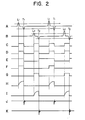
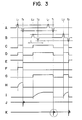
- Figs. 2 and 3 are diagrams of wave forms in the cases of cranking operation. The ignition will be described below more concretely with reference to these drawings.
- Crest values in the outputs of the first and second sensors of the type of tachometer generator change as shown, for example, by signals A and B, accompanying the change in the speed of revolution of the engine that results from the change in torque of the engine or the like. That is, if the instantaneous speed at a given moment is slow, the crest value produced by the sensor becomes low. During the time of cranking, there is generally no need of advancing the ignition timing, and the conduction control circuit does not need to be operated, either.
- the signal level at the position T2 detected by the second sensor does not reach the threshold voltage (lower dashed line of Fig. 3B) of the flip-flop during a time period t.
- the vicinity of position T2 corresponds to the latter half of the compression stroke of the engine where the engine turns most slowly. Therefore, the instantaneous speed of the engine is slow, and the crest value produced by the sensor is low.
- the flip-flop Upon receipt of the sensor output at the position T2, the flip-flop should have been inverted as represented by the signals C in Figs. 1 and 2. However, since the crest value is low as described above, the flip-flop is not inverted. Therefore, the level "1" of signal of Fig.
- the flip-flop which produces the signal E responsive to the sensor output at the position Tl receives a reset input.
- the signal E maintains a level of "0" until the flip-flop which produces the signal E at the next position T2 is set and inverted to a level of "1".
- Fig. 3D has the same wave forms as Fig. 3C. This is because there is no need of controlling the conduction ratio or the ignition timing during the period of cranking, and the wave forms of Fig. 3D become analogous to the wave forms of Fig. 3C.
- the signal F assumes the level “1” when the signal D has the level “1” and the signal E has the level “1".
- the signal G assumes the level “1” when the signal D assumes the level "1” and the signal E assumes the level "0”.
- F D ⁇ E
- G D ⁇ E. Therefore, the signal wave forms become as shown in Figs. 3F and 3G after the signal D has been distributed by the distributing flip-flop which produces the signal E.
- Interruption of the primary current from flowing into the first and second coils occurs each time that the signals F and G, respectively, go from a high to a low level. Therefore, the wave form of the primary current of the ignition coil for the first cylinder is as shown in Fig. 3H, and the ignition spark in the first cylinder is as shown in Fig. 3J.
- the wave form of the primary current of the ignition coil for the second cylinder is as shown in Fig. 3I
- the ignition spark in the second cylinder is as shown in Fig. 3K. It will be understood that although the position Tl corresponds to the ignition time for the first cylinder, the ignition spark is erroneously generated in the second cylinder as indicated by the circular dashed line.
- U.S. Patent No. 3,757,755 (issued to W.J. Carner on September 11, 1973) discloses an engine control apparatus according to which the ignition timing of each cylinder is calculated by a variable delay circuit using ignition timing signals for a plurality of cylinders, and the calculated results are distributed at a low voltage by a firing logic circuit for each of the cylinders.
- the object of the present invention is to eliminate the defects inherent in the prior art and to provide an ignition apparatus for internal combustion engines, wherein a flip-flop which is operated by a signal detected by the first sensor and a flip-flop which is operated by a signal detected by the second sensor, are provided separately from each other, and output signals of these flip-flop circuits are combined, so that the electric current will not be erroneously distributed even when the sensor outputs do not reach the operation levels of the flip-flop circuits.
- an ignition apparatus for an internal combustion engine comprising: at least two sensors driven by the engine, the first one providing first and second detection outputs respectively at first and second crank angle positions of the engine, and the second one providing third and fourth detection outputs respectively at third and fourth crank angle positions of the engine; a first bistable means operable by the first and second detection outputs of the first sensor; a second bistable means operable by the third and fourth detection outputs of the second sensor; a third bistable means operable by the first and third detection outputs or by the second and fourth detection outputs; means for combining the output signals of the first and second bistable means; and, means for distributing the combined signal into ignition signals corresponding to a predetermined number of cylinders.
- Fig. 4 is a circuit diagram of an ignition apparatus for internal combustion engines according to a preferred embodiment of the present invention, wherein provision is made of a first sensor 1 for detecting the crank angle position of the first cylinder and a second sensor 2 for detecting the crank angle position of the second cylinder.
- First and second diodes 3 and 4 are connected to the first sensor 1 to discriminate positive waves and negative waves in the output wave forms of the first sensor 1.
- Third and fourth diodes 5 and 6 are connected to the second sensor 2 to discriminate positive waves and negative waves in the output wave forms of the second sensor 2.
- a first flip-flop 7 has a set terminal S connected to the cathode of the first diode 3 and a reset terminal R connecred to the anode of the second diode 4.
- a second flip-flop 8 has a set terminal S connected to the cathode of the third diode 5, and a reset terminal R connected to the anode of the fourth diode 6.
- a first gate 9 consists of an OR circuit which combines an output signal c from the output terminal Q of the flip-flop 7 and an output signal d from the output terminal Q of the flip-flop 8.
- a third flip-flop 10 has a set terminal S connected to the anode of the fourth diode 6, and a reset terminal R connected to the anode of the second diode 4.
- a first transistor 13 interrupts the primary current i from flowing into a first ignition coil 15 responsive to the output signal g of the second gate 11.
- a second transistor 14 interrupts the primary current j from flowing into a second ignition coil 16 responsive to the output signal h of the third gate 12.
- a storage battery 17 which is a power source therefor.
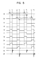
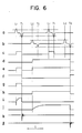
- Figs. 5 and 6 are diagrams of wave forms for explaining the operation of the embodiment of Fig. 4. Wave forms a to & are those of signals denoted by the same symbols in Fig. 4. Operation of the apparatus of Fig. 4 will be described below in conjunction with the wave forms of these diagrams.
- Fig. 5 explains the cranking operation. It is presumed that the crest values produced by the first and second sensors 1, 2 are greater than the operation levels of the flip-flop circuits 7, 8 and 10. A positive wave of the output signal a of the first sensor 1 generated at the position Ll passes through the first diode 3, and sets the flip-flop 7. Therefore, the flip-flop 7 produces a signal c of the level "1". The signal c continues until a negative wave of the first sensor 1 generated at the position Tl passes through the second diode 4 to reset the flip-flop 7. The signal c alternatingly assumes the level "0" and the level "1" in response to the signal a produced by the first sensor 1.
- a positive wave of the output signal b by the second sensor 2 generated at the position L2 for the second cylinder passes through the third diode 5 to set the flip-flop 8. Then, a negative wave generated at the subsequent position T2 passes through the fourth diode 6 to reset the flip-flop 8.
- the signal d produced by the flip-flop 8 alternatingly assumes the level "0" and "1" in response to the signal b produced by the second sensor 2.
- the above two output signals c and d are combined by the OR gate 9 as shown in Fig. 5e to cope with the two cylinders.
- the diodes 3 and 4 serve to discriminate the output signal a of the sensor 1 to set and reset the flip-flop 7 respectively while the diodes 5 and 6 serve to discriminate the output signal b of the sensor 2 to set and reset the flip-flop 8 respectively.
- the distributing flip-flop 10 is reset by the negative wave generated by the first snesor 1 at the position Tl, and is set by the negative wave generated by the second sensor 2 at the position T2. Therefore, the signal f produced by the flip-flop 10 alternatingly assumes the level "1" and the level "0" in response to the outputs of the first sensor 1 and the second sensor 2.
- the period in which the signal f assumes the level "1” is related to the first cylinder, and the period in which the signal f assumes the level "0" is related to the second cylinder.
- the signal e is provided as an output by the AND gate 11, and only during the period in which the signal f assumes the level "0", the signal e is provided as an output by the AND gate 12 (Figs. 5g and 5h).
- the primary current of the first ignition coil 15 starts to flow from the position Ll where the first transistor 13 is rendered conductive, and is interrupted at the position Tl where the first transistor 13 is rendered nonconductive and an ignition spark is produced at this moment (Figs. 5i and 5k).
- the primary current of the second ignition coil 16 starts to flow from the position L2 where the second transistor 14 is rendered conductive, and is interrupted at the position T2 where the second transistor 14 is rendered nonconductive and an ignition spark is produced at this moment (Figs. 5j and 5t) .
- the conduction ratio and the ignition timing are controlled by relying upon the output signal e of the OR gate 9, and the result is distributed as a signal for the first cylinder and a signal for the second cylinder using AND gates 11 and 12.
- the transistors are rendered conductive or nonconductive, and the primary current flows into the ignition coils for predetermined periods of time to build up sufficient amounts of energy. Then, a secondary high voltage is generated at igniting positions required for the engine.
- either the conduction ratio or the ignition period may be controlled.
- the output signal c of the flip-flop 7 is shown in Fig. 6c which is the same as Fig. 5c.
- the output signal d of the flip-flop 8 receives the positive wave of the second sensor 2 at the position L2 in the time section t, and rises from the level "0" to the level "1".
- the flip-flop 8 is not reset by the negative wave at the position T2, and the output signal d maintains the levle "1".
- the positive wave of the second sensor 2 at the position L2 of the next period is invalidated, and the signal d still maintains the level "1".
- the flip-flop 8 is then reset by the negative wave produced by the second sensor 2 at the position T2, and the output signal d returns to the level "0" as shown in Fig. 6.
- the OR gate 9 performs an OR operation on the signal c produced by the flip-flop 7 and the signal d produced by the flip-flop 8. Therefore, the signal produced by the OR gate 9 maintains the level "1" from the position L2 of time period t to the position T2 of the next period (Fig. 6e).
- the signal f produced by the distributing flip-flop 10 is inverted from the level "1" to the level "0" at the first position. Tl, and then maintains the level "0” until it is inverted again to the level "1" when the crank angle position is T2 for the second time (Fig. 6f).
- the signal g produced by the AND gate 11 maintains the level "1" from the position Ll to the first occurrence of position Tl (Fig. 6g), and the signal h produced by the AND gate 12 maintains the level "1" from the position L2 in the time period t to the position T2 of the next period (Fig. 6h).
- the primary current and the secondary voltage of the first ignition coil 15 are as shown in Figs. 6i and 6k, and the primary current and the secondary voltage of the second ignition coil 16 are as shown in Figs. 6j and 6Q.
- no ignition spark is generated at the second occurrence of position Tl for the first cylinder or the second cylinder, and there takes place no erroneous ignition resulting from erroneous distribution of current.
- the present invention is in no way limited to the above-mentioned embodiment but can be modified in a variety of ways.
- the above-mentioned embodiment has dealt with the case where the invention has been adapted to a two-cylinder engine having first and second cylinders
- the invention can also be adapted to engines having three or more cylinders by increasing the number of sensors and the numbers of diodes, flip-flop circuits and gates for sorting the positive and negative signals of the sensors, to obtain the same effects as those of the above-mentioned embodiment.
- NAND gates may be employed depending upon negative logics.
- the foregoing description further has described the ignition coils into which the primary current was permitted to flow so that the energy accumulated in the primary windings of the coils was turned into ignition sparks.
- the ignition coils need not necessarily be limited thereto.
- the signal f produced by the flip-flop 10 was associated with the first cylinder when it possessed the level "1". Conversely, the signal f may be associated with the first cylinder when it possesses the level "0".
- the flip-flop 10 was set and reset by the negative wave (position Tl) of the first sensor 1 and by the negative wave (position T2) of the second sensor 2.
- the gist of the invention is the same even when the flip-flop 10 is set and reset by using the positive wave (position Ll) of the first sensor 1 and by using the positive wave (position L2) of the second sensor 2.
Landscapes
- Engineering & Computer Science (AREA)
- Chemical & Material Sciences (AREA)
- Combustion & Propulsion (AREA)
- Mechanical Engineering (AREA)
- General Engineering & Computer Science (AREA)
- Ignition Installations For Internal Combustion Engines (AREA)
Applications Claiming Priority (2)
| Application Number | Priority Date | Filing Date | Title |
|---|---|---|---|
| JP181858/83 | 1983-09-28 | ||
| JP58181858A JPS6073059A (ja) | 1983-09-28 | 1983-09-28 | 内燃機関点火装置 |
Publications (4)
| Publication Number | Publication Date |
|---|---|
| EP0138494A2 true EP0138494A2 (fr) | 1985-04-24 |
| EP0138494A3 EP0138494A3 (en) | 1986-04-30 |
| EP0138494B1 EP0138494B1 (fr) | 1989-11-15 |
| EP0138494B2 EP0138494B2 (fr) | 1996-10-09 |
Family
ID=16108061
Family Applications (1)
| Application Number | Title | Priority Date | Filing Date |
|---|---|---|---|
| EP84306677A Expired - Lifetime EP0138494B2 (fr) | 1983-09-28 | 1984-09-28 | Dispositif d'allumage pour moteurs à combustion interne |
Country Status (4)
| Country | Link |
|---|---|
| US (1) | US4596227A (fr) |
| EP (1) | EP0138494B2 (fr) |
| JP (1) | JPS6073059A (fr) |
| DE (1) | DE3480488D1 (fr) |
Cited By (5)
| Publication number | Priority date | Publication date | Assignee | Title |
|---|---|---|---|---|
| DE3535789A1 (de) * | 1984-10-06 | 1986-04-10 | Hitachi, Ltd., Tokio/Tokyo | Zuendvorrichtung fuer einen verbrennungsmotor |
| WO1987002742A1 (fr) * | 1985-10-23 | 1987-05-07 | Robert Bosch Gmbh | Appareil transmetteur de signaux pour un distributeur d'allumage dans les moteurs a combustion interne |
| EP0244830A3 (en) * | 1986-05-08 | 1988-03-30 | Hitachi, Ltd. | Electronic ignition signal distributor for automobile engine |
| EP0443169A3 (en) * | 1990-02-22 | 1993-05-12 | Robert Bosch Gmbh | Ignition signal distributor in a high voltage static distribution system |
| US12398187B2 (en) | 2019-03-05 | 2025-08-26 | Nkarta, Inc. | CD19-directed chimeric antigen receptors and uses thereof in immunotherapy |
Families Citing this family (5)
| Publication number | Priority date | Publication date | Assignee | Title |
|---|---|---|---|---|
| GB8505874D0 (en) * | 1985-03-07 | 1985-04-11 | Ti Crypton Ltd | Engine analysers |
| DE3611262A1 (de) * | 1986-04-04 | 1987-10-08 | Bosch Gmbh Robert | Verfahren zur erkennung des arbeitstaktes eines zylinders einer brennkraftmaschine |
| KR910010035B1 (ko) * | 1987-05-14 | 1991-12-10 | 미쓰비시전기주식회사 | 점화시기 제어장치 |
| US4852536A (en) * | 1987-12-11 | 1989-08-01 | Outboard Marine Corporation | Trigger system for ignition system for internal combustion engines |
| DE102014216024A1 (de) * | 2013-11-14 | 2015-05-21 | Robert Bosch Gmbh | Verfahren zum Betreiben eines Zündsystems und entsprechendes Zündsystem |
Family Cites Families (15)
| Publication number | Priority date | Publication date | Assignee | Title |
|---|---|---|---|---|
| US4104997A (en) * | 1976-01-20 | 1978-08-08 | Motorola, Inc. | Multiple slope ignition spark timing circuit |
| JPS586065B2 (ja) * | 1976-06-21 | 1983-02-02 | 国産電機株式会社 | 多気筒内燃機関用点火装置 |
| DE2711894C2 (de) * | 1977-03-18 | 1983-12-15 | Robert Bosch Gmbh, 7000 Stuttgart | Vorrichtung zur Steuerung des Tastverhältnisses einer in ihrer Frequenz veränderbaren Signalfolge |
| GB2015080B (en) * | 1978-02-24 | 1982-12-15 | Hitachi Ltd | Contactless ignition system for use with internal combustion engines |
| US4208992A (en) * | 1978-03-20 | 1980-06-24 | Benito Polo | Electronic ignition system |
| FR2428152B1 (fr) * | 1978-06-07 | 1987-04-10 | Bosch Gmbh Robert | Dispositif pour la commande de processus fonction de parametres de marche et repetitifs pour moteurs a combustion interne |
| JPS5857631B2 (ja) * | 1978-06-23 | 1983-12-21 | 株式会社日立製作所 | 電子進角点火装置 |
| DE2961307D1 (en) * | 1978-08-09 | 1982-01-14 | Bosch Gmbh Robert | Ignition and fuel injection control system for internal combustion engines |
| JPS5632076A (en) * | 1979-08-22 | 1981-04-01 | Mitsubishi Electric Corp | Ignition timing correcting system for internal combustion engine |
| AT384862B (de) * | 1979-10-01 | 1988-01-25 | Jenbacher Werke Ag | Zuendeinrichtung fuer mehrzylindrige brennkraftmaschinen |
| US4378004A (en) * | 1981-02-23 | 1983-03-29 | Motorola Inc. | Engine control system with cylinder identification apparatus |
| US4347827A (en) * | 1981-06-01 | 1982-09-07 | Motorola, Inc. | Noise blanker circuit for use with electronic ignition systems or the like |
| JPS585469A (ja) * | 1981-06-30 | 1983-01-12 | Nec Home Electronics Ltd | エンジン点火装置 |
| US4385605A (en) * | 1981-10-13 | 1983-05-31 | Motorola Inc. | Electronic ignition input logic |
| US4462380A (en) * | 1982-12-20 | 1984-07-31 | Ford Motor Company | Enhanced spark energy distributorless ignition system |
-
1983
- 1983-09-28 JP JP58181858A patent/JPS6073059A/ja active Granted
-
1984
- 1984-09-26 US US06/654,501 patent/US4596227A/en not_active Expired - Lifetime
- 1984-09-28 DE DE8484306677T patent/DE3480488D1/de not_active Expired
- 1984-09-28 EP EP84306677A patent/EP0138494B2/fr not_active Expired - Lifetime
Cited By (5)
| Publication number | Priority date | Publication date | Assignee | Title |
|---|---|---|---|---|
| DE3535789A1 (de) * | 1984-10-06 | 1986-04-10 | Hitachi, Ltd., Tokio/Tokyo | Zuendvorrichtung fuer einen verbrennungsmotor |
| WO1987002742A1 (fr) * | 1985-10-23 | 1987-05-07 | Robert Bosch Gmbh | Appareil transmetteur de signaux pour un distributeur d'allumage dans les moteurs a combustion interne |
| EP0244830A3 (en) * | 1986-05-08 | 1988-03-30 | Hitachi, Ltd. | Electronic ignition signal distributor for automobile engine |
| EP0443169A3 (en) * | 1990-02-22 | 1993-05-12 | Robert Bosch Gmbh | Ignition signal distributor in a high voltage static distribution system |
| US12398187B2 (en) | 2019-03-05 | 2025-08-26 | Nkarta, Inc. | CD19-directed chimeric antigen receptors and uses thereof in immunotherapy |
Also Published As
| Publication number | Publication date |
|---|---|
| US4596227A (en) | 1986-06-24 |
| EP0138494B2 (fr) | 1996-10-09 |
| JPS6073059A (ja) | 1985-04-25 |
| DE3480488D1 (en) | 1989-12-21 |
| EP0138494B1 (fr) | 1989-11-15 |
| JPH0253628B2 (fr) | 1990-11-19 |
| EP0138494A3 (en) | 1986-04-30 |
Similar Documents
| Publication | Publication Date | Title |
|---|---|---|
| US4244336A (en) | Low speed limiter unit for internal combustion engine ignition systems | |
| US3908616A (en) | Ignition device for use in internal combustion engine | |
| US4747389A (en) | Crank angle detecting system for engines | |
| EP0138494B1 (fr) | Dispositif d'allumage pour moteurs à combustion interne | |
| US4520781A (en) | Ignition control system of internal combustion engine | |
| GB1582464A (en) | System for controlling the operability of one or more cylinders of a multicylinder internal combustion engine | |
| US4198936A (en) | System to control the on-off time of a pulse train of variable frequency, particularly the dwell time of ignition signals for an internal combustion engine | |
| GB2074758A (en) | Automatic control of fuel supply in ic engines | |
| US3898972A (en) | Ignition system for an internal combustion engine with automatic timing shift | |
| US4541390A (en) | Method and apparatus for determining an injection moment during a start process in an internal combustion engine | |
| SE424466B (sv) | Elektronisk tendsystem for flercylindriska forbrenningsmotorer | |
| KR950000220B1 (ko) | 엔진 제어 시스템 | |
| US4404940A (en) | Engine speed limiting circuit | |
| EP0203575B1 (fr) | Commande de l'avance à l'allumage lors d'une irrégularité du système détecteur de position de vilebrequin | |
| US4385617A (en) | Over-rotation preventing device for internal combustion engines | |
| US4658786A (en) | Loss of input signal detection and response system for use with distributorless ignition systems | |
| US4854292A (en) | Ignition system for internal combustion engine | |
| US4419974A (en) | Method of and apparatus for controlling the ignition timing of an internal combustion engine | |
| US4234850A (en) | Firing time control circuit | |
| US3768451A (en) | Ignition timing control system | |
| US4212280A (en) | Ignition system for internal combustion engines | |
| US4909229A (en) | Ignition system for an internal combustion engine | |
| EP0244830B1 (fr) | Distributeur électronique du signal d'allumage d'un moteur d'automobile | |
| JPS59110861A (ja) | 内燃機関点火装置 | |
| JPS58144664A (ja) | 内燃機関制御装置 |
Legal Events
| Date | Code | Title | Description |
|---|---|---|---|
| PUAI | Public reference made under article 153(3) epc to a published international application that has entered the european phase |
Free format text: ORIGINAL CODE: 0009012 |
|
| AK | Designated contracting states |
Designated state(s): DE FR GB |
|
| PUAL | Search report despatched |
Free format text: ORIGINAL CODE: 0009013 |
|
| AK | Designated contracting states |
Kind code of ref document: A3 Designated state(s): DE FR GB |
|
| 17P | Request for examination filed |
Effective date: 19860428 |
|
| 17Q | First examination report despatched |
Effective date: 19880414 |
|
| GRAA | (expected) grant |
Free format text: ORIGINAL CODE: 0009210 |
|
| AK | Designated contracting states |
Kind code of ref document: B1 Designated state(s): DE FR GB |
|
| REF | Corresponds to: |
Ref document number: 3480488 Country of ref document: DE Date of ref document: 19891221 |
|
| ET | Fr: translation filed | ||
| REG | Reference to a national code |
Ref country code: GB Ref legal event code: 727 |
|
| REG | Reference to a national code |
Ref country code: GB Ref legal event code: 727A |
|
| REG | Reference to a national code |
Ref country code: GB Ref legal event code: 727B |
|
| PLBI | Opposition filed |
Free format text: ORIGINAL CODE: 0009260 |
|
| REG | Reference to a national code |
Ref country code: GB Ref legal event code: SP |
|
| 26 | Opposition filed |
Opponent name: ROBERT BOSCH GMBH Effective date: 19900803 |
|
| PLAW | Interlocutory decision in opposition |
Free format text: ORIGINAL CODE: EPIDOS IDOP |
|
| PUAH | Patent maintained in amended form |
Free format text: ORIGINAL CODE: 0009272 |
|
| STAA | Information on the status of an ep patent application or granted ep patent |
Free format text: STATUS: PATENT MAINTAINED AS AMENDED |
|
| 27A | Patent maintained in amended form |
Effective date: 19961009 |
|
| AK | Designated contracting states |
Kind code of ref document: B2 Designated state(s): DE FR GB |
|
| APAC | Appeal dossier modified |
Free format text: ORIGINAL CODE: EPIDOS NOAPO |
|
| APAC | Appeal dossier modified |
Free format text: ORIGINAL CODE: EPIDOS NOAPO |
|
| ET3 | Fr: translation filed ** decision concerning opposition | ||
| REG | Reference to a national code |
Ref country code: GB Ref legal event code: IF02 |
|
| PGFP | Annual fee paid to national office [announced via postgrant information from national office to epo] |
Ref country code: FR Payment date: 20020910 Year of fee payment: 19 |
|
| PGFP | Annual fee paid to national office [announced via postgrant information from national office to epo] |
Ref country code: GB Payment date: 20020925 Year of fee payment: 19 |
|
| PGFP | Annual fee paid to national office [announced via postgrant information from national office to epo] |
Ref country code: DE Payment date: 20021002 Year of fee payment: 19 |
|
| PG25 | Lapsed in a contracting state [announced via postgrant information from national office to epo] |
Ref country code: GB Free format text: LAPSE BECAUSE OF NON-PAYMENT OF DUE FEES Effective date: 20030928 |
|
| PG25 | Lapsed in a contracting state [announced via postgrant information from national office to epo] |
Ref country code: DE Free format text: LAPSE BECAUSE OF NON-PAYMENT OF DUE FEES Effective date: 20040401 |
|
| GBPC | Gb: european patent ceased through non-payment of renewal fee |
Effective date: 20030928 |
|
| PG25 | Lapsed in a contracting state [announced via postgrant information from national office to epo] |
Ref country code: FR Free format text: LAPSE BECAUSE OF NON-PAYMENT OF DUE FEES Effective date: 20040528 |
|
| REG | Reference to a national code |
Ref country code: FR Ref legal event code: ST |
|
| APAH | Appeal reference modified |
Free format text: ORIGINAL CODE: EPIDOSCREFNO |