EP0138643B1 - Betätigungsvorrichtung für Eisenbahnselbstentladewagentüren und damit ausgestattete Entlader - Google Patents
Betätigungsvorrichtung für Eisenbahnselbstentladewagentüren und damit ausgestattete Entlader Download PDFInfo
- Publication number
- EP0138643B1 EP0138643B1 EP84401689A EP84401689A EP0138643B1 EP 0138643 B1 EP0138643 B1 EP 0138643B1 EP 84401689 A EP84401689 A EP 84401689A EP 84401689 A EP84401689 A EP 84401689A EP 0138643 B1 EP0138643 B1 EP 0138643B1
- Authority
- EP
- European Patent Office
- Prior art keywords
- trapdoor
- hand
- axis
- lever
- maintaining
- Prior art date
- Legal status (The legal status is an assumption and is not a legal conclusion. Google has not performed a legal analysis and makes no representation as to the accuracy of the status listed.)
- Expired
Links
- 230000010355 oscillation Effects 0.000 claims description 20
- 101100536354 Drosophila melanogaster tant gene Proteins 0.000 description 3
- 210000004027 cell Anatomy 0.000 description 2
- 230000007935 neutral effect Effects 0.000 description 2
- 241000897276 Termes Species 0.000 description 1
- 240000008042 Zea mays Species 0.000 description 1
- 239000006096 absorbing agent Substances 0.000 description 1
- 210000005069 ears Anatomy 0.000 description 1
- 230000000694 effects Effects 0.000 description 1
- 238000012423 maintenance Methods 0.000 description 1
- 239000012528 membrane Substances 0.000 description 1
- 230000000149 penetrating effect Effects 0.000 description 1
- 230000035939 shock Effects 0.000 description 1
Images


Classifications
-
- B—PERFORMING OPERATIONS; TRANSPORTING
- B61—RAILWAYS
- B61D—BODY DETAILS OR KINDS OF RAILWAY VEHICLES
- B61D7/00—Hopper cars
- B61D7/14—Adaptations of hopper elements to railways
- B61D7/16—Closure elements for discharge openings
- B61D7/24—Opening or closing means
- B61D7/30—Opening or closing means controlled by means external to cars
-
- B—PERFORMING OPERATIONS; TRANSPORTING
- B61—RAILWAYS
- B61D—BODY DETAILS OR KINDS OF RAILWAY VEHICLES
- B61D7/00—Hopper cars
- B61D7/14—Adaptations of hopper elements to railways
- B61D7/16—Closure elements for discharge openings
- B61D7/24—Opening or closing means
- B61D7/28—Opening or closing means hydraulic or pneumatic
Definitions
- the invention relates to a device for controlling the hopper hatches of wagons and to the hopper wagons and wagons which are provided with them.
- the device object of the invention, is intended to control the hatches only during these latter stages of controlling their closure.
- a result which the invention aims to obtain is a device for controlling hatch hopper doors of wagons, during the phases of controlling the closing of said hatches, which can be used for controlling a single hatch and therefore does not bind maintaining the doors to a synchronization of the movements of at least two doors.
- Another result which the invention aims to obtain is such a device in which the means for holding the doors does not risk releasing the doors in the event of an impact.
- the means for holding the hatch in the open position is chosen of a type such that its holding action can be annihilated by an oscillation d 'a part, and that on the one hand, to release the hatches, it makes this oscillation of the part necessary while, on the other hand, when it returns to the holding position, it guides the return of said part by waiting position for the subsequent release command.
- the wagon 1 comprises, at a certain distance above the rails 2, a chassis 3 carrying at least one hopper 4 (fig 1 and 2) whose base has at least one mouth 5 it even provided with at least one hatch 6 articulated around an axis 7 fixed in space relative to the chassis 3.
- This system 8 consists for example of an oleopneumatic accumulator 8, consisting of a hydraulic cylinder 9 whose end of the rod 10 of the piston is articulated around an axis 11 carried by a lever such as an ear 12 secured to the hatch 6 while the base of the cylinder 13 is articulated around an axis 14 carried by a lug 15 secured to the chassis 3.
- an oleopneumatic accumulator 8 consisting of a hydraulic cylinder 9 whose end of the rod 10 of the piston is articulated around an axis 11 carried by a lever such as an ear 12 secured to the hatch 6 while the base of the cylinder 13 is articulated around an axis 14 carried by a lug 15 secured to the chassis 3.
- a closed reservoir 16 At the base of the cylinder is connected a closed reservoir 16, which a flexible membrane 17 splits into two parts 18 and 19.
- One 18 of these two parts is connected to the cylinder 13 of cylinder 9, while the other 19 is filled with compressed air.
- the holding means 20 which comprises the device for controlling its closure
- the pressure of the compressed air drives the oil into the cylinder where it pushes back the piston whose rod 10 acts on the ear 12 to close the hatch 6.
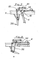
- the means 20 for holding the hatch 6 in the open position is chosen of a type such that its holding action can be annihilated by an oscillation of a part 22 and that, on the one hand , to release the hatch, it makes this oscillation of the part 22 necessary, while, on the other hand, when it returns to the holding position it guides the return of this part 22 to the waiting position for the subsequent command of release.
- This part 22 which is part of the means 21 for releasing the hatches consists, for example, of one end of one of the arms of a pendulum, 23 of which the end of another arm is grasped by the axis 24 of one end. of a rod 25 while by its part towards which the two arms converge this pendulum is articulated around an axis 26 fixed in space with respect to the chassis and, for example carried by a lug 27 welded on this chassis.
- the rod 25 forms with the arm a non-flat angle, preferably between thirty and one hundred and fifty degrees.
- the rod 25 is grasped by an axis 28 carried by a lever 29 articulated around an axis 30 fixed in space relative to the chassis and for example carried by a lug 31 welded to this chassis.
- the rod 25 and the lever 29 are in maximum elongation and, in the other direction, the compressive stress received from the balance being devoid of transverse component capable of causing the rod and the lever to oscillate, it will remain without effect on the articulated assembly formed by the lever 29 and the rod 25, located one after the other.
- a pendulum 32 is provided and, on the other hand, on the path of the wagon is fixed relative to the track a stop 33 which is situated at a height such that it will not be struck by the pendulum until the hatch is in the open position.
- the pendulum 32 is associated with the lever 29 so that, when the hatch 6 is kept in the open position, the said pendulum 32 is at least substantially vertical.
- the means 20 for holding the hatch can be of any known type such that its action can be annihilated by the oscillation of the part 22 and that, on the one hand, to release the hatch, it makes this oscillation of the part 22 necessary, while, on the other hand, when it returns to the holding position, it guides the return of this part 22 to the waiting position for the subsequent release command .
- This connecting rod must of course be incompressible to allow it to resist if necessary the action of the member 8 for controlling the closure.
- this connecting rod 34 may consist, in particular, of a tubular body 37 closed at one end by a base 38 and provided at the other end with two ears 39 forming a joint yoke.
- the base 38 is pierced in its axis with a cylindrical hole 40 to allow the sliding of a rod 41 completed, on the external side, by a yoke 42 and, on the other side, by a threaded part 43.
- a spring 44 is mounted inside the body around the rod carrying the yoke. This spring 44 is prestressed by means of a nut 45 and a ring 46 which produces a guide piece inside the tubular body 37.
- the device comprises means ensuring that the release of the hatch cannot be obtained only by oscillation of the part 22 in one direction, as is the case, for example, with the control of the balance 23 exposed above.
- the means 20 for holding the hatch 6 in the open position comprises, linked in rotation with the hatch 6, a ramp 49 (FIGS. 7 and 8) for example carried by the fields of the ear 12 on which acts the member 8 for controlling the opening of the hatch.
- This ramp 49 guides the end of the part 22, the oscillation of which controls the release of the hatch.
- a roller 50 is fixed to the end of said part 22.
- a spring 51 constantly keeps the roller 50 in abutment on the ramp 49 which in turn has a notch 52 in which the roller 50 falls when the hatch 6 is in the open position.
Landscapes
- Engineering & Computer Science (AREA)
- Transportation (AREA)
- Mechanical Engineering (AREA)
- Catching Or Destruction (AREA)
- Superstructure Of Vehicle (AREA)
- Filling Or Emptying Of Bunkers, Hoppers, And Tanks (AREA)
- Closing And Opening Devices For Wings, And Checks For Wings (AREA)
Claims (10)
Applications Claiming Priority (2)
| Application Number | Priority Date | Filing Date | Title |
|---|---|---|---|
| FR8314885 | 1983-09-14 | ||
| FR8314885A FR2551712B1 (fr) | 1983-09-14 | 1983-09-14 | Dispositif de commande des trappes de tremies de wagons et tremies et wagons pourvus d'un tel dispositif |
Publications (2)
| Publication Number | Publication Date |
|---|---|
| EP0138643A1 EP0138643A1 (de) | 1985-04-24 |
| EP0138643B1 true EP0138643B1 (de) | 1986-11-05 |
Family
ID=9292330
Family Applications (1)
| Application Number | Title | Priority Date | Filing Date |
|---|---|---|---|
| EP84401689A Expired EP0138643B1 (de) | 1983-09-14 | 1984-08-20 | Betätigungsvorrichtung für Eisenbahnselbstentladewagentüren und damit ausgestattete Entlader |
Country Status (6)
| Country | Link |
|---|---|
| EP (1) | EP0138643B1 (de) |
| DE (1) | DE3461160D1 (de) |
| ES (1) | ES535877A0 (de) |
| FR (1) | FR2551712B1 (de) |
| IL (1) | IL72922A (de) |
| PT (1) | PT79194A (de) |
Families Citing this family (3)
| Publication number | Priority date | Publication date | Assignee | Title |
|---|---|---|---|---|
| FR2610584B1 (fr) * | 1987-02-09 | 1989-05-19 | Leduc Rene Hydro Sa | Dispositif hydraulique de commande d'ouverture et de fermeture de trappes, de tremies, notamment pour wagons de chemin de fer |
| DE102008061294A1 (de) * | 2008-12-11 | 2010-06-17 | On Rail Gesellschaft für Eisenbahnausrüstung und Zubehör mbH | Klappenverschluss |
| WO2014120028A1 (en) | 2013-01-29 | 2014-08-07 | Ux2 Centrum Technologiczne Sp. Z.O.O. | The lock of the connection set for structural elements, the connection set with locks and the method of joining constructional elements with the use of the connection set |
Citations (1)
| Publication number | Priority date | Publication date | Assignee | Title |
|---|---|---|---|---|
| EP0133074A2 (de) * | 1983-07-29 | 1985-02-13 | Etablissements FAUVET - GIREL | Fülltrichterentladeklappen für Eisenbahnschüttgutwagen |
Family Cites Families (2)
| Publication number | Priority date | Publication date | Assignee | Title |
|---|---|---|---|---|
| GB1084105A (de) * | 1961-08-02 | |||
| FR2510505A1 (fr) * | 1981-07-31 | 1983-02-04 | Arbel Industrie | Dispositif de regulation des mouvements relatifs des trappes de tremies de wagons et wagons pourvus d'au moins un tel dispositif |
-
1983
- 1983-09-14 FR FR8314885A patent/FR2551712B1/fr not_active Expired
-
1984
- 1984-08-20 EP EP84401689A patent/EP0138643B1/de not_active Expired
- 1984-08-20 DE DE8484401689T patent/DE3461160D1/de not_active Expired
- 1984-09-12 IL IL72922A patent/IL72922A/xx unknown
- 1984-09-12 PT PT79194A patent/PT79194A/pt not_active IP Right Cessation
- 1984-09-13 ES ES535877A patent/ES535877A0/es active Granted
Patent Citations (1)
| Publication number | Priority date | Publication date | Assignee | Title |
|---|---|---|---|---|
| EP0133074A2 (de) * | 1983-07-29 | 1985-02-13 | Etablissements FAUVET - GIREL | Fülltrichterentladeklappen für Eisenbahnschüttgutwagen |
Also Published As
| Publication number | Publication date |
|---|---|
| IL72922A (en) | 1988-07-31 |
| ES8603155A1 (es) | 1985-12-01 |
| PT79194A (fr) | 1984-10-01 |
| ES535877A0 (es) | 1985-12-01 |
| FR2551712A1 (fr) | 1985-03-15 |
| DE3461160D1 (en) | 1986-12-11 |
| FR2551712B1 (fr) | 1986-01-31 |
| EP0138643A1 (de) | 1985-04-24 |
| IL72922A0 (en) | 1984-12-31 |
Similar Documents
| Publication | Publication Date | Title |
|---|---|---|
| EP1227948B1 (de) | Tankverschlussdeckel für kraftfahrzeug | |
| EP0019537A1 (de) | Wegziehbarer Greifer | |
| FR2866314A1 (fr) | Trappe de train d'atterrissage a cinematique controlee | |
| FR2697932A1 (fr) | Machine à affranchir modulaire comportant un dispositif d'assemblage de modules à centrage et verrouillage automatique. | |
| EP0138643B1 (de) | Betätigungsvorrichtung für Eisenbahnselbstentladewagentüren und damit ausgestattete Entlader | |
| WO2020020866A1 (fr) | Dispositif d'ouverture d'urgence d'une porte d'aéronef, à organe de retenue à crochet | |
| FR2769302A1 (fr) | Pince a leviers | |
| EP0029189B1 (de) | Zweiweg-Türschliesser | |
| WO2020094688A1 (fr) | Dispositif d'ouverture d'urgence d'une porte d'aéronef, à débrayage rotatif | |
| WO2020020860A1 (fr) | Dispositif d'ouverture d'urgence d'une porte d'aéronef, à organe de manoeuvre telescopique | |
| CA1147762A (fr) | Systeme modulaire pour ferme-porte | |
| EP3694802A1 (de) | Greifvorrichtung für schalen | |
| EP0151063B1 (de) | Vorrichtung zum automatischen oder manuellen Öffnen von Türen von Behälter von Sicherheitsausrüstung | |
| FR2568929A1 (fr) | Mecanisme de securite pour la manoeuvre des portes battantes a deux vantaux | |
| EP0414603A1 (de) | Betätigungseinrichtung für eine Steueranlage mit Bowdenzug | |
| EP0233090A1 (de) | Altglasbehälter | |
| FR2944547A1 (fr) | Dispositif de debrayage de tringle de serrure de porte pour vehicule, serrure de porte de vehicule et vehicule ainsi equipes | |
| FR2697566A1 (fr) | Serrure à pêne basculant. | |
| EP0592341A1 (de) | Verbesserung an Türgriffen mit einer plattenförmigen Handhabe | |
| FR2694316A1 (fr) | Chargeur-excavateur-élévateur. | |
| FR2657312A1 (fr) | Benne basculante munie d'un systeme de verrouillage de securite. | |
| FR2505037A1 (fr) | Mecanisme d'obturation d'un trou de coulee et four muni d'un tel mecanisme | |
| EP0297971B1 (de) | Vorrichtung zum Öffnen und Schliessen von Türen mit der Möglichkeit einer Zwischenöffnung, insbesondere für Drahtseilbahnkabinen | |
| BE1003725A3 (fr) | Agencement pour l'ouverture et la fermeture de la porte d'un vehicule mobile, tel qu'un vehicule a passagers. | |
| CA2320330A1 (fr) | Pince a souder electrique comportant un dispositif d'indexage et de desindexage mecanique |
Legal Events
| Date | Code | Title | Description |
|---|---|---|---|
| PUAI | Public reference made under article 153(3) epc to a published international application that has entered the european phase |
Free format text: ORIGINAL CODE: 0009012 |
|
| AK | Designated contracting states |
Designated state(s): BE DE GB IT LU NL |
|
| 17P | Request for examination filed |
Effective date: 19850321 |
|
| ITF | It: translation for a ep patent filed | ||
| GRAA | (expected) grant |
Free format text: ORIGINAL CODE: 0009210 |
|
| AK | Designated contracting states |
Kind code of ref document: B1 Designated state(s): BE DE GB IT LU NL |
|
| REF | Corresponds to: |
Ref document number: 3461160 Country of ref document: DE Date of ref document: 19861211 |
|
| PLBE | No opposition filed within time limit |
Free format text: ORIGINAL CODE: 0009261 |
|
| STAA | Information on the status of an ep patent application or granted ep patent |
Free format text: STATUS: NO OPPOSITION FILED WITHIN TIME LIMIT |
|
| 26N | No opposition filed | ||
| PGFP | Annual fee paid to national office [announced via postgrant information from national office to epo] |
Ref country code: LU Payment date: 19910724 Year of fee payment: 8 |
|
| PGFP | Annual fee paid to national office [announced via postgrant information from national office to epo] |
Ref country code: BE Payment date: 19910731 Year of fee payment: 8 |
|
| PGFP | Annual fee paid to national office [announced via postgrant information from national office to epo] |
Ref country code: GB Payment date: 19910805 Year of fee payment: 8 |
|
| PGFP | Annual fee paid to national office [announced via postgrant information from national office to epo] |
Ref country code: DE Payment date: 19910807 Year of fee payment: 8 |
|
| ITTA | It: last paid annual fee | ||
| PGFP | Annual fee paid to national office [announced via postgrant information from national office to epo] |
Ref country code: NL Payment date: 19910831 Year of fee payment: 8 |
|
| EPTA | Lu: last paid annual fee | ||
| PG25 | Lapsed in a contracting state [announced via postgrant information from national office to epo] |
Ref country code: LU Free format text: LAPSE BECAUSE OF NON-PAYMENT OF DUE FEES Effective date: 19920820 Ref country code: GB Effective date: 19920820 |
|
| PG25 | Lapsed in a contracting state [announced via postgrant information from national office to epo] |
Ref country code: BE Effective date: 19920831 |
|
| BERE | Be: lapsed |
Owner name: ARBEL INDUSTRIE S.A. Effective date: 19920831 |
|
| PG25 | Lapsed in a contracting state [announced via postgrant information from national office to epo] |
Ref country code: NL Effective date: 19930301 |
|
| NLV4 | Nl: lapsed or anulled due to non-payment of the annual fee | ||
| GBPC | Gb: european patent ceased through non-payment of renewal fee |
Effective date: 19920820 |
|
| PG25 | Lapsed in a contracting state [announced via postgrant information from national office to epo] |
Ref country code: DE Effective date: 19930501 |