EP0138694A2 - Fadenzufuhrvorrichtung für Rundstrickmaschine - Google Patents
Fadenzufuhrvorrichtung für Rundstrickmaschine Download PDFInfo
- Publication number
- EP0138694A2 EP0138694A2 EP84401988A EP84401988A EP0138694A2 EP 0138694 A2 EP0138694 A2 EP 0138694A2 EP 84401988 A EP84401988 A EP 84401988A EP 84401988 A EP84401988 A EP 84401988A EP 0138694 A2 EP0138694 A2 EP 0138694A2
- Authority
- EP
- European Patent Office
- Prior art keywords
- yarn
- rollers
- feed device
- pinion
- teeth
- Prior art date
- Legal status (The legal status is an assumption and is not a legal conclusion. Google has not performed a legal analysis and makes no representation as to the accuracy of the status listed.)
- Withdrawn
Links
- 238000009940 knitting Methods 0.000 title claims abstract description 11
- 230000003213 activating effect Effects 0.000 claims description 3
- 230000013011 mating Effects 0.000 claims description 2
- 230000001360 synchronised effect Effects 0.000 claims description 2
- 238000003801 milling Methods 0.000 claims 1
- 239000004744 fabric Substances 0.000 description 5
- 238000000926 separation method Methods 0.000 description 4
- 230000000903 blocking effect Effects 0.000 description 1
- 230000000694 effects Effects 0.000 description 1
- 238000000034 method Methods 0.000 description 1
- 230000000717 retained effect Effects 0.000 description 1
- 239000011435 rock Substances 0.000 description 1
Images



Classifications
-
- D—TEXTILES; PAPER
- D04—BRAIDING; LACE-MAKING; KNITTING; TRIMMINGS; NON-WOVEN FABRICS
- D04B—KNITTING
- D04B15/00—Details of, or auxiliary devices incorporated in, weft knitting machines, restricted to machines of this kind
- D04B15/38—Devices for supplying, feeding, or guiding threads to needles
- D04B15/48—Thread-feeding devices
Definitions
- the invention relates to a yarn feed device for a circular knitting machine equipped with stripers mounted in association with each set of machine cams and also in association with a needle removal zone of the needle cylinder, each of said devices being formed by a plurality of yarnguides, normally four, selectively operated by a pattern drum indexed through a ratchet wheel by a rotary moving control in synchronism with the needle cylinder, said control operating at the most once on each and every one of the ratchet wheels on each rotation of the machine.
- the stripers are mounted on the periphery of the machine at the rate of one striper per cam set, each striper generally receiving four yarns three of which are retained by the striper and the other is delivered selectively to the needles so that in operation the needles are fed with one of the four yarns.
- the changeover of the yarn fed to the needles by the striper is carried out at the most once on each rotation of the machine and always in one same needle cylinder zone, namely the so-called needle removal zone, having a width of 20 to 30 needles, at the start of which certain needles have been removed, whereas in the remaining portion the needle density is less than in the remainder of the cylinder.
- terry sinkers are used in the needle removal zone instead of jersey knit sinkers.
- the striper is actuated by a rotary moving control in synchronism with the needle cylinders, which control acts on a lever of the striper through pushers.
- the striper lever is provided with a pawl which indexes step by step a ratchet wheel attached to a pattern drum in which there are selectively inserted pins which cause levers associated with the moving yarnguides to rock.
- These yarnguides place the yarn in the path of the needles so that the latter pick it up and knit it.
- the yarn to be inserted is offered up so that the needles receive it and start knitting even while the previous yarn is still being knitted.
- two yarns are being knitted simultaneously, namely the incoming yarn and the outgoing one.
- the object of the invention is to provide a yarn feeder capable of overcoming the above drawbacks and of:
- the yarn feed device according to the invention being of the type described above, is characterised in that it comprises:
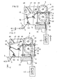
- the purpose of the striper 1 used in the invention is to supply the needles 2 of a circular knitting machine with the striping yarn 4 fed at the speed required by the needle consumption for knitting the desired fabric and partially to reduce the feed in the needle removal zone.
- the feed yarn is changed over without tense points in the incoming yarn or overfeeding of the outgoing yarn, the whole changeover cycle being carried out.
- the apparatus comprises a feed mechanism. 7, object of the invention which, as shown in Figures 2 and 3, comprises a set of toothed driving rollers 8 and a further set of driven rollers 9 mounted on respective parallel drive and driven shafts 10 and 11. Said rollers mesh with one another without making any contact, only for the purpose of pulling the yarn along ty the alternate friction effect as the yarn passes between the teeth.
- the rollers of each set are spaced apart and each pair of rollers 8, 9 of each set defines an operating space S, the face of the roller 8 (9) facing the operating space S being provided with a bevelled surface 8a (9a).
- a drive pulley 12 mounted on a shaft 13 carrying a bevel gear 14 meshing with a further bevel gear 15 mounted on the shaft 10, to which there is also attached a drive pinion 16.
- Pinion 16 drives a further driven pinion 17 attached to the shaft 11 of the other toothed roller 9, through two intermediate pinions 18 and 19 having respective shafts 21 and 22.
- a support head 27 supports the shafts 11 and 22 and pivots around shaft 22 and when the pivoting takes place, the teeth 23 of the rollers 8 and 9 come out of mesh. Conversely, in the meshed position, the teeth 23 of said rollers never make mutual contact, so that the yarn 4 is pulled along without suffering any damage and without losing the prior synchronism of rotation of said rollers 8 and 9.
- the shaft 10 is mounted in bearings 24 in the mechanism housing 25, while the shaft 11 is mounted in further bearings 26 in the head 27, which is urged against the housing 25 by a pring 28.
- toothed rollers 8, 9 on each shaft 10, 11, four are shown in Figure 3, since this is the usual number and they correspond to four striping yarns 4, although only one of them intervenes in each operation.
- the feed device receives the corresponding yarn 4 through yarnguides 30, each of which comprises a shaft 31 with two arms 32 each provided with an eyelet 33, one on the inlet side and the other on the outlet side, as seen in Figure 4.
- yarnguides 30 For each operating space S corresponding to the rollers 8, 9, there is a yarnguide 30.
- One of such yarnguides is in an operative position and the remainder are inoperative, as seen in Figure 3.
- Tiebars 34 act upon a terminal block 35 for a lever arm 36 of the yarnguide 30.
- Each pair of eyelets 33 defines a line which in an inoperative yarnguide 30 extends through the corresponding operating space S and in the operative yarnguide extends through a pair of rollers 8, 9.
- the head 27 pivots about the shaft 22 of the pinion 19 and is actuated from point 37 by a tiebar 38 connected to a slide 39 running on a cam track of a cam 4 0 disposed for moving the head 27 as shown in Figure 1.
- Figure 4 shows the yarnguide in the yarn feed position.-The yarn is caught by the teeth 23 of rollers 8 and 9 and delivered at constant speed to the needles 2.
- Figure 6 shows the yarnguide in the non-feeding position and in this position there is no engagement between the yarn 4 and the said rollers 8 and 9.
- Figure 5 relates to the first position mentioned which, in the needle removal zone on a striper change, continues in the feed position but delivering a lesser amount of yarn since, by pivoting of the support head 27, the engagement between the teeth 23 of the rollers 8 and 9 is less and therefore the amount of yarn fed is less, corresponding to the small amount used in the needle removal zone.
- Figures 7 to 10 show the running of the striper yarn 4 in the different stages of a cycle, with the intervention of a sensor 45 formed by a lever 46 connected to a traction spring 47 and movable between photoelectric sensors 48 and 49, the lever 46 being provided with a yarnguide eyelet 50 for the yarn 4 guided by a further two fixed leading and trailing eyelets 51 and 52.
- the striper yarn 4 starts the feed stage to the needles 2, whereby the sensor gives way under the tension of the yarn, breaking contact with the sensor 48 which immediately sends a command signal to the electromagnet 42 associated with the yarnguide 30 which pivots to place the yarn in the contact and feed area of the rollers 8 and 9.
- Figure 9 shows the yarn 4 being fed to the needles 2, whereby the eyelet 50 of the lever 46 is fully aligned with the eyelets 51 and 52, in which position the lever 46 intercepts the light ray of sensor 49.
- Figure 10 shows the moment of the striping changeover, whereby the yarn becomes slack, the lever 46 pivots and ceases to obstruct the sensor 49. Immediately the electromagnet operates and removes the yarnguide 30 from the feed zone. Under these conditions, the yarn 4 ceases to be"knit by the needles.
- Figure 7 shows the non-feeding yarnguides in the rest position, with the lever 46 blocking the light ray of sensor 48 and a new cycle is started.
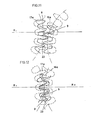
- FIG. 11 and 12 An alternative embodiment of the invention is shown in Figures 11 and 12 in which pinions 16a and 17a replace the pinions 16 and 17, to give a simplified mechanism.
- the pinions 16a and 17a are of corrected modulus as shown in the Figures.
- Figures 11 and 12 shows the former showing the maximum separation between the pinions 16a and 17a, while the latter shows the minimum separation between the rollers, such that in the former case there is a smaller meshing zone between the rollers 8 and 9 and in the latter a larger meshing zone for effective feeding of the yarns.
Landscapes
- Engineering & Computer Science (AREA)
- Textile Engineering (AREA)
- Knitting Machines (AREA)
Applications Claiming Priority (2)
| Application Number | Priority Date | Filing Date | Title |
|---|---|---|---|
| ES526625 | 1983-10-07 | ||
| ES526625A ES8407535A1 (es) | 1983-10-07 | 1983-10-07 | Perfeccionamientos en los alimentadores de hilo para telares circulares de genero de punto equipados con dispositivos listadores |
Publications (2)
| Publication Number | Publication Date |
|---|---|
| EP0138694A2 true EP0138694A2 (de) | 1985-04-24 |
| EP0138694A3 EP0138694A3 (de) | 1987-05-13 |
Family
ID=8486353
Family Applications (1)
| Application Number | Title | Priority Date | Filing Date |
|---|---|---|---|
| EP84401988A Withdrawn EP0138694A3 (de) | 1983-10-07 | 1984-10-04 | Fadenzufuhrvorrichtung für Rundstrickmaschine |
Country Status (4)
| Country | Link |
|---|---|
| US (1) | US4625528A (de) |
| EP (1) | EP0138694A3 (de) |
| JP (1) | JPS60104564A (de) |
| ES (1) | ES8407535A1 (de) |
Families Citing this family (6)
| Publication number | Priority date | Publication date | Assignee | Title |
|---|---|---|---|---|
| JPH052636Y2 (de) * | 1988-06-02 | 1993-01-22 | ||
| DE19511949B4 (de) * | 1995-03-31 | 2009-10-15 | Sipra Patententwicklungs- Und Beteiligungsgesellschaft Mbh | Strickmaschine und Fadenwechselvorrichtung |
| ES2210602T3 (es) * | 1998-01-23 | 2004-07-01 | Santoni S.P.A. | Dispositivo para alimentar hilos extensibles elasticamente a maquinas de genero de punto para fabricar medias o similares. |
| US6151925A (en) * | 1998-01-30 | 2000-11-28 | International Machinery Sales, Inc. | Methods and systems for positively feeding yarn to circular knitting machines |
| US6810694B2 (en) * | 2003-03-05 | 2004-11-02 | Sara Lee Corporation | Method of knitting an elastomeric yarn into a circularly knitted fabric |
| JP2007120150A (ja) * | 2005-10-28 | 2007-05-17 | Tostem Corp | 雨戸装置 |
Family Cites Families (10)
| Publication number | Priority date | Publication date | Assignee | Title |
|---|---|---|---|---|
| US1726568A (en) * | 1927-05-27 | 1929-09-03 | Celanese Corp | Knitting machine |
| DE610129C (de) * | 1934-01-17 | 1935-03-04 | C A Roscher Soehne | Fadenzubringevorrichtung fuer Strick- und Wirkmaschinen |
| US2247244A (en) * | 1939-06-28 | 1941-06-24 | Lawson Products Inc | Strand feed-controlling mechanism for textile or other machines |
| US2293838A (en) * | 1941-04-03 | 1942-08-25 | Lawson Products Inc | Selective machine stopping means positively operated upon yarn cessation in yarn-changing furnishing mechanism |
| US2432685A (en) * | 1946-06-29 | 1947-12-16 | Malden Spinning & Dyeing Compa | Yarn feeding mechanism |
| FR1490470A (fr) * | 1965-05-18 | 1967-08-04 | Ct Tech Ind I Textile De Franc | Procédé d'alimentation des métiers de bonneterie en fils à fort allongement, à un débit et à une tension constants et fournisseur de fils permettant la réalisation dudit procédé |
| US3418831A (en) * | 1967-10-27 | 1968-12-31 | Ertle Williamson | Feed control for automatic striper |
| DE1946559A1 (de) * | 1969-09-13 | 1971-03-18 | Krenzler Fa Emil | Mehrfaedige,ein- oder mehrsystemige Strickmaschine |
| US3739603A (en) * | 1971-04-26 | 1973-06-19 | M Philip | Apparatus and method for feeding strands, and elements thereof |
| IL42395A0 (en) * | 1972-06-05 | 1973-07-30 | Solis Srl | Feeder and equalizer device for yarns designed for multi-feed hosiery machines |
-
1983
- 1983-10-07 ES ES526625A patent/ES8407535A1/es not_active Expired
-
1984
- 1984-10-04 EP EP84401988A patent/EP0138694A3/de not_active Withdrawn
- 1984-10-08 JP JP59209951A patent/JPS60104564A/ja active Pending
-
1986
- 1986-01-21 US US06/820,592 patent/US4625528A/en not_active Expired - Fee Related
Also Published As
| Publication number | Publication date |
|---|---|
| JPS60104564A (ja) | 1985-06-08 |
| US4625528A (en) | 1986-12-02 |
| ES526625A0 (es) | 1984-10-01 |
| ES8407535A1 (es) | 1984-10-01 |
| EP0138694A3 (de) | 1987-05-13 |
Similar Documents
| Publication | Publication Date | Title |
|---|---|---|
| US4193358A (en) | Tufting machines | |
| US3756043A (en) | Flat warp knitting machines | |
| US4625528A (en) | Yarn feed device for a circular knitting machine | |
| EP0147139A2 (de) | Jacquard-Rundstrickmaschine | |
| EP0683257B1 (de) | Rundstrickmaschine mit Platinen zum Festhalten des Gestricks | |
| US4442684A (en) | Control of weft thread insertion | |
| US4069690A (en) | Knitting apparatus | |
| EP0257036B1 (de) | Fadenliefervorrichtung | |
| US3648459A (en) | Warp knitting machine, particularly raschel machine | |
| JPS5812380B2 (ja) | 経編機及びその使用法 | |
| US3609997A (en) | Warp knitting machine | |
| US3701267A (en) | Warp knitting machine | |
| US2309026A (en) | Thread tensioning mechanism for textile fabricating machines | |
| US3834189A (en) | Warp knitting machine | |
| US1927683A (en) | Yarn-feeding device fob circular | |
| US4127012A (en) | Stitch selector control means | |
| US3350901A (en) | Guide bar lapping mechanism for warp knitting machines | |
| US4570460A (en) | Warp feeding device for circular knitting machine | |
| US4852370A (en) | Warp-knitting machine, particularly stitch knitting machine | |
| US1236770A (en) | Striping attachment for knitting-machines. | |
| US1008752A (en) | Striping and embroidering mechanism for knitting-machines. | |
| CA1291881C (en) | Device for manufacturing knitted bags with a circular machine for tubularknitwear moving with continuous and unidirectional motion, and machine equipped with such a device | |
| US2409306A (en) | Knitting machine | |
| US4759201A (en) | Winding thread device | |
| JP2527850B2 (ja) | シンカ―制御装置 |
Legal Events
| Date | Code | Title | Description |
|---|---|---|---|
| PUAI | Public reference made under article 153(3) epc to a published international application that has entered the european phase |
Free format text: ORIGINAL CODE: 0009012 |
|
| AK | Designated contracting states |
Designated state(s): DE FR GB IT |
|
| PUAL | Search report despatched |
Free format text: ORIGINAL CODE: 0009013 |
|
| AK | Designated contracting states |
Kind code of ref document: A3 Designated state(s): DE FR GB IT |
|
| STAA | Information on the status of an ep patent application or granted ep patent |
Free format text: STATUS: THE APPLICATION IS DEEMED TO BE WITHDRAWN |
|
| 18D | Application deemed to be withdrawn |
Effective date: 19871116 |
|
| RIN1 | Information on inventor provided before grant (corrected) |
Inventor name: DALMAU GUEELL, JOSE MARIA |