EP0139146A2 - Cassette pour disque d'enregistrement - Google Patents
Cassette pour disque d'enregistrement Download PDFInfo
- Publication number
- EP0139146A2 EP0139146A2 EP84109820A EP84109820A EP0139146A2 EP 0139146 A2 EP0139146 A2 EP 0139146A2 EP 84109820 A EP84109820 A EP 84109820A EP 84109820 A EP84109820 A EP 84109820A EP 0139146 A2 EP0139146 A2 EP 0139146A2
- Authority
- EP
- European Patent Office
- Prior art keywords
- case
- half case
- insertion hole
- recording disc
- bosses
- Prior art date
- Legal status (The legal status is an assumption and is not a legal conclusion. Google has not performed a legal analysis and makes no representation as to the accuracy of the status listed.)
- Granted
Links
Images



Classifications
-
- G—PHYSICS
- G11—INFORMATION STORAGE
- G11B—INFORMATION STORAGE BASED ON RELATIVE MOVEMENT BETWEEN RECORD CARRIER AND TRANSDUCER
- G11B23/00—Record carriers not specific to the method of recording or reproducing; Accessories, e.g. containers, specially adapted for co-operation with the recording or reproducing apparatus ; Intermediate mediums; Apparatus or processes specially adapted for their manufacture
- G11B23/02—Containers; Storing means both adapted to cooperate with the recording or reproducing means
- G11B23/03—Containers for flat record carriers
-
- G—PHYSICS
- G11—INFORMATION STORAGE
- G11B—INFORMATION STORAGE BASED ON RELATIVE MOVEMENT BETWEEN RECORD CARRIER AND TRANSDUCER
- G11B23/00—Record carriers not specific to the method of recording or reproducing; Accessories, e.g. containers, specially adapted for co-operation with the recording or reproducing apparatus ; Intermediate mediums; Apparatus or processes specially adapted for their manufacture
- G11B23/02—Containers; Storing means both adapted to cooperate with the recording or reproducing means
- G11B23/03—Containers for flat record carriers
- G11B23/033—Containers for flat record carriers for flexible discs
- G11B23/0332—Containers for flat record carriers for flexible discs for single discs, e.g. envelopes
Definitions
- the present invention relates to a recording disc cartridge having a magnetic recording disc or an optical recording disc enclosed in a disc case.
- Fig. 1 shows a recording disc cartridge having a disc case 1 and a recording disc 2 rotatably enclosed in the disc case 1.
- the disc case 1 is formed by a top half case la and a bottom half case lb both of which are combined together by a tapping screws or by an ultrasonic welding method.
- the top section la and the bottom section lb are not shaped completely same although they have almost similar shape partly because they are fitted together by engagement of projected walls formed on the peripheral part of one of the half cases with recesses defined on another half case corresponding to the projected walls and partly because the detection notches on the both half cases are defined out of the center line of the disc case.
- the essential object of the present invention is to provide a recording disc cartridge formed by a pair of a top section and a bottom section having a completely same shape so as to improve the productivity of the recording disc cartridge with the production cost reduced.
- a recording disc cartridge which comprises a disc case composed of a top half case and a bottom half case each half case being provided with peripheral walls formed on the disc case, a drive shaft insertion hole defined on the central portion of the half case and a head insertion hole defined on a portion apart from said drive shaft insertion hole in the frontward direction on the central portion of the disc case relative to the left and right direction .
- each of the said top half case and the bottom half case is provided with at least one pair of connecting bosses in such a manner that the connection bosses of one of the half cases are engageable with the corresponding connecting bosses of the other half case and that the connecting bosses are disposed in a symmetrical position relative to a phantom line passing the center of the head insertion hole and the center of the drive shaft insertion hole.
- the recording disc cartridge of the first embodiment of the present invention comprises the disc case 1 having a generally flat rectangular shape in plan view and the magnetic or optical recording disc 2 rotatably accommodated in the disc case 1.
- the disc case 1 is composed of the top half case la and the bottom half case lb each made of plastic resin, and formed generally in the flat plate with the four peripheral sides surrounded by low vertical peripheral walls 11.
- the top half case la and the bottom half case lb are assembled together with the bottom face of the peripheral walls 11 of the top half case la abutted to the corresponding top face of the peripheral walls 11 of the bottom case lb so as to provide a flat space for accommodation of the recording disc 2.
- both top and bottom half cases la and lb there are defined a pair of drive shaft insertion holes 3 through the both half cases with a pair of elongated head insertion holes 4 defined extending from the drive shaft insertion holes toward the front portion of the disc case 1.
- the recording disc 2 is formed by a magnetic recording sheet 5 of an annular shape and a hub 6 fixed on the central part of the recording sheet 5 with the top end face and the bottom end face of the hub faced to the drive shaft insertion holes 3.
- the recording disc 2 can be rotated by rotation of the disc drive members of the disc drive apparatus clamping the hub 6, so that the recording disc 2 slidingly rotates on the cleaning sheets 8 of non woven sheet laid on the inner surfaces of the top and bottom half cases la and lb.
- the present invention is characterized in that the top half case la and the bottom half case lb have a completely same shape.
- the rear portions of the top half case la and the bottom half case lb are provided with a pair of projected portions 10 expanded symmetrically in the right and left directions and the rear portion of the half case is wider than the front portion of the half case for preventing an erroneous mounting of the disc case 1 on the disc drive apparatus with the front side of the disc case wrongly taken as the rear side thereof.
- the peripheral walls 11 are formed on the respective peripheral edges of the top half case la and the bottom half case lb and four arcuated partition walls 13 are formed conforming to the outermost circle of the recording disc 2 at the respective corner portions of the disc case 1 so as to provide a disc receiving chamber 12.
- the lower faces of the respective walls 11 and 13 of the top half case la are contacted with the upper faces of the walls 11 and 13 of the bottom half case lb upon assembling of the both halves.
- each of the drive insertion holes 3 is piercingly defined in an annular shape at the central portion of the disc receiving chamber 12 with the head insertion hole 4 communicating with the drive shaft insertion hole 3 so as to extend toward the front portion of the disc case 1 in connection with the center of the lateral direction or left and right direction of the disc case 1.
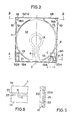
- the peripheral edges 41 and 42 defining the head insertion hole 4 run parallelly with an equal distance to the phantom line P (see Fig.2) running in the longitudinal direction of the disc case 1 passing the center of the drive shaft insertion hole 3 and perpendicularly intersecting with the front edge of the disc case 1.
- the center of the drive shaft insertion hole 3 must be coincided with the center relative to the lateral direction of the disc case but it is not essential to define the center of the drive shaft insertion hole 3 at the center relative to the longitudinal direction of the disc case 1.
- a plurality of connecting bosses 15A, 15B, 16A and 16B are projectingly formed on the inner surface of each of the halves la and lb for connecting the top half case la and the bottom half case lb.
- the bosses 15A and 15B situated at the rear portion of the disc case make one pair and the bosses 16A and 16B make another pair.
- the left connecting boss 15A is a cylindrical column having a funnel shaped cpening 17 at the top end portion and is taller than the top butting face of the peripheral wall 11 of the top half case la (or 1B).
- the right connecting boss 15B has a hole 19 engageable with the boss 15A of the other half case with a height equal to the top level of the peripheral wall 11.
- the connecting bosses 15A and 15B are disposed at the symmetrical position relative to the phantom line P.
- the connecting bosses 16A and 16B are disposed at the symmetrical position relative to the phantom line P similar to the connecting bosses 15A and 15B, and the connecting boss 16A has the same configuration of the connecting boss 15B having the hole 19 and the connecting boss 16B is formed in the same manner as the shape of the connecting boss 15A having the funnel shaped opening 17. It is noted that the connecting bosses 15A and 15B on the front side of the both top halves la and lb are closely fitted, to the contrary, the connecting bosses 16A and 16B are loosely fitted.
- a partition wall 50 is provided at the corner where the connecting boss 15B exists so as to provide a small chamber 20, wherein an erase preventing chip 21 is formed by cutting the part of the half section in a U character shape.
- a shallow slot 22 is formed at the root of the chip 21 so as to facilitate to manually separate the chip 21 from the half case for preventing erase of the record.
- a shallow rectangular recess 25 is formed on the top face of the top half case la for fitting a label and in Fig. 2, reference numeral 26 denotes a gate for injection of plastic resin when injection molding.
- top half case la and the bottom half case lb are assembled together in such a manner as described below.
- the cleaning liners 8 are laid in the inner surfaces of the disc receiving chamber 12 with the opening of the cleaning sheet 8 coincided with the head insertion hole 4 and then secured by a thermal welding or a supersonic welding or adhering material. Subsequently the recording disc 2 is put on the disc receiving chamber 12 of the bottom half case lb with the hub 6 opposed to the drive shaft insertion hole 3. Then the top half case la to which the cleaning sheet was already secured is assembled to the bottom half case lb fitting the connecting bosses 15A and 15B situated at the front portion of the both halves la and lb, thereby positioning between the both halves la and lb is made, and in turn the connecting bosses 16A and 16B situated at the rear portion of the both halves la and lb are fitted.
- the connecting bosses 16A and 16B on the rear portion of the both halves la and lb are fitted looser than the fitting between the connecting bosses 15A and 15B on the both halves la and lb, in addition to the manner of engagement between the connecting bosses 16A and 16B on the rear portion of the both halves la and lb is inverse of the manner of engagement between the connecting bosses 15A and 15B on the front portion, the top half case la and the bottom half case lb can be smoothly assembled with a high accuracy preventing an erroneous assembling in such a manner that the two half cases are assembled in a reversed manner.
- the both halves can be securedly connected by the ultrasonic welding method. Since there are formed the funnel shaped openings 17 on the end portion of the connecting bosses 15A and 16B, the welding can be well performed. In welding, if there is a partly butting portion on the ends of the walls 11 and 13, there may occur flash.
- peripheral walls 11 are formed with the inner part thereof high and the outer part thereof to be downwardly stepped as shown by 27 in Fig. 6 so as to prevent the occurrence of the flash whereby the both halves la and lb can be secured between the butting faces of the peripheral walls 11.
- Said stepped portions 27 may be formed on the left and right peripheral walls, the front peripheral wall and the part of the rear peripheral wall adjacent to the connecting bosses 16A and 16B as shown in Fig. 2. However, such stepped portion 27 may be formed only the four corners of the both halves adjacent to the connecting bosses.
- the top half case la should be assembled to the bottom half case lb from right above.
- the distance between the two connecting bosses 15A and 15B in the front portion is different from the distance between the connecting bosses 16A and 16B for preventing erroneous assembling of the both halves la and lb, however, the value of the distance is not limited to the distance shown in this embodiment.
- the relation of the engagement of the connecting bosses 16A and 16B on the rear portion of the half cases la and lb may be the same as the relation of the engagement between the connecting bosses 15A and 15B as shown in Fig. 8so far as the engagement of the connecting bosses is performed by the engagement between the projection and the recess.
- the connecting bosses 15A, 15B, 16A and 16B may be provided only for connecting the top half case la and the bottom half case lb by only abutting the ends of the respective connecting bcsses without the fitting engagement.
- the connecting bosses 15A through 16B on one of the half cases are provided with through holes and the connecting bosses on the other half case (for example Ib ) are formed screw holes so that the both half cases la and lb can be connected by tapping screws tapped into the screw holes through the through holes.
- the present invention can be applied to optical recording disc cartridges and/or recording disc cartridges having shutter means for open and close the head insertion hole 4.
- the recording disc cartridge according to the present invention can be manufactured by the same mold for the top half case and the bottom half case since they have symmetrical configuration, thereby resulting in reducing the manufacturing cost.
- the manufacturing process schedule can be simplified by commonly using only one kind of the half case for the top half case and the bottom half case.
Landscapes
- Packaging For Recording Disks (AREA)
Priority Applications (1)
| Application Number | Priority Date | Filing Date | Title |
|---|---|---|---|
| EP89101031A EP0320492B1 (fr) | 1983-08-24 | 1984-08-17 | Cassette à disque d'enregistrement |
Applications Claiming Priority (2)
| Application Number | Priority Date | Filing Date | Title |
|---|---|---|---|
| JP58155233A JPH0640428B2 (ja) | 1983-08-24 | 1983-08-24 | ディスクカートリッジ |
| JP155233/83 | 1983-08-24 |
Related Child Applications (1)
| Application Number | Title | Priority Date | Filing Date |
|---|---|---|---|
| EP89101031.6 Division-Into | 1984-08-17 |
Publications (3)
| Publication Number | Publication Date |
|---|---|
| EP0139146A2 true EP0139146A2 (fr) | 1985-05-02 |
| EP0139146A3 EP0139146A3 (en) | 1986-04-30 |
| EP0139146B1 EP0139146B1 (fr) | 1990-06-27 |
Family
ID=15601442
Family Applications (1)
| Application Number | Title | Priority Date | Filing Date |
|---|---|---|---|
| EP84109820A Expired EP0139146B1 (fr) | 1983-08-24 | 1984-08-17 | Cassette pour disque d'enregistrement |
Country Status (5)
| Country | Link |
|---|---|
| US (1) | US4573572A (fr) |
| EP (1) | EP0139146B1 (fr) |
| JP (1) | JPH0640428B2 (fr) |
| KR (1) | KR910009435B1 (fr) |
| DE (2) | DE3482610D1 (fr) |
Cited By (3)
| Publication number | Priority date | Publication date | Assignee | Title |
|---|---|---|---|---|
| EP0391588A3 (en) * | 1989-04-06 | 1990-11-07 | Sony Corporation | Disc cartridge |
| EP0592886A3 (fr) * | 1992-10-13 | 1995-02-15 | Fuji Photo Film Co Ltd | Cassette à disque magnétique. |
| US5768253A (en) * | 1992-05-15 | 1998-06-16 | Cd Plant Tecval S.A. | Disc cartridge for accommodating recording discs |
Families Citing this family (12)
| Publication number | Priority date | Publication date | Assignee | Title |
|---|---|---|---|---|
| JPH0325331Y2 (fr) * | 1984-10-03 | 1991-05-31 | ||
| DE3521383A1 (de) * | 1985-06-14 | 1986-12-18 | Basf Ag, 6700 Ludwigshafen | Verfahren und vorrichtung zur herstellung von huellen fuer flexible magnetspeicherscheiben |
| JPS6214368A (ja) * | 1985-07-11 | 1987-01-22 | Victor Co Of Japan Ltd | デイスク駆動装置 |
| US4644521A (en) * | 1985-08-14 | 1987-02-17 | Laser Magnetic Storage International Company | Optical memory cartridge and drive apparatus |
| JPH0739108Y2 (ja) * | 1986-01-20 | 1995-09-06 | ソニー株式会社 | ディスクカートリッジ |
| JPH01106603U (fr) * | 1988-01-07 | 1989-07-18 | ||
| JP2743525B2 (ja) * | 1989-10-24 | 1998-04-22 | ソニー株式会社 | ディスク用記録再生装置 |
| US5362172A (en) * | 1992-08-31 | 1994-11-08 | Minnesota Mining And Manufacturing Company | Press fit assembly boss for diskettes |
| DE69529818T2 (de) | 1994-12-22 | 2003-11-20 | Sony Corp., Tokio/Tokyo | Disketten-kassette |
| JPH08241577A (ja) * | 1995-03-03 | 1996-09-17 | Fuji Photo Film Co Ltd | 磁気ディスクカートリッジ |
| JP3350495B2 (ja) * | 1999-12-21 | 2002-11-25 | シャープ株式会社 | ディスクカートリッジ及びディスク装置 |
| US8783455B2 (en) * | 2007-07-31 | 2014-07-22 | Ncr Corporation | Method and apparatus for storing a disc |
Family Cites Families (10)
| Publication number | Priority date | Publication date | Assignee | Title |
|---|---|---|---|---|
| US3677628A (en) * | 1970-11-02 | 1972-07-18 | E R E Lab Inc | Reversible endless loop cartridge projector for teaching machines |
| GB2001298A (en) * | 1977-07-19 | 1979-01-31 | Pettit G | Record rack with or without a cover |
| JPS606938Y2 (ja) * | 1980-08-14 | 1985-03-07 | ソニー株式会社 | 記録再生用デイスクカセツト |
| JPS6138145Y2 (fr) * | 1980-08-14 | 1986-11-04 | ||
| JPS58165777U (ja) * | 1982-04-28 | 1983-11-04 | 株式会社日立製作所 | デイスク収納ケ−ス |
| JPS5933176U (ja) * | 1982-08-26 | 1984-03-01 | 三洋電機株式会社 | デイスク収納ケ−ス |
| US4497009A (en) * | 1983-01-11 | 1985-01-29 | Fuji Photo Film Co., Ltd. | Magnetic disk cartridge |
| US4471397A (en) * | 1983-07-28 | 1984-09-11 | Eastman Kodak Company | Magnetic disk cartridge |
| JPS6040581A (ja) * | 1983-08-15 | 1985-03-02 | Hitachi Ltd | 円盤状記録媒体収納筐体 |
| JPS6051674U (ja) * | 1983-09-17 | 1985-04-11 | ソニー株式会社 | デイスク・カ−トリツジ |
-
1983
- 1983-08-24 JP JP58155233A patent/JPH0640428B2/ja not_active Expired - Lifetime
-
1984
- 1984-08-17 EP EP84109820A patent/EP0139146B1/fr not_active Expired
- 1984-08-17 DE DE8484109820T patent/DE3482610D1/de not_active Expired - Lifetime
- 1984-08-17 DE DE3486358T patent/DE3486358T2/de not_active Expired - Fee Related
- 1984-08-22 US US06/643,355 patent/US4573572A/en not_active Expired - Lifetime
- 1984-08-22 KR KR1019840005062A patent/KR910009435B1/ko not_active Expired
Cited By (5)
| Publication number | Priority date | Publication date | Assignee | Title |
|---|---|---|---|---|
| EP0391588A3 (en) * | 1989-04-06 | 1990-11-07 | Sony Corporation | Disc cartridge |
| US5091901A (en) * | 1989-04-06 | 1992-02-25 | Sony Corporation | Disc cartridge with dual identification elements |
| US5768253A (en) * | 1992-05-15 | 1998-06-16 | Cd Plant Tecval S.A. | Disc cartridge for accommodating recording discs |
| US6125102A (en) * | 1992-05-15 | 2000-09-26 | Cd Plant Tecval S.A. | Disc cartridge with removal protector member |
| EP0592886A3 (fr) * | 1992-10-13 | 1995-02-15 | Fuji Photo Film Co Ltd | Cassette à disque magnétique. |
Also Published As
| Publication number | Publication date |
|---|---|
| EP0139146A3 (en) | 1986-04-30 |
| DE3486358T2 (de) | 1995-03-23 |
| DE3482610D1 (de) | 1990-08-02 |
| JPH0640428B2 (ja) | 1994-05-25 |
| KR850002153A (ko) | 1985-05-06 |
| US4573572A (en) | 1986-03-04 |
| DE3486358D1 (de) | 1994-12-22 |
| JPS6047280A (ja) | 1985-03-14 |
| EP0139146B1 (fr) | 1990-06-27 |
| KR910009435B1 (ko) | 1991-11-16 |
Similar Documents
| Publication | Publication Date | Title |
|---|---|---|
| EP0139146A2 (fr) | Cassette pour disque d'enregistrement | |
| EP0071996B1 (fr) | Cassette à bande d'enregistrement magnétique | |
| US4918559A (en) | Shutter assembly for a disk cartridge | |
| US4695910A (en) | Recording disc cartridge having an improved hub assembly | |
| KR950000953B1 (ko) | 디스크 카트리지 | |
| EP0136504A1 (fr) | Bobine pour bande en cassette | |
| EP0376569B1 (fr) | Bobine de cassette à bande avec partie supérieure moulée par procédé de moulage dichromatique | |
| US4743994A (en) | Arrangement for positioning a recording disc of a disc cartridge | |
| EP0175347A2 (fr) | Cassette de bande | |
| US4290562A (en) | Hub for use in a magnetic recording tape cassette | |
| US4579225A (en) | Disc cartridge | |
| US4530475A (en) | Magnetic tape cassette with windows | |
| EP0320492B1 (fr) | Cassette à disque d'enregistrement | |
| US4802045A (en) | Recording tape cartridge | |
| US4831482A (en) | Arrangement for preventing deformation in a tape cartridge | |
| EP0845143B1 (fr) | Mecanisme de protection contre l'ecriture pour disquette de stockage de donnees et son procede de fabrication | |
| US5524005A (en) | Cartridge for a recording reproducing medium having a shutter configured to reduce damage to the casing | |
| US5498456A (en) | Disc cartridge | |
| JPS5843569Y2 (ja) | 蝶番機構 | |
| JPS6325552Y2 (fr) | ||
| JPH0740419B2 (ja) | デイスクカ−トリツジ | |
| US4760482A (en) | Outwardly tensioned magnetic disc cartridge | |
| JPS639882Y2 (fr) | ||
| EP0568063A2 (fr) | Base de cassette moulée à nervures | |
| JPH0528620Y2 (fr) |
Legal Events
| Date | Code | Title | Description |
|---|---|---|---|
| PUAI | Public reference made under article 153(3) epc to a published international application that has entered the european phase |
Free format text: ORIGINAL CODE: 0009012 |
|
| AK | Designated contracting states |
Designated state(s): DE FR GB |
|
| PUAL | Search report despatched |
Free format text: ORIGINAL CODE: 0009013 |
|
| AK | Designated contracting states |
Kind code of ref document: A3 Designated state(s): DE FR GB |
|
| 17P | Request for examination filed |
Effective date: 19861024 |
|
| 17Q | First examination report despatched |
Effective date: 19880722 |
|
| GRAA | (expected) grant |
Free format text: ORIGINAL CODE: 0009210 |
|
| AK | Designated contracting states |
Kind code of ref document: B1 Designated state(s): DE FR GB |
|
| XX | Miscellaneous (additional remarks) |
Free format text: TEILANMELDUNG 89101031.6 EINGEREICHT AM 17/08/84. |
|
| REF | Corresponds to: |
Ref document number: 3482610 Country of ref document: DE Date of ref document: 19900802 |
|
| ET | Fr: translation filed | ||
| PLBI | Opposition filed |
Free format text: ORIGINAL CODE: 0009260 |
|
| 26 | Opposition filed |
Opponent name: FUJI PHOTO FILM CO., LTD. Effective date: 19910326 |
|
| PGFP | Annual fee paid to national office [announced via postgrant information from national office to epo] |
Ref country code: FR Payment date: 19930713 Year of fee payment: 10 |
|
| PGFP | Annual fee paid to national office [announced via postgrant information from national office to epo] |
Ref country code: GB Payment date: 19930804 Year of fee payment: 10 |
|
| PGFP | Annual fee paid to national office [announced via postgrant information from national office to epo] |
Ref country code: DE Payment date: 19930914 Year of fee payment: 10 |
|
| RDAG | Patent revoked |
Free format text: ORIGINAL CODE: 0009271 |
|
| STAA | Information on the status of an ep patent application or granted ep patent |
Free format text: STATUS: PATENT REVOKED |
|
| 27W | Patent revoked |
Effective date: 19931024 |
|
| GBPR | Gb: patent revoked under art. 102 of the ep convention designating the uk as contracting state |
Free format text: 931024 |