EP0139307A2 - Kraftsensor mit mehreren Achsen - Google Patents
Kraftsensor mit mehreren Achsen Download PDFInfo
- Publication number
- EP0139307A2 EP0139307A2 EP84200591A EP84200591A EP0139307A2 EP 0139307 A2 EP0139307 A2 EP 0139307A2 EP 84200591 A EP84200591 A EP 84200591A EP 84200591 A EP84200591 A EP 84200591A EP 0139307 A2 EP0139307 A2 EP 0139307A2
- Authority
- EP
- European Patent Office
- Prior art keywords
- axis
- plate structure
- radial plate
- load
- load sensor
- Prior art date
- Legal status (The legal status is an assumption and is not a legal conclusion. Google has not performed a legal analysis and makes no representation as to the accuracy of the status listed.)
- Granted
Links
Images


Classifications
-
- G—PHYSICS
- G01—MEASURING; TESTING
- G01L—MEASURING FORCE, STRESS, TORQUE, WORK, MECHANICAL POWER, MECHANICAL EFFICIENCY, OR FLUID PRESSURE
- G01L1/00—Measuring force or stress, in general
- G01L1/20—Measuring force or stress, in general by measuring variations in ohmic resistance of solid materials or of electrically-conductive fluids; by making use of electrokinetic cells, i.e. liquid-containing cells wherein an electrical potential is produced or varied upon the application of stress
- G01L1/22—Measuring force or stress, in general by measuring variations in ohmic resistance of solid materials or of electrically-conductive fluids; by making use of electrokinetic cells, i.e. liquid-containing cells wherein an electrical potential is produced or varied upon the application of stress using resistance strain gauges
- G01L1/2206—Special supports with preselected places to mount the resistance strain gauges; Mounting of supports
- G01L1/2218—Special supports with preselected places to mount the resistance strain gauges; Mounting of supports the supports being of the column type, e.g. cylindric, adapted for measuring a force along a single direction
-
- G—PHYSICS
- G01—MEASURING; TESTING
- G01L—MEASURING FORCE, STRESS, TORQUE, WORK, MECHANICAL POWER, MECHANICAL EFFICIENCY, OR FLUID PRESSURE
- G01L5/00—Apparatus for, or methods of, measuring force, work, mechanical power, or torque, specially adapted for specific purposes
- G01L5/16—Apparatus for, or methods of, measuring force, work, mechanical power, or torque, specially adapted for specific purposes for measuring several components of force
- G01L5/161—Apparatus for, or methods of, measuring force, work, mechanical power, or torque, specially adapted for specific purposes for measuring several components of force using variations in ohmic resistance
- G01L5/1627—Apparatus for, or methods of, measuring force, work, mechanical power, or torque, specially adapted for specific purposes for measuring several components of force using variations in ohmic resistance of strain gauges
-
- G—PHYSICS
- G01—MEASURING; TESTING
- G01L—MEASURING FORCE, STRESS, TORQUE, WORK, MECHANICAL POWER, MECHANICAL EFFICIENCY, OR FLUID PRESSURE
- G01L5/00—Apparatus for, or methods of, measuring force, work, mechanical power, or torque, specially adapted for specific purposes
- G01L5/22—Apparatus for, or methods of, measuring force, work, mechanical power, or torque, specially adapted for specific purposes for measuring the force applied to control members, e.g. control members of vehicles, triggers
- G01L5/226—Apparatus for, or methods of, measuring force, work, mechanical power, or torque, specially adapted for specific purposes for measuring the force applied to control members, e.g. control members of vehicles, triggers to manipulators, e.g. the force due to gripping
Definitions
- This invention relates to a multi-dimensional force/moment sensor (hereinafter called “multi-axis load sensor” for the sake of brevity) adapted to detect a thrust or moment to be applied to a body and to determine the magnitude, direction and point of action of the thrust or moment.
- multi-axis load sensor a multi-dimensional force/moment sensor
- Multi-axis load sensors are advantageously used in a variety of application fields. With reference to some of the accompanying drawings, description will be made on a multi-axis load sensor applied by way of example for the load feedback control of an assembly robot.
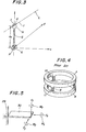
- Figure 1 is a side view showing an assembly operation by the assembly robot.
- numeral 1 indicates a hand of the assembly robot while numeral 2 indicates a grip provided with the free end of the hand 1.
- the drawing illustrates an operation in which a pin 3 is held by the grip 2 and the pin 3 is then inserted in a hole 5 of a counterpart 4 of the fitting.
- control of the hand 1 which control makes use of a multi-axis load sensor like the multi-axis load detector 6 may be applied not only in such a pin-inserting operation but also in a teaching operation for a robot.
- the teaching operation for a robot has generally be carried out by an expert, who inputs data, instructions, etc. in accordance with the details of work by operating keys on a teaching panel.
- such a teaching operation requires an expert and takes many hours.
- the teaching can be carried out without operating the keys on the teaching panel provided that a worker moves the hand 1 in accordance with an actual work routine by directly holding the hand 1, the robot is controlled by signals detected by the multi-axis load sensor 6 in the course of the above-described worker's teaching operation, and the control signals are stored. It is also worthy to mention that the above teaching operation can be successfully carried out in a short period of time by an ordinary worker who does not have any special knowledge.
- the multi-axis load sensor 6, which is utilized in such fields as described above, is required to have a function capable of detecting at least the magnitude, direction and line of action (which will be described later) of each load. Therefore, a discussion will next be made about matter required to detect these magnitude, direction and line of action of the load, based on the vectors of the force f shown in Figure 2. Now, let's think of coordinate axes x, y and z which are perpendicular to one another and determine, at their origin P, the magnitude, direction and point Q of action of a load f applied to the point Q of action. Let's also assume that the origin P and the point Q are connected to each other by a rigid member.
- the magnitude and direction of the load f can be obtained by synthesizing its components f x , fy and f z . Therefore, the magnitude and direction of the load f may be determined if each of the components in the above directions can be detected.
- detection values of the components in the above directions as F x , Fy and F z respectively, it is possible to determine the magnitude and direction of the load f if F x , Fy and F z (hereinafter called "Fi" as a whole), in which: are detected.
- the position of the point Q of action is to be determined. Supposing now that the distances from the origin P to the point Q of action in the directions of the x-axis, y-axis and z-axis be respectively lx, ly and l z and the moment components of the load f along the x-axis, y-axis and z-axis be M x , My and M z , the following relationship may be established among the distances k x , l y and l z , the moment components M x , My and M z (hereinafter called "Mi" as a whole) and the aforementioned force components F x , Fy and F z :
- numeral 6 is a multi-axis load sensor and letter G indicates a rod-like rigid body fixed on the multi-axis load sensor 6.
- the rod-like rigid body G extends on and along the z-axis.
- Letter H indicates a ball having a radius r and attached fixedly to the upper extremity of the rod-like rigid body G.
- the distance between the center of the multi-axis load sensor 6 and the center of the ball H is z o .
- the position (l x , l y , l z ) of the point Q of action which point Q is believed to be on the spherical surface of the ball H satisfies the following equation:
- the position (l x , £y, l z ) can be determined.
- the position of the point Q of action can still be obtained even if either one of the above six equations (i) - (iv) is not available.
- the position of the point Q of action may generally be determined so long as the line of action of the load can be determined, in other words, the force components Fi and moment components Mi can be detected, because information on the position, shape and spatial position of a body to which the load is being applied, for example, the hand of a robot, a body held by the hand or the like can be readily obtained.
- FIG. 4 is a perspective view illustrating one example of conventional multi-axis load sensors.
- numeral 7 indicates a first ring connected to the first rigid body (not illustrated).
- numeral 8 is a second ring which is connected to a second rigid body (not shown) and provided in face-to-face relationship with the first ring 7.
- Numeral 9 indicates flexible beams which connect the first ring 7 and second ring 8 to each other. Three flexible beams 9 are provided in total.
- Designated at numeral 10 is a tensile/compression force detection gauge applied on the inner surface of each flexible beam 9.
- Numeral 11 indicates a shear force detection gauge applied on the outer surface of each flexible beam 9.
- each of the flexible beams 9 is deformed in proportion to a load applied thereto.
- This deformation of each flexible beam 9 is detected by its respective detection gauges 10,11.
- the tensile/compression force detection gauges 10 detect principally the force components F x ,Fy and the moment component M z while the shear force detection gauges 11 detect mainly the force component F z and the moment components M x ,My.
- Detection of each of the components Fi and Mi is carried out by inputting a signal from each of the detection gauges 10,11 of each flexible beam 9 to a computer and then performing a prescribed operation.
- the components Fi and M i can thus be detected in the above manner, whereby permitting to know the magnitude, direction and line of action of the load applied to the first rigid body.
- the position of point of action of the load can also be determined if the position, shape and spatial position of the first rigid body are known.
- the multi-axis load sensor has the following structure.
- a hub is enclosed in a housing.
- a spider is provided with one end (upper end) of the hub.
- a plurality of arms extend out from the spider.
- the thus-extended arms are each connected to its corresponding detector which is provided fixedly on the housing, whereby detecting each deformation of the arm.
- a radially-extending flange member is attached to the other end (i.e. the lower end) of the hub.
- the flange member are connected to detectors which are also fixedly provided on the housing.
- the housing and hub are connected via a cantilevered bar fixed to the hub.
- This connection between the housing and the hub is established in such a way that they are allowed to move freely in directions parallel to the longitudinal axis of the cantilevered bar but the cantilevered bar resists against any displacements of the housing and hub in directions perpendicular to the longitudinal axis of the cantilevered bar.
- Such a structure is not different in nature from the multi-axis load sensor illustrated in Figure 4. Due to inclusion of connecting and/or attachment parts between the housing and hub, the hub and spiders, and the hub and flange member, these connecting and/or attachment parts add undesirable characteristics such as non-linear characteristic and hysteresis characteristics to the detection characteristics of the multi-axis load sensor. Where these undesirable characteristics appear to considerable extents, their influence cannot be completely wiped out even if any special operation is performed, whereby reducing the accuracy of the multi-axis load sensor to a significant extent. If such a multi-axis load sensor is applied to a robot, the controllability of the robot is considerably lowered.
- An object of this invention is thus to provide a multi -axis load sensor which can solve the above-described drawbacks of conventional multi-axis load sensors, minimize the interaction of detection to an extremely low level, enjoy good detection characteristics, and permits to increase both detection sensitivity and structural strength and rigidity.
- a multi-axis load sensor adapted to be connected between a first rigid member and a second rigid member so as to detect the magnitude, direction and point of action of each load to be transmitted between the first and second rigid members, which multi -axis load sensor comprises in combination:
- the multi-axis load sensor according to this invention can reduce interaction among detected signals to extremely low levels and make detection characteristics linear. In addition, it also permits to enhance both detection sensitivity and structural strength and rigidity. Moreover, it also provides so-called good "persistence" characteristics.
- FIG. 5 is a perspective view of a plate-like flexible beam.
- numeral 29 indicates a support portion and numeral 30 is the plate-like flexible beam supported as a cantilevered beam on the support portion 29.
- axes x,y,z which are perpendicular to one another.
- the force applied in the direction of the x-axis is F x
- the moment produced about the x-axis is M x
- the force applied in the direction of the y-axis is Fy
- the moment produced about the y-axis is My
- the force applied in the direction of the z-axis is F z
- the moment produced about the z-axis is M z .
- the plate -like flexible beam 30 is thinner in the direction of the z-axis but has far greater lengths in the directions of the x-axis and y-axis compared with the thicknesswise dimension.
- the plate-like flexible beam 30 is susceptible of undergoing deformation to the force F z and is also liable to develop deformation to the moment My which causes the plate-like flexible beam 30 to be deformed at its tip portion in the direction of the z-axis.
- the plate-like flexible beam 30 is extremely resistant to the forces F x ,F y and the moments M x ,My. It is the parallel plate structure and radial plate structure that have been constructed on the basis of such characteristics of the plate-like flexible beam 30.
- FIGS 6(a) through 6(c) are side views of a parallel plate structure.
- Designated at numeral 31 is a fixing portion supported on the support portion 29 and made of a rigid material.
- Numeral 32 indicates a displaceable portion which is located opposite to the support portion 29 and is also made of a rigid material.
- Numerals 33,33' indicate thin-walled portions connecting the fixing portion 31 and displaceable portion 32 together. These thin-walled portions 33,33' are arranged parallel to each other and may be considered to be equivalent to the plate-like flexible beam 30 illustrated in Figure 5. These thin -walled portions 33,33' can undergo deformation.
- a parallel plate structure 34 is thus constructed with the thin-walled portions 33,33' interposed at a central part thereof.
- the parallel plate structure 34 takes such a form as a square hole extends therethrough.
- a variety of forms may be contemplated for the hole defining the thin-walled portions 33,33'. This matter will however be described later in this specification.
- Letter K indicates a standard axis which extends through the displaceable portion 32 of the parallel plate structure 34.
- the standard axis K is apart by a suitable distance from the thin-walled portions 33,33' and may be considered as assuming a position near the point of action of the below -described force F z .
- Numerals 35,36,37,38 are respectively strain gauges provided at root portions of the thin-walled portions 33,33'.
- the parallel plate structure 34 having such a structure as described above, let's now assume that the force F z has been applied in the direction of the z-axis to the displaceable portion 32.
- the parallel plate structure 34 then develops a deformation because the thin-walled portions 33,33' are bent into substantially the same shape as illustrated in Figure 6(b). This deformation occurs readily as the lengths of the thin-walled portions 33,33' remain constant.
- the parallel plate structure 34 is resistant to the forces F x ,Fy applied respectively in the directions of the x-axis and y-axis and to the moment M x ,M z produced respectively about the x-axis and z-axis, similar to the plate-like flexible beam shown in Figure 5.
- the plate-like flexible beam 30 illustrated in Figure 5 is absolutely rigid against the forces F x ,Fy and the moment M z .
- the plate-like flexible beam 30 is more susceptible of undergoing deformation by the moment M x , compared with the above-mentioned three components. Owing to the modification into the parallel plate structure, the rigidity has also been enhanced against the moment M x .
- Figure 6(c) shows the deformation caused by the moment My. As apparent from the drawing, this deformation has elongated the thin-walled portion 33 but compressed the thin-walled portion 33'.
- this deformation is a deformation under which the thin -walled portion 33 is made different in length from the thin-walled portion 33', and develops internal forces in the thin-walled portions 33,33' along the x-axis. Therefore, the moment My which is required to develop such a deformation must be very large.
- the parallel plate structure 34 has a high degree of rigidity to the moment and hardly undergoes deformation under that moment.
- the parallel plate structure 34 shown in Figures 6(a) - 6(c) undergoes deformation by the force F z only and exhibits a high degree of rigidity to every other forces and moments.
- the displaceable portion 32 of the parallel plate structure 34 undergoes a displacement only by forces applied in the direction of the z-axis but does not show a displacement in any other directions.
- the displaceable portion 32 of the parallel plate structure 34 does not develop any rotary displacement.
- a bridge circuit is formed in such a way that the signs of the resultant values are opposite to each other, the small output portions of the deformation mode produced by the moment My are cancelled out, thereby allowing to obtain a correct signal proportional to the force F z from the bridge circuit.
- various detection means such as differential transformers capable of detecting displacements of the parallel plate structure, electro- capacitive detection means, eddy-current detection means, and the like, besides the above-mentioned strain gauges which detect strains.
- FIGS 7(a) through 7(c) are side views of the radial plate structure.
- numeral 29 indicates a support portion
- numeral 41 is a fixing portion supported by the support portion 29 and made of a rigid material
- numeral 42 indicates a displaceable portion located opposite to the support portion 29 and made of a rigid material.
- Numerals 43,43' indicate respectively thin-walled portions which connect the fixing portion 41 and displaceable portion 42 together. These thin-walled portions 43,43' correspond to the plate-like flexible beam 30 shown in Figure 5 and have deformable function.
- the thin-walled portions 43,43' extend radially from the displaceable portion 42 toward the fixing portion 41, with a point 0 as the center of the radial extension.
- the opening angle defined by the thin-walled portion 43 and the thin -walled portion 43' is indicated by 6.
- a radial plate structure 44 is constructed with such thin-walled portions 43,43' placed at a central part thereof. Since the thin-walled portions 43,43' extend radially, the radial plate structure 44 has such a shape as being formed by boring a trapezoidal hole through a rigid body, when seen in side view as illustrated in Figure 7(a). A variety of shapes may be contemplated for the hole which defines the thin-walled portions 43,43'. However, this matter will be described later in this specification.
- An axis which extends through the point O and is perpendicular to the sheet of the drawing, is employed as a standard axis.
- Numerals 45, 46,47,48 indicate respectively strain gauges provided to root portions of the thin-walled portions 43,43'.
- the radial plate structure 44 has a high degree of rigidity against the forces F x ,Fy applied in the directions of the x-axis and y-axis and the moments M x ,M z produced about the x-axis and z-axis, similar to the plate-like flexible beam shown in Figure 5. Therefore, it is difficult to cause the radial plate structure 44 to undergo a deformation by such forces.
- a discussion will be made on the deformation of the radial plate structure 44 when the force F z is applied in the direction of the z-axis to the displaceable portion 42.
- Figure 7(c) is referred to.
- the deformation by the force F z takes place in such a way that the thin -walled portion 43 is elongated but the thin-waller portion 43' is compressed. Therefore, the above deformation makes the lengths of the thin-walled portions 43,43' different from each other and involves axial forces in the planes of the thin-walled portions 43,43'.
- the force F z which is required to develop the deformation is very large. Namely, the axial plate structure 44 has a high degree of rigidity against the force F z and hardly undergoes deformation by the force F z .
- the radial plate structure 44 shown in Figure 7 undergoes deformation only when the moment My is applied. It has a high degree of rigidity against every other forces and moments. In other words, the displaceable portion 42 of the radial plate structure 44 is displaced only when the moment My is applied. It is displaced only very little when other forces or moments are applied.
- the opening angle 8 of the thin -walled portions 43,43' may take any desired value.
- the angle 6 is set at an excessively small value (0 ⁇ ⁇ « 90°)
- the rigidity against the force F z applied in the direction of the z-axis is lowered somewhat.
- the angle 8 is set at a too large value (90° « ⁇ ⁇ 180°)
- the rigidity against the force F x applied in the direction of the x-axis would be reduced to an unacceptable low level.
- strain detection means led by the strain gauges 45,46,47,48 are the same as the detection means in the parallel plate structure. Their description is thus omitted (strain detection means will not be described in the subsequent embodiments of this invention).
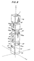
- FIG 8 is a perspective view of a 6-axis load sensor according to the first embodiment of this invention.
- numerals 52,53 are a first and second rigid bodies respectively.
- parallel plate structures and radial plate structures which are respectively the same as those shown in Figures 6 and 7, are connected one by one vertically along the z-axis with their x-axes and y-axes registered with the x-axis and y-axis, all of which z-axis, x-axis and y-axis are indicated by dashed lines in the drawing.
- each parallel plate structure and the thin-walled portions of each radial plate structure are respectively indicated by the same numerals 33,33',43,43' as used respectively in Figures 6 and 7.
- Strain detection means such as strain gauges are omitted in the drawing.
- Numeral 50 MZ indicates a radial plate structure which undergoes a deformation by the moment Mz about the z-axis.
- the radial plate structure 50 MZ is connected to the first rigid body 52.
- the letters " M Z" attached to the numeral 50 indicates the moment M z (this also applies to each of the subsequent moments and forces).
- Numeral 50 MY indicates a radial plate structure which undergoes a deformation by the moment My about the y-axis.
- Numeral 50 MX is a radial plate structure which undergoes a deformation by the moment M x about the x-axis.
- the radial plate structure 50MX is connected to the radial plate structure 50 MY .
- Numeral 51 FZ indicates a parallel plate structure which undergoes a deformation by the force F z applied in the direction of the z-axis.
- the parallel plate structure 51 FZ is connected to the radial plate structure 50 MX .
- Numeral 51 FY designates a parallel structure which undergoes a deformation by the force Fy applied in the direction of the y-axis.
- the parallel plate structure 51 FY is coupled with the parallel plate structure 51 FZ .
- Designated at numeral 51 FX is a parallel plate structure which undergoes a deformation by the force F x applied in the direction of the x-axis.
- the parallel plate structure 51 FX is connected to both of the parallel plate structure 51 FY and second rigid body 53.
- first and second rigid bodies 52,52, radial plate structures 50 MZ , 50 MY , 50 MX and parallel plate structures 51 FZ ,51 FY ,51 FX are constructed into a unitary block.
- letter J indicates a machining bore which was used to drill a through-hole for forming the radial plate structure 50 MZ .
- the standard axes of the radial plate structures 50 MZ ,50 M y,50 MX extend at right angles with one another.
- the standard axes of the parallel plate structures 51 FZ ,51 FY ,51 FX are arranged in such a way that they extend perpendicularly to one another.
- the radial plate structure 50 MZ Since the radial plate structure 50 MZ exhibits a high degree of rigidity against the force F z as mentioned above, the radial plate structure 50 MZ transmits the force F z as is to the next radial plate structure 50 MY without developing any deformation at its thin-walled portions 43,43'. Similarly, the radial plate structure 50 M y transmits the force F z to the next radial plate structure 50 MX without being deformed by the force F z . In the same manner, the radial plate structure 50 MX transmits the force F z to the next parallel plate structure 51 FZ without undergoing any deformation.
- the force F z causes the thin-walled portions 33,33' of the parallel plate structure 51 FZ to undergo deformation in accordance with the magnitude of the force F z .
- This deformation is detected by unillustrated strain detection means such as strain gauges or the like.
- the force F z is transmitted to the next parallel plate structure 51 FY while deforming the parallel plate structure 51 FZ .
- the parallel plate structure 51 FY is deformed only by the force Fy applied in the direction of the y-axis. Accordingly, the force F z is transmitted to the next parallel plate structure 51 FX without causing the parallel plate structure 51 FY to undergo any deformation.
- the force F Z is similarly transmitted from the parallel plate structure 51 FX to the second rigid body 53 without deforming the parallel plate structure 51 FX .
- the force component F z in the direction of the z-axis, out of the load applied to the first rigid body 52, is transmitted to the second rigid body 53 while deforming the parallel plate structure 51 FZ only.
- Other force components and moment components are also transmitted while causing only their corresponding parallel plate structures and radial plate structures to undergo deformation. The transmission of each force or moment component takes place in the same manner when a load is transmitted in the opposite direction, namely, from the second rigid body 53 to the first rigid body 51.
- three parallel plate structures are arranged in such a manner that their standard axes extend perpendicularly to one another and three radial plate structures are also arranged in such a way that their standard axes are normal to one another.
- the force components of an applied load in the directions of the axes and the moment components of the applied load about the axes are therefore detected respectively by different parallel plate structures and radial plate structures (in other words, by their corresponding specific parallel plate structures and radial plate structures). It is thus possible to lower the interaction among detected signals to an extremely small level.
- the 6-axis load sensor is formed into a unitary structure which is formed in its entirety from a rigid body. It is thus possible to enjoy good detection sensitivity and great strength.
- the 6-axis load sensor can provide so-called good "persistence" characteristics.
- the 6-axis load sensor can also avoid occurrence of undesirable characteristics such as non-linear characteristics and hysteresis characteristics because it does not contain any attachment or connecting portions.
- the initial object of "determining the line of action" can generally be achieved even by a 5-axis load sensor which is formed by omitting either one of the radial plate structures and parallel plate structures in the first embodiment.
- information on the force in the direction of a specific axis becomes indispensable depending on the direction of the line of action.
- the provision of all the radial plate structures and parallel plate structures in the first embodiment of this invention makes it possible to utilize information on a moment or force obtained by the unomitted radial or parallel plate structure. This additional information can avoid occurrence of operational errors and assures to obtain correct values.
- FIGS 9(a) through 9(d) are respectively side views of a parallel plate structure and radial plate structure employed in the second embodiment.
- Figures 9(a) through 9(d) are respectively side views of a parallel plate structure and radial plate structure employed in the second embodiment.
- the same parts or elements as those illustrated in Figures 6 and 7 are indicated by like reference numerals and their explanation is thus omitted.
- a parallel plate structure 39 is shown.
- this parallel plate structure 39 has been formed by connecting two of the parallel plate structure shown in Figure 6(a) side by side with only one displaceable portion 32 commonly shared by both of the constituent parallel plate structures.
- the parallel plate structure 39 shows a high degree of rigidity against the force components F x ,Fy applied respectively in the directions of the x-axis and y-axis to the displaceable portion 32 and the moment components M x ,My,M z applied respectively about the x-axis, y-axis and z-axis to the displaceable portion 32, for the same reasons as explained in the description of the parallel plate structure 34 shown in Figure 6. Therefore, the parallel plate structure 39 can hardly be deformed by such force or moment components. Consequently, the parallel plate structure 39 has such characteristics that it undergoes deformation only by the force component F z but has high rigidity against every other force components and moment components and is hence hardly deformable by such other force components or moment components.
- FIG 9(c) there is illustrated a radial plate structure 49.
- the radial plate structure 49 has such a structure, similar to the parallel plate structure 39, that two of the radial plate structure 44 depicted in Figure 7(a) are connected side by side at the displaceable portion 42.
- the opening angle ⁇ of the thin-walled portions 43,43' at one side is equal to the opening angle 8 of the thin-walled portions 43,43' at the other side.
- a point O is located at the center of the displaceable portion 42.
- a line, which passes through the point O and is perpendicular to the drawing sheet, is the standard axis of the radial plate structure 49.
- the radial plate structure 49 however exhibits a high degree of rigidity against the force components F x ,F y ,F z applied respectively in the directions of the x-axis, y-axis and z-axis to the displaceable portion 42 and the moment components M x ,M z applied about the x-axis and y-axis to the displaceable portion 42, for the same reasons as mentioned in the description of the radial plate structure 44 depicted in Figure 7. Accordingly, the radial plate structure is hardly deformed by these force components and moment components. Consequently, the radial plate structure 49 has such characteristics that it undergoes deformation only by the moment component My but has high rigidity against every other force components and moment components and can hardly be deformed by such force and moment components.
- the parallel plate structure 39 and radial plate structure 49 illustrated respectively in Figures 9(a) and 9(c) permit their thin-walled portions 33,33', 43,43' to undergo more correct deformation compared with the single cantilevered parallel plate structure 34 and radial plate structure 44 illustrated respectively in Figure 6(a) and Figure 7(a), since the displaceable portions 32,42, to which loads are applied, make up central portions of structures supported at both ends thereof.
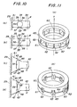
- Figures 10(a) through 10(d) are side views of further structural examples of the parallel plate structure and radial plate structure respectively.
- the parallel plate structure 39 shown in Figure 9(a) has a shape defining square holes
- the radial plate structure 49 depicted in Figure 9(c) has a shape forming trapezoidal holes.
- the thin-walled portions 33,33' of the parallel plate structure 39 are formed by the square holes
- the thin-walled portions 43,43' of the radial plate structure 49 are formed by the trapezoidal holes.
- the formation of the thin-walled portions 33,33', 43,43' is not limited to the formation of square holes and trapezoidal holes only. They may be formed by holes of other shapes.
- numeral 54 indicates a circular hole formed through a rigid body.
- the thin -walled portions 33,33' of the parallel plate structure are formed by the circular hole 54.
- numeral 55 indicates small circular holes formed respectively in an upper and lower edge portions.
- the circular holes 55 are precisely opposed to each other.
- Numeral 56 is a linear slot communicating these two small circular holes 55.
- numeral 57 indicates a substantially elliptical hole formed through a rigid body and extending substantially to the upper and lower edges.
- the thin-walled portions 43,43' of the radial plate structure are formed by the above elliptical hole 57.
- numeral 58 indicates small circular holes formed in a precisely-opposing relation in an upper and lower edge portions of a rigid body.
- numeral 59 indicates a linear slot communicating these two circular holes.
- Figures ll(a) and ll(b) are perspective views of further modifications of the radial plate structure.
- numeral 60 indicates a ring-shaped first rigid body and numeral 61 indicates a ring-shaped second rigid body having substantially the same dimensions as the first rigid body 60.
- Numeral 62 indicates a number of thin-walled portions connecting the first rigid body 60 and the second rigid body 61 together. The thin-walled portions 62 are arranged radially and with the same interval on the peripheries of the first rigid body 60 and second rigid body 61. The opening angle between adjacent two thin-walled portions 62 is the same.
- the first rigid body 60 or the second rigid body 61 is susceptible of undergoing a deformation by a moment about the z-axis but shows a high degree of rigidity against every other moment components and force components.
- the structure shown in Figure 11(a) is a radial plate structure having characteristics similar to those illustrated in Figures 7 and 9(c).
- Figure 11(b) illustrates a radial plate structure having thin-walled portions which are defined by elliptical holes and sector holes.
- numeral 63 indicates elliptical holes.
- the thin -walled portions are formed by a plural set of two mutually-opposing elliptical holes 63.
- the elliptical hole 63 in each set is connected to the elliptical hole 63 of the adjacent set via a sector hole 64.
- the first rigid body 60 and the second rigid body 61 are connected by the plurality of thin-walled portions 62 only, thereby forming substantially the same radial plate structure as that shown in Figure ll(a).
- the thin -walled portions are arranged with the same opening angle and interval. It is however not always necessary to arrange the thin-walled portion with the same interval. They may be arranged with different intervals without encountering any problem or inconvenience.
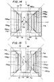
- FIG 12 is a perspective view of a 6-axis load sensor according to the second embodiment of this invention.
- Figure 13 is a plan view of the 6-axis load sensor of Figure 12, a part of which 6-axis load sensor is shown in cross-section.
- Figure 14 is a side view of the 6-axis load sensor, a part of which is shown in cross-section along line XIV-XIV of Figure 13.
- Figure 15 is a side view of the 6-axis load sensor, a part of which is shown in cross-section along line XV-XV of Figure 13.
- the 6-axis load sensor according to the second embodiment of this invention will hereinafter be described, referring principally to Figure 12.
- the 6-axis load sensor is constructed substantially of five load-responsive portions A, B, C, D and E.
- letter C indicates a central load-responsive portion assuming a central position in the 6-axis load sensor.
- Letter A indicates a first load-responsive portion extending out in a direction from the central load -responsive portion C.
- Designated at letter B is a second load-responsive portion which extends out from the central load-responsive portion in a direction opposite to the first load-responsive portion A.
- Letter D means a third load-responsive portion which extends out from the central load-responsive portion C in a direction perpendicular to both first and second load-responsive portions A,B.
- Letter E indicates a fourth load-responsive portion which extends out from the central load-responsive portion C in a direction opposite to the third load-responsive portion D.
- Numerals 71a, 71b, 71d and 71e indicate respectively outer wall portions of the load-responsive portions A, B, D and E.
- Numeral 72 indicates a ring-shaped upper member, one half portion of which is omitted in Figure 12.
- the ring-shaped upper member 72 is connected to the outer wall portions 71a,71b of the first and second load-responsive portions A,B. (The ring-shaped upper member 72 is not connected to the outer wall portions 71d,71e.)
- the ring-shaped upper member 72 is connected to a rigid body which is not illustrated in the drawing.
- Numeral 73 indicates a ring-shaped lower member, which is connected to the outer wall portions 71d,71e of the third and fourth load-responsive portions D,E.
- the ring-shaped lower member 73 is not connected to the outer wall portions 71a,71b.
- the ring-shaped lower member 72 is connected to another rigid body which is not illustrated in the drawing.
- the above-described load-responsive portions A,B,C,D,E, the ring-shaped upper member 72 and the ring-shaped lower member 73 are formed into an integral structure.
- the central point of the above 6-axis sensor (said central point being present in the central load-responsive portion C) be P
- a coordinate axis extending out from the central point P toward both first and second load-responsive portions A,B be a y-axis
- a coordinate axis extending out from the central point P toward both the third and fourth load-responsive portions D,E be an x-axis
- a coordinate axis extending perpendicularly to the y-axis and x-axis and passing through the central load -responsive portion C be a z-axis.
- the structure of the first load-responsive portion A will be explained first of all.
- the first load-responsive portion A is constructed, in order from the outer wall portion 71a toward the central load-responsive portion C, a parallel plate structure 74A FXI a radial plate structure 75A MX and a radial plate structure 75A MZ -
- the parallel plate structure 74A FX includes thin -walled portions 77,77' formed by a rectangular hole 76 extending along the z-axis. These thin-walled portions 77,77' are equivalent to the thin-walled portions 33,33' illustrated in Figure 9(a).
- the thin-walled portions 77,77' undergo deformations in accordance with the magnitude and direction of the force component F x when the force component F x is applied in the direction of the x-axis to the parallel plate structure 74A FX .
- the resulting strains are detected as signals by means of detection means such as strain gauges (which are not shown in the drawing. Detection means will be omitted in subsequent embodiments) provided at root portions of the thin-walled portions 77,77'.
- the first load -responsive portion A does not undergo any deformation by force components in the directions of the y-axis and z-axis and moment components about the x-axis, y-axis and z-axis, and shows high rigidity against such force and moment components.
- the parallel plate structure 74A FX is deformed by force components applied in the direction of the x-axis only, thereby detecting the force components.
- the radial plate structure 75A MX has radially-disposed thin-walled portions 79,79' which are defined by a trapezoidal hole 78 extending in the direction of the x-axis.
- the thin-walled portions 79,79' are formed, as illustrated in Figure 14, in such a way that they form an angle 8 1 with respect to the point P.
- These thin-walled portions 79,79' correspond to the thin-walled portions 43,43' illustrated in Figure 9(c).
- the thin-walled portions 79,79' undergo deformations in response to the moment M x , thereby detecting the moment M x .
- the radial plate structure 75A MX is capable of undergoing deformation only by the moment M x but exhibits high rigidity against the other moment components and force components.
- the radial plate structure 75A MZ has radially -disposed thin-walled portions 81,81' formed by a trapezoidal hole 80 which extends in the direction of the z-axis.
- the thin-walled portions 81,81' are formed, as shown in Figure 13, in such a way that they form an angle 6 2 with respect to the point P. They are equivalent to the thin-walled portions 43,43' depicted in Figure 9(c).
- the moment M z is applied about the z-axis to the radial plate structure 75A MZ ; the thin-walled portions 81,81' undergo deformations in response to the moment M z , thereby detecting the moment M z .
- the radial plate structure 75A MZ develops deformation only by the moment M z but exhibits high rigidity against the other moment components and force components.
- numerals 74A FX ,75A MX ,75A MZ which also appear in the drawings, will be explained.
- Numeral 74 indicates that each structure designated by this numeral is a parallel plate structure.
- numeral 75 indicates that each structure designated by this numeral is a radial plate structure.
- Letter A indicates that a structure bearing this letter is located in the first load-responsive portion A.
- letters FX attached to a structure indicates that the structure can selectively detect the force F x applied in the direction of the x-axis.
- Letters MX means that a structure bearing these letters can selectively detect the moment M x about the x-axis.
- Letters MZ means it is the moment M z about the z-axis that a structure bearing these letters can selectively detect.
- Each of structures in each load -responsive portion in the following embodiments of this invention is attached with a numeral and letters in accordance with the above-mentioned standard.
- a through -bore 82 is formed in the direction of the z-axis through a central part of the central load-responsive portion C.
- a rectangular through-hole 83 is formed from the outside to the through-bore 82.
- thin-walled portions 84,84' which are parallel to each other.
- a parallel plate structure unit 74C FZ is formed by the thin-walled portions 84,84'.
- the parallel plate structure unit 74C FZI When the force component F z is applied in the direction of the z-axis to the parallel plate structure unit 74C FZI the thin-walled portions 84,84' undergo deformations in response to the force component F z , thereby detecting the force component F z .
- the parallel plate structure unit 74C FZ is deformed only by the force component F z but shows high rigidity against any other force components and moments.
- the structure of the second load-responsive portion B takes a form symmetric to the structure of the first load-responsive portion A.
- the second load -responsive portion B has, in order from the outer wall portion 71b toward the central load-responsive portion C, a parallel plate structure 74B FX , a radial plate structure 75B MX and a radial plate structure 75B MZ .
- the structure of the third load -responsive portion D is formed in such a way that it is equipped with a parallel plate structure 74D FY , a radial plate structure 75D MY and a radial plate structure 75D MZ in order from its outer wall portion 71d toward the central load-responsive portion C.
- the fourth load-responsive portion E has a structure symmetric to the structure of the third load -responsive portion D and is equipped, in order from the outer wall portion 71e toward the central load -responsive portion C, a parallel plate structure 74E FY , a radial plate structure 75E M y and a radial plate structure 75E MZ .
- These parallel structures 74B FX ,74D FY ,74E FY and radial plate structures 75B MX , 75B MZ ,75D MY ,75D MZ are equal to those contained in the first load-responsive portion A and their detailed explanation is thus omitted herein.
- the parallel plate structure and radial plate structures in each of the load -responsive portions A - E detect the force components F x ,F y ,F z of the load in the directions of the x-axis, y-axis and z-axis as well as the moment components M x ,My,M z of the load about the x-axis, y-axis and z-axis.
- the force component Fy is transmitted from the ring-shaped upper member 72 to the first and second load-responsive portions A,B.
- the parallel plate structures 74A FX ,74B FX and radial plate structures 75A MX ,75A MZ ,75B MX ,75B MZ are not deformed by the force component Fy and the force component Fy is transmitted as is to the central load-responsive portion C.
- the parallel plate structure unit 74C FZ of the central load-responsive portion C is not deformed by the force component Fy.
- the force component Fy is transmitted as is to the third and fourth load -responsive portions D,E.
- the force component Fy which has been transmitted to the load-responsive portions D,E, is transmitted via the radial plate structures 75D MZ ,75E MZ ,75D MY ,75E MY to the parallel plate structures 74D FY ,74E FY without causing the radial plate structures to undergo any deformation.
- These parallel plate structures 74D FY ,74E FY are deformed by the force component Fy with magnitudes and directions proportional to the force component Fy, thereby detecting the force component Fy.
- the forth component Fy which has deformed the parallel plate structures 74D FY ,74E FY , is then transmitted via the ring-shaped lower member 73 to the unillustrated rigid body.
- Other force and moment components are detected in the same manner by the corresponding parallel plate structures and radial plate structures.
- the radial plate structures adapted to detect the moment component M z are provided in two sets, namely, one in the first load-responsive portion and another in the second load-responsive portion, and one in the third load -responsive portion and another in the fourth load -responsive portion.
- the moment component Mz can be detected by either one of the sets.
- the radial plate structure shown in Figure 11(a) or 11(b) may be provided in place of the ring-shaped upper or lower member so that the radial plate structures 75A MZ ,75B MZ ,75D MZ ,75E MZ may be omitted.
- the central load-responsive portion may also be formed by two sets of parallel plate structures, namely, one parallel plate structure arranged in the direction of the y-axis and another parallel plate structure arranged in the direction of the x-axis, to detect the force component F z .
- the above embodiment contains the central load-responsive portion and the first to fourth load-responsive portions which extend out from the central load -responsive portion in the form of a cross and the parallel plate structure(s) and radial plate structure(s) are formed with their standard axes crossing perpendicularly to each of the load-responsive portions. Therefore, all the force components of an applied load in the directions of the axes and moment components of the applied load about the axes can be detected respectively by their corresponding specific parallel plate structures and radial plate structures, thereby making it possible to reduce interactions of detected signals to extremely low levels upon detecting such force and moment components.
- the detector Since the detector is formed in its entirety by forming as a unitary structure portions having elasticity in their corresponding load directions in parts of a rigid body, it is possible to achieve good detection sensitivity and large strength and rigidity. Moreover, the load sensor has a symmetric structure as a whole, its rigidity is well-balanced in all directions, thereby providing so-called good "persistence" characteristics. Owing to the exclusion of attachment or connecting parts, the load sensor can avoid the occurrence of such undesirable characteristics as non-linear characteristics and/or hysteresis characteristics. It is thus clear that the load sensor may be designed so as to make each output from each axis thereof have linear characteristics.
- Signals which pertain to interactions and may still be generated at extremely low levels, may be corrected by a simple conversion (a conversion making use of a linear equation). As a result, it permits to obtain detection signals with high accuracy within sufficiently-short operation time periods, even when applied, for example, in order to perform the real time control of a robot.
- the above -mentioned "persistence" characteristics are still better than those of the former embodiment, because the load sensor has a symmetrical structure as a whole and the standard axes are all coincided at the point P. Similar to the advantageous effects brought about by the previous embodiment, the load sensor of this embodiment still contains the radial plate structure or parallel plate structure although it may be omitted. Thus, it is possible to detect directly a moment or force component pertaining to the unomitted axis, thereby successfully avoiding occurrence of operational errors and providing correct values.
- 6-axis load sensors which are each adapted to detect the force and moment components of an applied load in the directions of all axes.
- 6-axis load sensor or 5-axis load sensor it is possible to determine the magnitude, direction and line of action of a load applied to a body connected thereto. If there are certain limited conditions as for the position of point of action, or the magnitude or the direction of each applied force, one or more of radial plate structures and/or parallel plate structures may be removed in accordance with the limited conditions from the 6-axis or 5-axis load sensor so as to convert it into a 4-axis, 3-axis or 2-axis load sensor. Exemplary loads accompanied by such limited conditions that permit use of a 4-axis load sensor and 2-axis load sensor respectively will next be described briefly with reference to Figures 16 and 17.
- Figure 16 is a drawing illustrating a detection by a 4-axis load sensor.
- the load applied to the point Q of action and the position of the point Q of action can thus be determined provided that either three of the force components F X ,F y and moment components M x ,M y are detected.
- the radial plate structures 50 MZ ,50 MX may be removed from the embodiment shown in Figure 8 so as to form a 4-axis load sensor.
- the radial plate structures 75A MX ,75B MX ,75A MZ ,75B MZ ,75D MZ ,75E MZ may be omitted to form a 4-axis load sensor.
- Figure 17 illustrates a detection by means of a 2-axis load detector.
- a load f x is applied in the direction of the x-axis to a point Q on the z-axis.
- the load f x it is only necessary to determine the position l z of the point Q of action on the z-axis and the load f x . It is therefore required only to determine the force component F x and moment component My.
- all plate structures other than the radial plate structure 50 MY and parallel plate structure 51 FX may be removed to form a 2-axis load sensor.
- all plate structures other than the parallel plate structures 74A FX ,74B FX and radial plate structures 75D MY ,75E MY may be omitted to form a 2-axis load sensor.
- the present invention is not necessarily limited to a 6-axis load sensor or 5-axis load sensor but some of its parallel plate structures and radial plate structures may be omitted to form a 4-axis load sensor, 3-axis load sensor or 2-axis load sensor.
- a multi-axis load sensor has at least one radial plate structure and at least one of a parallel and radial plate structures having, as their standard axes, axes perpendicular to the standard axis of the former radial plate structure. It is clear that the magnitude and direction of a load may be calculated by force components Fi only, for example, the force components F X ,F y or the force components F x ,F y ,F z but the line of action of the load cannot be determined by such force components Fi only.
- the orthogonal coordinate system as a coordinate system constituted by the x-axis, y-axis and z-axis as the orthogonal coordinate system is usual and practical.
- the coordinate system is not always required to be an orthogonal coordinate system.
- the basic function is not different at all even in the case of a multi-axis load sensor imaged in an oblique coordinate system.
- the standard axes of the parallel plate structures and radial plate structures are arranged perpendicularly to one another.
- the standard axes may however be allowed to cross along the axes of a given oblique coordinate system. It is possible to carry out desired detections without encountering any problem or inconvenience even by means of a multi-axis load sensor constructed in the above manner.
- the multi-axis load sensor of this invention has a unitary structure of a radial plate structure and either one or both of a radial and parallel plate structures having, as their standard axes, axes which are neither coincident with nor parallel to the standard axis of the former radial plate structure; or a radial plate structure and a plurality of radial and/or parallel plate structures having, as their standard axes, axes which are neither coincident with nor parallel to the standard axis of the former radial plate structure.
Landscapes
- Physics & Mathematics (AREA)
- General Physics & Mathematics (AREA)
- Force Measurement Appropriate To Specific Purposes (AREA)
- Manipulator (AREA)
Applications Claiming Priority (2)
| Application Number | Priority Date | Filing Date | Title |
|---|---|---|---|
| JP58168385A JPS6062497A (ja) | 1983-09-14 | 1983-09-14 | 多軸力センサ |
| JP168385/83 | 1983-09-14 |
Publications (3)
| Publication Number | Publication Date |
|---|---|
| EP0139307A2 true EP0139307A2 (de) | 1985-05-02 |
| EP0139307A3 EP0139307A3 (en) | 1986-02-05 |
| EP0139307B1 EP0139307B1 (de) | 1989-01-18 |
Family
ID=15867122
Family Applications (1)
| Application Number | Title | Priority Date | Filing Date |
|---|---|---|---|
| EP84200591A Expired EP0139307B1 (de) | 1983-09-14 | 1984-04-26 | Kraftsensor mit mehreren Achsen |
Country Status (4)
| Country | Link |
|---|---|
| US (2) | US4628745A (de) |
| EP (1) | EP0139307B1 (de) |
| JP (1) | JPS6062497A (de) |
| DE (1) | DE3476263D1 (de) |
Cited By (8)
| Publication number | Priority date | Publication date | Assignee | Title |
|---|---|---|---|---|
| EP0173405A3 (en) * | 1984-08-30 | 1987-01-28 | Yotaro Hatamura | Multi-axis load sensor |
| EP0256392A1 (de) * | 1986-08-12 | 1988-02-24 | Siemens Aktiengesellschaft | Messanordnung zum Erfassen von Kräften und Momenten |
| GB2200467A (en) * | 1986-09-24 | 1988-08-03 | Avery Ltd W & T | Load cell |
| EP0177284B1 (de) * | 1984-09-29 | 1991-09-11 | Fujitsu Limited | Kraftmessvorrichtung |
| DE102012012988A1 (de) * | 2012-06-29 | 2014-04-17 | Liebherr-Verzahntechnik Gmbh | Vorrichtung zur automatisierten Handhabung von Werkstücken |
| US9002507B2 (en) | 2012-06-29 | 2015-04-07 | Liebherr-Verzahntechnik Gmbh | Apparatus for the automated detection and removal of workpieces |
| US9289897B2 (en) | 2012-06-29 | 2016-03-22 | Liebherr-Verzahntechnik Gmbh | Apparatus for the automated removal of workpieces arranged in a container |
| US9492926B2 (en) | 2012-06-29 | 2016-11-15 | Liebherr-Verzahntechnik Gmbh | Apparatus for the automated handling of workpieces |
Families Citing this family (31)
| Publication number | Priority date | Publication date | Assignee | Title |
|---|---|---|---|---|
| CH665287A5 (fr) * | 1985-12-17 | 1988-04-29 | Scaime | Capteur a jauge de contrainte pour la mesure de forces. |
| JPS62274230A (ja) * | 1986-05-22 | 1987-11-28 | ロ−ド・コ−ポレイシヨン | 過負荷保護付き力/トルクセンサ− |
| JP2599709B2 (ja) * | 1986-10-28 | 1997-04-16 | サペル | 力及び/又は偶力のセンサデバイス |
| US4911024A (en) * | 1989-02-10 | 1990-03-27 | Barry Wright Corporation | Force sensing |
| US5056361A (en) * | 1990-09-18 | 1991-10-15 | The United States Of America As Represented By The Administrator Of The National Aeronautics And Space Administration | Dual strain gage balance system for measuring light loads |
| US5481184A (en) * | 1991-12-31 | 1996-01-02 | Sarcos Group | Movement actuator/sensor systems |
| US5992212A (en) * | 1996-11-07 | 1999-11-30 | Roger D. Sims, P.E. | Device for determining coefficient of friction and level of lubrication |
| WO1999028716A1 (en) * | 1997-11-26 | 1999-06-10 | Litens Automotive Partnership | Load sensor |
| US6536292B1 (en) * | 1998-02-04 | 2003-03-25 | The Goodyear Tire & Rubber Company | Triaxial force pin sensor array |
| US6253626B1 (en) * | 1999-09-02 | 2001-07-03 | Rs Technologies, Ltd. | Three-axis transducer body and strain gage arrangement therefor |
| US6584385B1 (en) * | 1999-10-01 | 2003-06-24 | Innovative Design Solutions, Inc. | Vehicle leveling assembly |
| US6324918B1 (en) | 2000-06-05 | 2001-12-04 | Center For Tribology, Inc. | Bidirectional force sensor |
| WO2003036249A1 (en) * | 2001-10-04 | 2003-05-01 | Center For Tribology, Inc. | Method and device for measuring forces |
| DE10330947B4 (de) * | 2003-07-08 | 2015-10-29 | Schenck Process Gmbh | Kreuzfederelement |
| EP1719991A4 (de) * | 2004-02-04 | 2007-04-11 | Ono Sokki Co Ltd | Drehmomentmessvorrichtung |
| KR100854674B1 (ko) * | 2006-12-14 | 2008-08-28 | 삼성중공업 주식회사 | 모형선박의 러더에 작용하는 힘 계측장치 |
| US20130090763A1 (en) * | 2008-01-25 | 2013-04-11 | The Trustees Of Columibia University In The City Of The City Of New York | Systems and methods for force sensing in a robot |
| US7784363B2 (en) * | 2008-09-30 | 2010-08-31 | Gm Global Technology Operations, Inc. | Phalange tactile load cell |
| DE102009056209A1 (de) * | 2009-11-28 | 2011-07-07 | Kurt 75242 Stähle | Aktuatorvorrichtung mit Kraftsensor |
| US8276466B2 (en) * | 2010-03-31 | 2012-10-02 | Kulite Semiconductor Products, Inc. | Two or three-axis shear load cell |
| CN101813536A (zh) * | 2010-04-19 | 2010-08-25 | 南京航空航天大学 | 一种两分量大载荷力传感器 |
| JP5836633B2 (ja) * | 2011-05-10 | 2015-12-24 | キヤノン株式会社 | 力覚センサ及び組立ロボット |
| DE102014209109A1 (de) | 2014-05-14 | 2015-11-19 | Robert Bosch Gmbh | Kraftaufnehmer, Anordnung mit mehreren Kraftaufnehmern und Verwendung der Anordnung |
| DE102015215099B3 (de) * | 2015-08-07 | 2016-12-08 | Dr. Doll Holding Gmbh | Kraft-Moment-Sensor sowie Dehnmessstreifen-System und Platinenanordnung für einen derartigen Kraft-Moment-Sensor |
| WO2017112929A1 (en) * | 2015-12-23 | 2017-06-29 | Mts Systems Corporation | Transducer sensor body |
| GB201617097D0 (en) * | 2016-10-07 | 2016-11-23 | King S College London | Multi-Axis force sensor |
| DE102017102343B4 (de) * | 2017-02-07 | 2022-04-28 | Wittenstein Se | Sensoranordnung zur Kraft- oder Drehmomentmessung und ein Verfahren zur Herstellung derselben |
| JP6817875B2 (ja) * | 2017-04-14 | 2021-01-20 | 日本電産コパル電子株式会社 | 力覚センサ |
| GB2592411B (en) | 2020-02-27 | 2022-08-17 | Dyson Technology Ltd | Force sensing device |
| JP2023527179A (ja) | 2020-06-28 | 2023-06-27 | シャンハイ・フレクシブ・ロボティクス・テクノロジー・カンパニー・リミテッド | 軸力センサアセンブリ、ロボットグリッパー及びロボット |
| US20240418590A1 (en) * | 2023-06-19 | 2024-12-19 | Illinois Tool Works Inc. | Six degree of freedom load cell body |
Family Cites Families (9)
| Publication number | Priority date | Publication date | Assignee | Title |
|---|---|---|---|---|
| US3867838A (en) * | 1971-01-28 | 1975-02-25 | Hofmann Maschf Geb | Instrument hub for the measurement of forces and/or moments |
| US3939704A (en) * | 1974-08-07 | 1976-02-24 | The Bendix Corporation | Multi-axis load cell |
| US4094192A (en) * | 1976-09-20 | 1978-06-13 | The Charles Stark Draper Laboratory, Inc. | Method and apparatus for six degree of freedom force sensing |
| DE2727704C3 (de) * | 1977-06-21 | 1982-12-09 | Deutsche Forschungs- und Versuchsanstalt für Luft- und Raumfahrt e.V., 5000 Köln | Kraft-Drehmoment-Fühler |
| JPS5888631A (ja) * | 1981-11-24 | 1983-05-26 | Yotaro Hatamura | スラスト・トルク検出素子 |
| US4478089A (en) * | 1982-06-29 | 1984-10-23 | International Business Machines Corporation | Tri-axial force transducer for a manipulator gripper |
| CA1237739A (en) * | 1982-09-21 | 1988-06-07 | Kazuo Asakawa | Supporting device |
| EP0117334A3 (de) * | 1982-11-09 | 1986-01-15 | EMI Limited | Für mehrere Kraftkomponenten empfindliche Vorrichtung |
| FR2545606B1 (fr) * | 1983-05-06 | 1985-09-13 | Hispano Suiza Sa | Capteur de torseur de forces |
-
1983
- 1983-09-14 JP JP58168385A patent/JPS6062497A/ja active Pending
-
1984
- 1984-04-26 DE DE8484200591T patent/DE3476263D1/de not_active Expired
- 1984-04-26 EP EP84200591A patent/EP0139307B1/de not_active Expired
- 1984-04-30 US US06/605,212 patent/US4628745A/en not_active Expired - Lifetime
-
1986
- 1986-05-27 US US06/867,221 patent/US4712431A/en not_active Expired - Lifetime
Cited By (10)
| Publication number | Priority date | Publication date | Assignee | Title |
|---|---|---|---|---|
| EP0173405A3 (en) * | 1984-08-30 | 1987-01-28 | Yotaro Hatamura | Multi-axis load sensor |
| EP0177284B1 (de) * | 1984-09-29 | 1991-09-11 | Fujitsu Limited | Kraftmessvorrichtung |
| EP0256392A1 (de) * | 1986-08-12 | 1988-02-24 | Siemens Aktiengesellschaft | Messanordnung zum Erfassen von Kräften und Momenten |
| GB2200467A (en) * | 1986-09-24 | 1988-08-03 | Avery Ltd W & T | Load cell |
| GB2200467B (en) * | 1986-09-24 | 1990-08-08 | Avery Ltd W & T | Load cell |
| DE102012012988A1 (de) * | 2012-06-29 | 2014-04-17 | Liebherr-Verzahntechnik Gmbh | Vorrichtung zur automatisierten Handhabung von Werkstücken |
| US9002507B2 (en) | 2012-06-29 | 2015-04-07 | Liebherr-Verzahntechnik Gmbh | Apparatus for the automated detection and removal of workpieces |
| US9289897B2 (en) | 2012-06-29 | 2016-03-22 | Liebherr-Verzahntechnik Gmbh | Apparatus for the automated removal of workpieces arranged in a container |
| US9302396B2 (en) | 2012-06-29 | 2016-04-05 | Liebherr-Verzahntechnik Gmbh | Apparatus for the automated handling of workpieces |
| US9492926B2 (en) | 2012-06-29 | 2016-11-15 | Liebherr-Verzahntechnik Gmbh | Apparatus for the automated handling of workpieces |
Also Published As
| Publication number | Publication date |
|---|---|
| EP0139307B1 (de) | 1989-01-18 |
| DE3476263D1 (en) | 1989-02-23 |
| JPS6062497A (ja) | 1985-04-10 |
| EP0139307A3 (en) | 1986-02-05 |
| US4628745A (en) | 1986-12-16 |
| US4712431A (en) | 1987-12-15 |
Similar Documents
| Publication | Publication Date | Title |
|---|---|---|
| EP0139307B1 (de) | Kraftsensor mit mehreren Achsen | |
| EP0154728B1 (de) | Lastdetektor | |
| US4576053A (en) | Load detector | |
| US6792815B2 (en) | Multiaxis ring load cell | |
| EP1707934A1 (de) | Sechsachsiger Drucksensor | |
| EP0177919A2 (de) | Verfahren zum Kalibrieren der Transformationsmatrix eines Kraftsensors | |
| US4674339A (en) | Multi-axis load sensor | |
| GB1587009A (en) | Multi-axis load cells | |
| JP2549289B2 (ja) | 多分力検出器 | |
| US20060107761A1 (en) | Multi-axis load cell body | |
| JPS6095331A (ja) | 力・モ−メントセンサ− | |
| JPH05149811A (ja) | 6軸力覚センサ | |
| US20050120809A1 (en) | Robotic force sensing device | |
| US4138884A (en) | Multi-axis load cell | |
| JPH0640039B2 (ja) | 力検出装置 | |
| EP0171123B1 (de) | Lastfühler | |
| JPS6333647B2 (de) | ||
| JP3265539B2 (ja) | 多分力計 | |
| JPS61145426A (ja) | 荷重検出装置 | |
| JPS61145427A (ja) | 荷重検出装置 | |
| JPH01119731A (ja) | 多軸力覚センサ | |
| JPH0668501B2 (ja) | 加速度計 | |
| US20240337545A1 (en) | Multi-axis load cell body | |
| CN117740224A (zh) | 一种多通道输出的二分量力传感器 | |
| JPH0582535B2 (de) |
Legal Events
| Date | Code | Title | Description |
|---|---|---|---|
| PUAI | Public reference made under article 153(3) epc to a published international application that has entered the european phase |
Free format text: ORIGINAL CODE: 0009012 |
|
| AK | Designated contracting states |
Designated state(s): DE NL SE |
|
| PUAL | Search report despatched |
Free format text: ORIGINAL CODE: 0009013 |
|
| AK | Designated contracting states |
Designated state(s): DE NL SE |
|
| 17P | Request for examination filed |
Effective date: 19860801 |
|
| 17Q | First examination report despatched |
Effective date: 19870918 |
|
| GRAA | (expected) grant |
Free format text: ORIGINAL CODE: 0009210 |
|
| AK | Designated contracting states |
Kind code of ref document: B1 Designated state(s): DE NL SE |
|
| PG25 | Lapsed in a contracting state [announced via postgrant information from national office to epo] |
Ref country code: SE Effective date: 19890118 Ref country code: NL Effective date: 19890118 |
|
| REF | Corresponds to: |
Ref document number: 3476263 Country of ref document: DE Date of ref document: 19890223 |
|
| NLV1 | Nl: lapsed or annulled due to failure to fulfill the requirements of art. 29p and 29m of the patents act | ||
| PLBE | No opposition filed within time limit |
Free format text: ORIGINAL CODE: 0009261 |
|
| STAA | Information on the status of an ep patent application or granted ep patent |
Free format text: STATUS: NO OPPOSITION FILED WITHIN TIME LIMIT |
|
| 26N | No opposition filed | ||
| PGFP | Annual fee paid to national office [announced via postgrant information from national office to epo] |
Ref country code: DE Payment date: 20010418 Year of fee payment: 18 |
|
| PG25 | Lapsed in a contracting state [announced via postgrant information from national office to epo] |
Ref country code: DE Free format text: LAPSE BECAUSE OF NON-PAYMENT OF DUE FEES Effective date: 20021101 |