EP0139312A2 - Appareil pour la mesure sélective des ions dans un liquide - Google Patents
Appareil pour la mesure sélective des ions dans un liquide Download PDFInfo
- Publication number
- EP0139312A2 EP0139312A2 EP84201154A EP84201154A EP0139312A2 EP 0139312 A2 EP0139312 A2 EP 0139312A2 EP 84201154 A EP84201154 A EP 84201154A EP 84201154 A EP84201154 A EP 84201154A EP 0139312 A2 EP0139312 A2 EP 0139312A2
- Authority
- EP
- European Patent Office
- Prior art keywords
- isfet
- electrode
- liquid
- low
- coupled
- Prior art date
- Legal status (The legal status is an assumption and is not a legal conclusion. Google has not performed a legal analysis and makes no representation as to the accuracy of the status listed.)
- Granted
Links
- 150000002500 ions Chemical class 0.000 title claims abstract description 29
- 239000007788 liquid Substances 0.000 title claims abstract description 25
- 230000001681 protective effect Effects 0.000 claims abstract description 18
- 230000005669 field effect Effects 0.000 claims abstract description 6
- 239000003990 capacitor Substances 0.000 claims description 10
- 239000004020 conductor Substances 0.000 claims description 3
- 230000000694 effects Effects 0.000 description 13
- 230000005684 electric field Effects 0.000 description 6
- 239000012212 insulator Substances 0.000 description 5
- 239000008280 blood Substances 0.000 description 3
- 210000004369 blood Anatomy 0.000 description 3
- 238000004519 manufacturing process Methods 0.000 description 3
- 229910021420 polycrystalline silicon Inorganic materials 0.000 description 3
- 229920005591 polysilicon Polymers 0.000 description 3
- 230000002411 adverse Effects 0.000 description 2
- XAGFODPZIPBFFR-UHFFFAOYSA-N aluminium Chemical compound [Al] XAGFODPZIPBFFR-UHFFFAOYSA-N 0.000 description 2
- 230000015556 catabolic process Effects 0.000 description 2
- 238000010586 diagram Methods 0.000 description 2
- BSYNRYMUTXBXSQ-UHFFFAOYSA-N Aspirin Chemical compound CC(=O)OC1=CC=CC=C1C(O)=O BSYNRYMUTXBXSQ-UHFFFAOYSA-N 0.000 description 1
- 239000004743 Polypropylene Substances 0.000 description 1
- RTAQQCXQSZGOHL-UHFFFAOYSA-N Titanium Chemical compound [Ti] RTAQQCXQSZGOHL-UHFFFAOYSA-N 0.000 description 1
- AZDRQVAHHNSJOQ-UHFFFAOYSA-N alumane Chemical group [AlH3] AZDRQVAHHNSJOQ-UHFFFAOYSA-N 0.000 description 1
- 229910052782 aluminium Inorganic materials 0.000 description 1
- 239000013590 bulk material Substances 0.000 description 1
- 238000003869 coulometry Methods 0.000 description 1
- 230000008878 coupling Effects 0.000 description 1
- 238000010168 coupling process Methods 0.000 description 1
- 238000005859 coupling reaction Methods 0.000 description 1
- 230000001419 dependent effect Effects 0.000 description 1
- 239000003822 epoxy resin Substances 0.000 description 1
- 230000001939 inductive effect Effects 0.000 description 1
- 239000000463 material Substances 0.000 description 1
- 238000005259 measurement Methods 0.000 description 1
- 229910052751 metal Inorganic materials 0.000 description 1
- 239000002184 metal Substances 0.000 description 1
- 229910044991 metal oxide Inorganic materials 0.000 description 1
- 150000004706 metal oxides Chemical class 0.000 description 1
- 238000012986 modification Methods 0.000 description 1
- 230000004048 modification Effects 0.000 description 1
- 229920000647 polyepoxide Polymers 0.000 description 1
- -1 polypropylene Polymers 0.000 description 1
- 229920001155 polypropylene Polymers 0.000 description 1
- 239000004065 semiconductor Substances 0.000 description 1
- 229910052710 silicon Inorganic materials 0.000 description 1
- 239000010703 silicon Substances 0.000 description 1
- 229910001220 stainless steel Inorganic materials 0.000 description 1
- 239000010935 stainless steel Substances 0.000 description 1
- 239000010936 titanium Substances 0.000 description 1
- 229910052719 titanium Inorganic materials 0.000 description 1
Images

Classifications
-
- G—PHYSICS
- G01—MEASURING; TESTING
- G01N—INVESTIGATING OR ANALYSING MATERIALS BY DETERMINING THEIR CHEMICAL OR PHYSICAL PROPERTIES
- G01N27/00—Investigating or analysing materials by the use of electric, electrochemical, or magnetic means
- G01N27/26—Investigating or analysing materials by the use of electric, electrochemical, or magnetic means by investigating electrochemical variables; by using electrolysis or electrophoresis
- G01N27/403—Cells and electrode assemblies
- G01N27/414—Ion-sensitive or chemical field-effect transistors, i.e. ISFETS or CHEMFETS
- G01N27/4148—Integrated circuits therefor, e.g. fabricated by CMOS processing
Definitions
- the present invention relates to an apparatus for selectively measuring ions in a liquid and more specifically to a protection system for protecting an ion sensor of the apparatus.
- the apparatus comprises a measuring circuit including a chemically selective ion sensor in the form of an ion-sensitive field effect transistor (ISFET), a reference electrode, and an amplifier.
- ISFET ion-sensitive field effect transistor
- Measuring apparatus for measuring ions in a liquid using an ISFET have been previously proposed. See for example the Johnson et al U.S. Patent No. 4,020,830. Such an apparatus includes a measuring circuit and an ISFET immersed in a liquid for selectively measuring the ion activity in the liquid. Different ISFETS are used for measuring different ion activities, such as for example pH, pK, pNa.
- this electrical field which may be caused by external influences exceeds a maximum value, dielectrical breakdwon may occur in the gate insulator region and the ISFET may be damaged.
- the gate insulator consists of a multi-layer system (for example of combinations of Si0 2 -S i 3 N 4 or Si02 - A1 2 0 3 )
- an unduly strong electrical field may produce still another effect, namely a shift in the threshold voltage of the ISFET, which may be permanent or which is only corrected after a long period of time. This results in the apparatus being permanently or temporarily out of order since the calibration of the apparatus is now incorrect.
- an electrical field may be created by external influences or effects such as, for example, from electrosurgical apparatus, heart defibrillation apparatus, electromagnetic influences resulting from switching inductive elements on or off, and also from electrostatic voltages generated during the manufacture of the ISFET sensor or during use of the apparatus in practice.
- ISFET's however have no metallic gate electrode in a way similar to a MOSFET to which a protective element can be connected.
- the measuring apparatus of the present invention includes a protection system constructed and arranged and connected to substantially fully cancel or neutralize the external influences or effects or their affect on a measuring apparatus including an ISFET without the protection system having an adverse affect on the behavior of the ISFET sensor under normal operating conditions.
- an apparatus for selectively measuring ions in a liquid comprising a measuring circuit including a chemically sensitive ion sensor in the form of an ion sensitive field effect transistor (ISFET), a reference electrode, and an amplifieer, characterized in that said measuring circuit is connected to a protection system comprising at least one electrode connected via a low-impedance contact to the liquid and coupled to said ISFET by a protective element having a low impedance for high voltages and a high resistance to low voltages.
- ISFET ion sensitive field effect transistor
- an ISFET chip characterized by having an electrode on the chip in as closely spaced relationship as possible to the gate region of the ISFET.
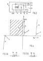
- a measuring circuit 10 including a protection system 12 for a measuring apparatus 14 (Figs. 1,2 and 3) constructed according to the teachings of the present invention.
- the circuit 10 includes an ion-sensitive field effect transistor (ISFET or ISFET sensor) 16 having a drain 18 coupled to one input 20 of a amplifier 22 and a source 24 coupled to another input 26 of the amplifier 22 which has an output 28 that has an output signal indicative of the con centration of ions in a liquid (such as blood) 30.
- ISFET ion-sensitive field effect transistor
- the circuit 10 includes a reference electrode 32 which applies a reference voltage to liquid 30 so that the gate region 34 is electrically connected to the amplifier 22, thus enabling control of the drain-source current I DS of the ISFET 16 in a manner similar to that used with MOSFET's.
- the voltage that is experienced by the ISFET consists of a portion that is dependent on the ion activity in the liquid to which the ISFET is specifically sensitive, and of the externally applied voltage V .
- a change in ion concentration gives rise to a change in drain-source current. This change in drain-source current can be compensated for by adjusting the externally applied voltage V .
- the relationship between ion activity and the developed voltage is known.
- the amplifier measures the drain-source current constantly and corrects V RB for changes in that current in order to keep it constant.
- the output voltage of the amplifier is proportional to the changes in V RB .
- a protection system or guard circuit 40 is coupled between the source 24 and the liquid 30 and includes a first electrode 42 coupled to the source 24 through a first protection circuit 44 and a second electrode 46 coupled to the source 24 through a second protection circuit 48 both having a high resistance to low voltages and a low impedance to high voltages.
- the first electrode 42 is preferably made of metal, for example, of stainless steel having good blood compatibility, or of titanium.
- the first electrode 42 should be made of a conductive material having good blood compatibility and having a surface area sufficiently large to provide a low-impedance contact with the liquid 30 when the ISFET 16 and reference electrode 32 are immersed into the liquid 30 being investigated.
- the first electrode 42 serves to protect the ISFET 16 from high A.C. voltages which occur, for example, with the use of an electrosurgical apparatus.
- the first electrode 42 is coupled to the source 24 by one or more protective elements in the protection circuit 44, such as by a diode 50, two bucking or reverse polarity series connected diodes 51, 52 and/or a MOSFET 54, which become conductive outside the operative range of the ISFET 16, for example, a Zener diode or an avalanche diode or a MOSFET having a high threshold voltage to the measuring circuit, and/or a capacitor 56.
- the first electrode 42 can be coupled to the source 24 by a mechanical switch 58 serving as a protective element.
- the protective elements 50-58 can, of course, be coupled to any contact which is in a low-impedance connection with the source 24 of the ISFET 16, for example, the drain 18 or bulk contact 36.
- the second electrode 46 may take the form of a current conducting fork, strip or ring, and preferably a ring 62 (Fig. 3) of a current conducting material, such as aluminum orpolysilicon, applied around the gate region 34 of the ISFET 16 and coupled by one or more protective elements in protection circuit 48, such as by a diode 64, two bucking or reverse polarity series connected diodes 65, 66, and/or a MOSFET 68 which become conductive outside the operative range of the ISFET 16, for example, a Zener diode or an avalanche diode or a MOSFET having a high threshold voltage to the measuring circuit.
- the second electrode 46 is as closely spaced to the gate region 34 of the ISFET as possible.
- any leakage current which may be present within the operative range of the ISFET 16 gives rise to a shift in the reference electrode potential equal to the product of leakage current and impedance. This shift contributes to the voltage that is experienced by the ISFET 16 and accordingly has a negative effect on the accuracy of the measurement, which becomes unacceptable if the leakage current comes to be in excess of an acceptable limit, for example, is more than lOnA. Therefore, within the operative range of the ISFET 16, the DC currents which may pass through the protective elements should accordingly be kept below the acceptable limit.
- the second electrode 46 thus connected to the measuring circuit 10, provides protection of the ISFET sensor 16 from electrostatic voltages, which may occur during manufacture of the sensor 16 or also during use thereof.
- the protective element is diode 64, MOSFET 68 and/or the diodes 65,66, these elements can be used in combination for both the first and the second electrode and may be arranged on the ISFET chip.
- capacitor 56 it is important that the capacitance of the capacitor 56 is sufficiently high in order that the impedance may be low enough for the frequency of the spurious A.C. voltage applied, for example, that applied in electrosurgical operations.
- a capacitance of 100 nF or more is generally satisfactory for this purpose.
- the capacitor 56 may be included in the amplifier 22.
- the mechanical switch 58 When the mechanical switch 58 is used, it is effective to use a relay switch (not shown) for this purpose, which is activated by the source of interference and is maintained in the activated state for the time the interference lasts.
- a relay switch (not shown) for this purpose, which is activated by the source of interference and is maintained in the activated state for the time the interference lasts.
- the protection system or guard circuit 40 can be constructed so that the first electrode 42 is connected to the capacitor 56 and the second electrode 46 is connected to the diode 64, the MOSFET 68 and/or the diodes 65,66.
- the apparatus 14 can be mounted in a catheter 80 where the reference electrode 32 is mounted in a terminal or tip part 82.
- the first electrode 42 is then realized by a metallic ring 42 spaced slightly rearwardly of the tip part 82.
- the ring electrode 42 has a surface area of about 1 cm 2 which provides a low-impedance contact with the liquid 30 (Fig. 1) in which the catheter 80 is to be immersed.
- the ring 42 can be electrically connected to a terminal on the ISFET chip (90-Fig. 3) through a polypropylene capacitor 56 having a capacitance of 100 nF, which in this case is included in the ISFET amplifier circuit.
- the ISFET sensor 16 is housed or mounted by an epoxy resin within a housing portion 84 of the catheter 80 located rearwardly of the ring electrode 42.
- FIG. 3 A plan view of a chip 90 containing the ISFET 16 which can be mounted in housing portion 84 of the catheter 80 is shown in Fig. 3.
- the chip 90 includes a source 91 and a drain 92 diffused in bulk 93 of the chip 90 and provided with a source bulk contact element 24,36 and a drain contact element 18.
- a protective electrode, i.e. the second electrode 46 is realized by a aluminum ring 62 which is electrically connected to a protective circuit 48 which is diffused in the bulk 93 of the ISFET chip 90.
- the second electrode 46/aluminum ring 62 is applied around the gate region 34 on the chip 90.
- the potential V of the reference electrode 32 relative to the bulk 36 of the ISFET 16 is plotted along the horizontal axis, and the current intensity along the vertical axis with I D being the diode current and I DS being the drain-source current.
- the hatched area in the graph represents the operative range of the ISFET sensor 16.
- the letter A designates the point of diode breakdown and the letter B represents the diode pass characteristic.
- the protective element can be a combination of two diodes (51, 52 or 65, 66) connected in anti-series or reverse polarity to each other.
- Such diodes may be two Zener diodes 101, 102 in a connection as represented in Fig. 5a or two Zener diodes 103, 104 in a connection as represented in Fig. 5b.
- the graph of I shown in Fig. 4 is modified to the graph of I shown in phantom in Fig. 4.
- the protection system or guard circuit 40 constructed according to the teachings of the present invention offers adequate protection from external effects or influences resulting from electromagnetic sources of interference which may be encountered in the biomedical and industrial fields, for example, in cases in which the ISFET sensor 16 and apparatus 14 is used in cooperation with electrosurgical apparatus or heart defibrillation apparatus.
- the protection further extends to the danger of the occurrence of electrostatic voltages as may occur during the manufacture of the ISFET sensor 16 or also during use of the apparatus 14 in practice.
- the protection offered by the guard circuit 40 according to the present invention is effective in combination with all types of housings of the ISFET sensor 16, for example, the case of catheter tip sensors, flow cells and other types of housings.
Landscapes
- Chemical & Material Sciences (AREA)
- Engineering & Computer Science (AREA)
- Microelectronics & Electronic Packaging (AREA)
- Health & Medical Sciences (AREA)
- Life Sciences & Earth Sciences (AREA)
- Electrochemistry (AREA)
- General Health & Medical Sciences (AREA)
- Chemical Kinetics & Catalysis (AREA)
- Computer Hardware Design (AREA)
- Physics & Mathematics (AREA)
- Analytical Chemistry (AREA)
- Biochemistry (AREA)
- Molecular Biology (AREA)
- General Physics & Mathematics (AREA)
- Immunology (AREA)
- Pathology (AREA)
- Measurement Of The Respiration, Hearing Ability, Form, And Blood Characteristics Of Living Organisms (AREA)
- Investigating Or Analyzing Materials By The Use Of Electric Means (AREA)
- Investigating Or Analyzing Non-Biological Materials By The Use Of Chemical Means (AREA)
Applications Claiming Priority (4)
| Application Number | Priority Date | Filing Date | Title |
|---|---|---|---|
| NL8302963 | 1983-08-24 | ||
| NL8302963A NL8302963A (nl) | 1983-08-24 | 1983-08-24 | Inrichting voor het selectief meten van ionen in een vloeistof. |
| US641911 | 1984-08-16 | ||
| US06/641,911 US4589970A (en) | 1983-08-24 | 1984-08-16 | Apparatus for selectively measuring ions in a liquid |
Related Child Applications (2)
| Application Number | Title | Priority Date | Filing Date |
|---|---|---|---|
| EP88200725.5 Division-Into | 1984-08-23 | ||
| EP19880200725 Division EP0307973B1 (fr) | 1983-08-24 | 1984-08-23 | Transistor à effet de champ sensible aux ions pouvant être utilisé dans un appareil comportant un circuit de mesure pour mesurer sélectivement les ions dans un liquide |
Publications (3)
| Publication Number | Publication Date |
|---|---|
| EP0139312A2 true EP0139312A2 (fr) | 1985-05-02 |
| EP0139312A3 EP0139312A3 (en) | 1985-06-12 |
| EP0139312B1 EP0139312B1 (fr) | 1989-11-08 |
Family
ID=26645886
Family Applications (2)
| Application Number | Title | Priority Date | Filing Date |
|---|---|---|---|
| EP19880200725 Expired - Lifetime EP0307973B1 (fr) | 1983-08-24 | 1984-08-23 | Transistor à effet de champ sensible aux ions pouvant être utilisé dans un appareil comportant un circuit de mesure pour mesurer sélectivement les ions dans un liquide |
| EP19840201154 Expired EP0139312B1 (fr) | 1983-08-24 | 1984-08-23 | Appareil pour la mesure sélective des ions dans un liquide |
Family Applications Before (1)
| Application Number | Title | Priority Date | Filing Date |
|---|---|---|---|
| EP19880200725 Expired - Lifetime EP0307973B1 (fr) | 1983-08-24 | 1984-08-23 | Transistor à effet de champ sensible aux ions pouvant être utilisé dans un appareil comportant un circuit de mesure pour mesurer sélectivement les ions dans un liquide |
Country Status (4)
| Country | Link |
|---|---|
| EP (2) | EP0307973B1 (fr) |
| JP (2) | JPH0765982B2 (fr) |
| CA (1) | CA1228894A (fr) |
| DE (2) | DE3480430D1 (fr) |
Cited By (1)
| Publication number | Priority date | Publication date | Assignee | Title |
|---|---|---|---|---|
| RU2134877C1 (ru) * | 1994-01-19 | 1999-08-20 | Ханивелл Инк. | Защита от электростатического разряда датчиков на ионно-селективных полевых транзисторах |
Families Citing this family (13)
| Publication number | Priority date | Publication date | Assignee | Title |
|---|---|---|---|---|
| AT398133B (de) * | 1989-06-26 | 1994-09-26 | Jachimowicz Artur Dipl Ing | Ionenselektive elektrodenanordnung |
| US5944970A (en) * | 1997-04-29 | 1999-08-31 | Honeywell Inc. | Solid state electrochemical sensors |
| JP2987343B2 (ja) | 1997-05-09 | 1999-12-06 | 文一 庄司 | トラス構造、それに使用する部材およびその製造方法 |
| US6117292A (en) * | 1998-05-06 | 2000-09-12 | Honeywell International Inc | Sensor packaging having an integral electrode plug member |
| US6153070A (en) * | 1998-05-07 | 2000-11-28 | Honeywell Inc | Sensor packaging using heat staking technique |
| US6604401B2 (en) | 1999-02-08 | 2003-08-12 | Bunichi Shoji | Truss structure, structural members thereof, and a method of manufacture therefor |
| US7790112B2 (en) * | 2006-03-30 | 2010-09-07 | Council of Scientific & Industual Research | Biosensor to determine potassium concentration in human blood serum |
| CN101131375B (zh) * | 2006-08-23 | 2010-05-12 | 中国科学院电子学研究所 | 一种离子敏场效应传感器专用高精度放大器电路 |
| JP4901535B2 (ja) * | 2007-03-02 | 2012-03-21 | 株式会社東芝 | 生体関連物質測定装置 |
| CN101855543B (zh) * | 2007-12-27 | 2013-05-08 | 株式会社堀场制作所 | 极性有机溶剂的水分或有机酸的含量的测定方法及其装置 |
| GB2484339B (en) * | 2010-10-08 | 2016-12-21 | Dnae Group Holdings Ltd | Electrostatic discharge protection |
| DE102013106032A1 (de) * | 2013-06-11 | 2014-12-11 | Endress + Hauser Conducta Gesellschaft für Mess- und Regeltechnik mbH + Co. KG | Sensor zur Erfassung einer Analytkonzentration |
| JP6296880B2 (ja) * | 2014-04-23 | 2018-03-20 | バイオセンサー株式会社 | 測定装置および測定方法 |
Family Cites Families (8)
| Publication number | Priority date | Publication date | Assignee | Title |
|---|---|---|---|---|
| JPS5530312B2 (fr) * | 1975-01-16 | 1980-08-09 | ||
| US4020830A (en) * | 1975-03-12 | 1977-05-03 | The University Of Utah | Selective chemical sensitive FET transducers |
| US4325097A (en) * | 1979-09-17 | 1982-04-13 | General Semiconductor Industries, Inc. | Four terminal pulse suppressor |
| JPS56153247A (en) * | 1980-04-28 | 1981-11-27 | Kuraray Co Ltd | Measuring circuit for ion sensor |
| US4397714A (en) * | 1980-06-16 | 1983-08-09 | University Of Utah | System for measuring the concentration of chemical substances |
| JPS5715459A (en) * | 1980-07-01 | 1982-01-26 | Fujitsu Ltd | Semiconductor integrated circuit |
| JPS5737876A (en) * | 1980-08-20 | 1982-03-02 | Hitachi Ltd | Semiconductor integrated circuit apparatus |
| JPS6216677Y2 (fr) * | 1980-08-25 | 1987-04-27 |
-
1984
- 1984-08-23 EP EP19880200725 patent/EP0307973B1/fr not_active Expired - Lifetime
- 1984-08-23 CA CA000461659A patent/CA1228894A/fr not_active Expired
- 1984-08-23 DE DE8484201154T patent/DE3480430D1/de not_active Expired
- 1984-08-23 EP EP19840201154 patent/EP0139312B1/fr not_active Expired
- 1984-08-23 DE DE19843486239 patent/DE3486239T2/de not_active Expired - Lifetime
- 1984-08-24 JP JP59175288A patent/JPH0765982B2/ja not_active Expired - Fee Related
-
1993
- 1993-03-01 JP JP5064703A patent/JPH0774794B2/ja not_active Expired - Fee Related
Cited By (1)
| Publication number | Priority date | Publication date | Assignee | Title |
|---|---|---|---|---|
| RU2134877C1 (ru) * | 1994-01-19 | 1999-08-20 | Ханивелл Инк. | Защита от электростатического разряда датчиков на ионно-селективных полевых транзисторах |
Also Published As
| Publication number | Publication date |
|---|---|
| DE3486239T2 (de) | 1994-03-03 |
| DE3486239D1 (de) | 1993-12-09 |
| JPH06308078A (ja) | 1994-11-04 |
| JPH0774794B2 (ja) | 1995-08-09 |
| EP0139312B1 (fr) | 1989-11-08 |
| JPH0765982B2 (ja) | 1995-07-19 |
| EP0139312A3 (en) | 1985-06-12 |
| JPS6089744A (ja) | 1985-05-20 |
| EP0307973B1 (fr) | 1993-11-03 |
| EP0307973A2 (fr) | 1989-03-22 |
| DE3480430D1 (en) | 1989-12-14 |
| EP0307973A3 (fr) | 1991-03-20 |
| CA1228894A (fr) | 1987-11-03 |
Similar Documents
| Publication | Publication Date | Title |
|---|---|---|
| US4589970A (en) | Apparatus for selectively measuring ions in a liquid | |
| EP0139312B1 (fr) | Appareil pour la mesure sélective des ions dans un liquide | |
| KR100358534B1 (ko) | Isfet센서의정전기방전보호장치및방법 | |
| US4508613A (en) | Miniaturized potassium ion sensor | |
| US4397714A (en) | System for measuring the concentration of chemical substances | |
| JP2572697B2 (ja) | 低インピーダンス過大電圧保護回路 | |
| US4851104A (en) | Instrument for potentiometric electrochemical measurements | |
| KR930010102B1 (ko) | 전류 검출 기능 부착 트랜지스터 | |
| EP2568282A1 (fr) | Détecteur sensible aux ions | |
| JPS60113143A (ja) | Isfet測定装置および方法 | |
| US5944970A (en) | Solid state electrochemical sensors | |
| KR20040111631A (ko) | 반도체 장치, 소스와 드레인 사이의 전압차 측정 방법 및반도체 장치 보호 방법 | |
| Wilhelm et al. | pH sensor based on differential measurements on one pH-FET chip | |
| JP3509623B2 (ja) | 半導体スイッチ素子チップの温度検出構造および温度検出装置並びに半導体リレー | |
| EP0280230B1 (fr) | Instrument pour mesure de potentiel électrochimique dans une solution d'un électrolyte | |
| JP3982090B2 (ja) | 半導体イオンセンサ | |
| US5241213A (en) | Buried zener diode having auxiliary zener junction access path | |
| JPH042250B2 (fr) | ||
| JP7508306B2 (ja) | プローブを測定システムに結合するためのインターフェイスユニット | |
| JP3685542B2 (ja) | 帯電量測定装置 | |
| JPS5914763Y2 (ja) | イオン式煙感知器 | |
| JPS6031732A (ja) | 生体用電極 | |
| EP0148771A2 (fr) | Détecteur de proximité capacitif | |
| JPS56158478A (en) | Semiconductor device | |
| KR100199928B1 (ko) | 차동형 반도체 화학센서 |
Legal Events
| Date | Code | Title | Description |
|---|---|---|---|
| PUAI | Public reference made under article 153(3) epc to a published international application that has entered the european phase |
Free format text: ORIGINAL CODE: 0009012 |
|
| PUAL | Search report despatched |
Free format text: ORIGINAL CODE: 0009013 |
|
| AK | Designated contracting states |
Designated state(s): DE FR GB IT NL |
|
| AK | Designated contracting states |
Designated state(s): DE FR GB IT NL |
|
| 17P | Request for examination filed |
Effective date: 19850513 |
|
| 17Q | First examination report despatched |
Effective date: 19861120 |
|
| GRAA | (expected) grant |
Free format text: ORIGINAL CODE: 0009210 |
|
| AK | Designated contracting states |
Kind code of ref document: B1 Designated state(s): DE FR GB IT NL |
|
| ITF | It: translation for a ep patent filed | ||
| REF | Corresponds to: |
Ref document number: 3480430 Country of ref document: DE Date of ref document: 19891214 |
|
| ET | Fr: translation filed | ||
| PLBE | No opposition filed within time limit |
Free format text: ORIGINAL CODE: 0009261 |
|
| STAA | Information on the status of an ep patent application or granted ep patent |
Free format text: STATUS: NO OPPOSITION FILED WITHIN TIME LIMIT |
|
| 26N | No opposition filed | ||
| ITTA | It: last paid annual fee | ||
| REG | Reference to a national code |
Ref country code: GB Ref legal event code: IF02 |
|
| PGFP | Annual fee paid to national office [announced via postgrant information from national office to epo] |
Ref country code: FR Payment date: 20030530 Year of fee payment: 20 |
|
| PGFP | Annual fee paid to national office [announced via postgrant information from national office to epo] |
Ref country code: GB Payment date: 20030820 Year of fee payment: 20 |
|
| PGFP | Annual fee paid to national office [announced via postgrant information from national office to epo] |
Ref country code: NL Payment date: 20030831 Year of fee payment: 20 |
|
| PGFP | Annual fee paid to national office [announced via postgrant information from national office to epo] |
Ref country code: DE Payment date: 20031021 Year of fee payment: 20 |
|
| PG25 | Lapsed in a contracting state [announced via postgrant information from national office to epo] |
Ref country code: GB Free format text: LAPSE BECAUSE OF EXPIRATION OF PROTECTION Effective date: 20040822 |
|
| PG25 | Lapsed in a contracting state [announced via postgrant information from national office to epo] |
Ref country code: NL Free format text: LAPSE BECAUSE OF EXPIRATION OF PROTECTION Effective date: 20040823 |
|
| REG | Reference to a national code |
Ref country code: GB Ref legal event code: PE20 |
|
| NLV7 | Nl: ceased due to reaching the maximum lifetime of a patent |