EP0139437A2 - Dispositif pour positionner une partie de chenille - Google Patents
Dispositif pour positionner une partie de chenille Download PDFInfo
- Publication number
- EP0139437A2 EP0139437A2 EP84306049A EP84306049A EP0139437A2 EP 0139437 A2 EP0139437 A2 EP 0139437A2 EP 84306049 A EP84306049 A EP 84306049A EP 84306049 A EP84306049 A EP 84306049A EP 0139437 A2 EP0139437 A2 EP 0139437A2
- Authority
- EP
- European Patent Office
- Prior art keywords
- rails
- track
- trolley
- guide table
- cylinder
- Prior art date
- Legal status (The legal status is an assumption and is not a legal conclusion. Google has not performed a legal analysis and makes no representation as to the accuracy of the status listed.)
- Granted
Links
- 238000006073 displacement reaction Methods 0.000 claims abstract description 8
- 239000000463 material Substances 0.000 description 3
- 229910000831 Steel Inorganic materials 0.000 description 1
- 239000010959 steel Substances 0.000 description 1
Images

Classifications
-
- B—PERFORMING OPERATIONS; TRANSPORTING
- B23—MACHINE TOOLS; METAL-WORKING NOT OTHERWISE PROVIDED FOR
- B23P—METAL-WORKING NOT OTHERWISE PROVIDED FOR; COMBINED OPERATIONS; UNIVERSAL MACHINE TOOLS
- B23P19/00—Machines for simply fitting together or separating metal parts or objects, or metal and non-metal parts, whether or not involving some deformation; Tools or devices therefor so far as not provided for in other classes
-
- B—PERFORMING OPERATIONS; TRANSPORTING
- B21—MECHANICAL METAL-WORKING WITHOUT ESSENTIALLY REMOVING MATERIAL; PUNCHING METAL
- B21L—MAKING METAL CHAINS
- B21L19/00—Appurtenances for chain-making not restricted to any particular process
-
- B—PERFORMING OPERATIONS; TRANSPORTING
- B21—MECHANICAL METAL-WORKING WITHOUT ESSENTIALLY REMOVING MATERIAL; PUNCHING METAL
- B21L—MAKING METAL CHAINS
- B21L21/00—Tools or implements for repairing chains using metal-working operations, e.g. for detaching deformed chain links
-
- B—PERFORMING OPERATIONS; TRANSPORTING
- B25—HAND TOOLS; PORTABLE POWER-DRIVEN TOOLS; MANIPULATORS
- B25H—WORKSHOP EQUIPMENT, e.g. FOR MARKING-OUT WORK; STORAGE MEANS FOR WORKSHOPS
- B25H1/00—Work benches; Portable stands or supports for positioning portable tools or work to be operated on thereby
- B25H1/14—Work benches; Portable stands or supports for positioning portable tools or work to be operated on thereby with provision for adjusting the bench top
- B25H1/18—Work benches; Portable stands or supports for positioning portable tools or work to be operated on thereby with provision for adjusting the bench top in inclination
-
- B—PERFORMING OPERATIONS; TRANSPORTING
- B62—LAND VEHICLES FOR TRAVELLING OTHERWISE THAN ON RAILS
- B62D—MOTOR VEHICLES; TRAILERS
- B62D55/00—Endless track vehicles
- B62D55/32—Assembly, disassembly, repair or servicing of endless-track systems
-
- Y—GENERAL TAGGING OF NEW TECHNOLOGICAL DEVELOPMENTS; GENERAL TAGGING OF CROSS-SECTIONAL TECHNOLOGIES SPANNING OVER SEVERAL SECTIONS OF THE IPC; TECHNICAL SUBJECTS COVERED BY FORMER USPC CROSS-REFERENCE ART COLLECTIONS [XRACs] AND DIGESTS
- Y10—TECHNICAL SUBJECTS COVERED BY FORMER USPC
- Y10S—TECHNICAL SUBJECTS COVERED BY FORMER USPC CROSS-REFERENCE ART COLLECTIONS [XRACs] AND DIGESTS
- Y10S59/00—Chain, staple, and horseshoe making
- Y10S59/901—Cross pin
Definitions
- the present invention relates to an apparatus for displacing or incrementally advancing a length of articulated track or chain for example, a track such as a caterpillar track employed on a bulldozer etc..
- the apparatus may be required to displace the length of track towards track presses for disassembling the track or, after the links have been assembled or reassembled to a line, it may be required to move the track away from track presses step by step.
- the operational efficiency in assembling, reassembling or disassembling a length of track will vary substantially in dependence on the performance of the apparatus for displacing it. Furthermore, in order to assure that an intended operation is performed safely on the track presses it is necessary for the apparatus displacing the length of track to move it accurately towards and away from the presses.
- the setting member is a threaded spindle, stationary with respect to the rails, on which the stops are mounted by way of correspondingly tapped holes.
- each stop comprises a pair of nuts with an elastic member located between them.
- the elastic member may be made of rubber or the like material and is preferably in the form of an O-ring.
- each of the rails for guiding movement of the trolley may have a U-shaped section and the trolley preferably carries rollers which are located in the U-shaped sections.
- the actuators comprise pneumatically or hydraulically operated cylinders.
- the top end of the first actuator is preferably pivotally connected to the rails, while its bottom end is preferably pivotally connected to the frame structure.
- the foremost end of the second actuator is preferably operatively connected to the trolley, while its rearmost end is connected to the rails.
- a system for disassembling, assembling and/or reassembling a length of track or chain comprising an apparatus A for displacing the track and an opposed pair of track presses B, are located on each side of the apparatus A at one end.
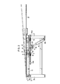
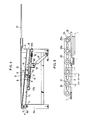
- the structure of the apparatus A is shown in more detail in Figures 2 to 4.
- a line of track to be disassembled is placed on a guide table 1.
- the guide table 1 is supported in a horizontal orientation on a frame 2 constructed of channel or box section steel material in such a way that it tilts only in the upward direction about a shaft 5 which extends through brackets 4 at its rear end.
- the brackets 4 are fixedly secured to the bottom surface of the guide table 1 and the shaft 5 is rotatable supported by an opposing pair of columns 2a and 2b forming part of the frame 2.
- a longitudinal slot 3 is formed in the guide table 1.
- a pair of U-sectioned rails 6 are pivotally connected to the shaft 5 at their rear ends.
- a trolley 8 runs along the rails 6 by means of four rollers 9 which are mounted on the trolley 8 and located in the U-shaped grooves of the rails 6.
- the trolley 8 is operatively connected to an actuating cylinder 12.
- the bottom end part of the cylinder 12 is pivotally fitted to a pivot pin 7, which is also engaged by the rearmost end part of each of the rails 6, while the foremost end part of the cylinder rod is connected to the trolley 8 by way of a pin 13.
- An engagement rod 10 extends upwards from the trolley 8 through the slot 3 to a position where it comes into engagement with a bushing forming part of the track, while a projection member 11 which is integral with the bottom of the trolley 8 extends downwards.
- the projection member 11 is adapted to abut against one or other of two end stops 15 and 16 which are threadably mounted on a stationary screw spindle 14 which extends through a hole lla on the projection member 11. The two ends of the screw spindle 14 are held immovably by stationary members 14a and 14b attached to the rails 6.
- the stops 15 and 16 each comprise a pair of nuts threadably mounted on the screw spindle 14 and an elastic member between the nuts. Thus, the stops 15 and 16 are prevented from undesirable movement from any predetermined position.
- the elastic member which would be made of rubber or a similar material, is in the form of an O-ring.
- a second cylinder 17 is provided for raising and lowering the rails 6.
- the bottom end of the cylinder 17 is pivotally connected to a pin 18, while the top end 19 of the cylinder rod is pivotally connected to a joint member 20 which is fixedly secured to the bottom of the rails 6.
- a pair of guide plates 21 extend forwardly of the foremost end of the guide plate 1.
- Each of the guide plates 21 is adjustably fitted by means of bolts 22 so as to allow the distance between them to be selectively pre-determined as required.
- a cylinder actuating lever 23 is designed to actuate both the cylinders 12 and 17 by operating it alone.
- a cylinder actuating lever may be provided for each of the cylinders.
- a lenqth of track 30 is placed on the guide table 1 and the engagement rod 10 on the trolley 8 is brought in engagement with a bushing 31 in the track 30:
- the cylinder 17 is actuated by operating the lever 23, and the rails 6 are caused to tilt upwards together with the guide table 1 to the position shown in phantom lines in Figure 3.
- the bushing 31 in the track 30 is located away from the upper end of the jaw insert 24 without any engagement between the track 30 and the jaw insert.
- the cylinder 12 is actuated by operating the lever 23 so that the trolley 8 is moved forwards, moving the bushing 31 in front of it.
- the track 30 is displaced by a distance equal to one pitch (see Figure 5) which is determined by the spacing between the stops 15 and 16.
- a cylinder stroke P which represents the distance of forward displacement as mentioned above is made equal to a pitch between adjacent links, that is, a distance between V-shaped grooves 25a and 25b on the jaw insert 24. Dimensioning in this way is achieved by adjusting the distance between the two stops 15 and 16.
- each of the stops 15 and 16 is a combination of two nuts with a rubber ring in between them, it can be easily rotated with an operator's hand without any necessity for a tool such as wrench or the like.
- the rails 6 are then lowered together with the guide table 1 by retracting the cylinder 17 until the guide table 1 assumes the position where it is supported on the frame 2.
- the cylinder 12 is retracted to the original position and the cylinder 17 is then actuated again to raise the rails 6.
- the links of the track 30 on the jaw insert 24 is disassembled by operating the track presses B and B'.
- a feed pitch which is exactly equal to the distance between adjacent links can be easily achieved as required by adjustably rotating both the stops 15 and 16.
- the position where operation is initiated can be changed as required within the extent of length of the slot 3 by rotating both of the stops.
- the apparatus of the invention can be employed for many if not all types of tracks or chains by changing the start point of operation in dependence upon a distance as measured to the track presses and a pitch between adjacent links of the track. Accordingly, a disassembling/assembling and/or reassembling operation for a length of track can be performed safety and at a high operational efficiency.
Landscapes
- Engineering & Computer Science (AREA)
- Mechanical Engineering (AREA)
- Chemical & Material Sciences (AREA)
- Combustion & Propulsion (AREA)
- Transportation (AREA)
- Automatic Assembly (AREA)
Applications Claiming Priority (2)
| Application Number | Priority Date | Filing Date | Title |
|---|---|---|---|
| JP137514/83U | 1983-09-05 | ||
| JP1983137514U JPS6045623U (ja) | 1983-09-05 | 1983-09-05 | トラックチェン送り装置 |
Publications (3)
| Publication Number | Publication Date |
|---|---|
| EP0139437A2 true EP0139437A2 (fr) | 1985-05-02 |
| EP0139437A3 EP0139437A3 (en) | 1986-02-12 |
| EP0139437B1 EP0139437B1 (fr) | 1988-01-13 |
Family
ID=15200447
Family Applications (1)
| Application Number | Title | Priority Date | Filing Date |
|---|---|---|---|
| EP84306049A Expired EP0139437B1 (fr) | 1983-09-05 | 1984-09-04 | Dispositif pour positionner une partie de chenille |
Country Status (6)
| Country | Link |
|---|---|
| US (1) | US4718228A (fr) |
| EP (1) | EP0139437B1 (fr) |
| JP (1) | JPS6045623U (fr) |
| KR (1) | KR870003517Y1 (fr) |
| CA (1) | CA1253315A (fr) |
| DE (1) | DE3468659D1 (fr) |
Cited By (2)
| Publication number | Priority date | Publication date | Assignee | Title |
|---|---|---|---|---|
| GB2320230A (en) * | 1996-12-10 | 1998-06-17 | Gkn Defence Limited | Fitting a continuous track to a vehicle |
| CN105522550A (zh) * | 2016-02-25 | 2016-04-27 | 义乌市寿根工艺品有限公司 | 一种角度可调且精准度高的工作台组件 |
Families Citing this family (7)
| Publication number | Priority date | Publication date | Assignee | Title |
|---|---|---|---|---|
| US4850222A (en) * | 1987-08-07 | 1989-07-25 | Hokuriki Electric Industry, Co., Ltd. | Sensor unit |
| US4881365A (en) * | 1989-01-06 | 1989-11-21 | Maruma Jyusharyo Kabushiki Kaisha | Assembly apparatus for truck links |
| US7497071B2 (en) * | 2006-08-25 | 2009-03-03 | Richard Tillberg | Chain puller |
| CN107282855A (zh) * | 2017-08-08 | 2017-10-24 | 苏州顺革智能科技有限公司 | 一种链条高效拼接装置 |
| CN111619685B (zh) * | 2020-05-26 | 2022-06-28 | 上海三泰机电设备科技有限公司 | 一种便于履带组装的辅助装置 |
| CN217143025U (zh) * | 2021-02-08 | 2022-08-09 | 中联重科股份有限公司 | 履带装配线及履带机械生产线 |
| CN119635226B (zh) * | 2024-12-25 | 2025-10-14 | 钢客履带(江苏)有限公司 | 一种链轨拆装机 |
Family Cites Families (8)
| Publication number | Priority date | Publication date | Assignee | Title |
|---|---|---|---|---|
| US678753A (en) * | 1899-01-20 | 1901-07-16 | Shelby Steel Tube Company | Machine for drawing metal. |
| US2190889A (en) * | 1936-08-28 | 1940-02-20 | Hermann Von Forster | Drawbench |
| US3028723A (en) * | 1958-03-24 | 1962-04-10 | Owatonna Tool Co | Method and apparatus for assembling and disassembling the chains of crawler-type tractors |
| US3028724A (en) * | 1959-09-08 | 1962-04-10 | Owatonna Tool Co | Track press with pivotally mounted and adjustable work support |
| US3504585A (en) * | 1967-10-27 | 1970-04-07 | Gerald R Harris | Automated machine tools |
| US3564995A (en) * | 1968-04-15 | 1971-02-23 | John R Wald Co Inc | Reciprocating press and work feed mechanism therefor |
| SE348402B (fr) * | 1971-09-14 | 1972-09-04 | Gislaved Ab Gummifab | |
| US4281960A (en) * | 1979-09-05 | 1981-08-04 | The Babcock & Wilcox Company | Automatic broach machine loader |
-
1983
- 1983-09-05 JP JP1983137514U patent/JPS6045623U/ja active Granted
-
1984
- 1984-08-27 CA CA000461881A patent/CA1253315A/fr not_active Expired
- 1984-09-04 EP EP84306049A patent/EP0139437B1/fr not_active Expired
- 1984-09-04 US US06/647,039 patent/US4718228A/en not_active Expired - Fee Related
- 1984-09-04 DE DE8484306049T patent/DE3468659D1/de not_active Expired
- 1984-09-05 KR KR2019840008754U patent/KR870003517Y1/ko not_active Expired
Cited By (2)
| Publication number | Priority date | Publication date | Assignee | Title |
|---|---|---|---|---|
| GB2320230A (en) * | 1996-12-10 | 1998-06-17 | Gkn Defence Limited | Fitting a continuous track to a vehicle |
| CN105522550A (zh) * | 2016-02-25 | 2016-04-27 | 义乌市寿根工艺品有限公司 | 一种角度可调且精准度高的工作台组件 |
Also Published As
| Publication number | Publication date |
|---|---|
| DE3468659D1 (en) | 1988-02-18 |
| KR850009576U (ko) | 1985-12-05 |
| EP0139437A3 (en) | 1986-02-12 |
| JPS6045623U (ja) | 1985-03-30 |
| KR870003517Y1 (ko) | 1987-10-16 |
| US4718228A (en) | 1988-01-12 |
| CA1253315A (fr) | 1989-05-02 |
| EP0139437B1 (fr) | 1988-01-13 |
| JPH0123716Y2 (fr) | 1989-07-20 |
Similar Documents
| Publication | Publication Date | Title |
|---|---|---|
| US4018134A (en) | Apparatus for trimming and edge-cutting a plate-like metallic workpiece | |
| AT389662B (de) | Vorrichtung zum stumpfschweissen | |
| EP0139437B1 (fr) | Dispositif pour positionner une partie de chenille | |
| SU634648A3 (ru) | Машина дл контактной стыковой сварки рельсов | |
| GB1587234A (en) | Methods and apparatus for changing dies in a press and storing them | |
| US4658689A (en) | Vertical band saw with cantilever frame | |
| US4347727A (en) | Programmable upward-stroke insert mechanism for bending brakes and method of use | |
| CA1114233A (fr) | Dispositif chasse-crampons | |
| DE1558352B1 (de) | Vorrichtung zum Einstelleneines Schneidwerkzeuges beim Unterteilen von metallischen Straengen,insbesondere Gussstraengen | |
| US3782711A (en) | Sawmill dog assembly | |
| CN112252101A (zh) | 一种钢轨精确对轨装置及其方法 | |
| US5637068A (en) | Method and apparatus for changing a saw assembly | |
| GB2219761A (en) | Portable rail welder | |
| JPS6045032B2 (ja) | 酸素切断によるスラブ切割機 | |
| US12421670B2 (en) | Tie plate centering and inserting machine | |
| CN217142405U (zh) | 大型梁的钻孔机 | |
| US4316684A (en) | Machining unit for use in machine tool | |
| US3330175A (en) | Moveably supported cut off saw | |
| US7007737B2 (en) | Slab handling apparatus | |
| US4007584A (en) | Adjustable pitch tool bar assembly for track presses | |
| DE3301200C2 (de) | Maschine zum Kantenschleifen von Glasscheiben | |
| CN223947389U (zh) | 一种汽车刹车片背板加工用钻孔机 | |
| DE2849459C2 (de) | Vorrichtung für Arbeiten an Hochöfen | |
| DE2807333C2 (de) | Vorrichtung zum Einstellen eines Druckwerks | |
| JPS6338080Y2 (fr) |
Legal Events
| Date | Code | Title | Description |
|---|---|---|---|
| PUAI | Public reference made under article 153(3) epc to a published international application that has entered the european phase |
Free format text: ORIGINAL CODE: 0009012 |
|
| AK | Designated contracting states |
Designated state(s): DE FR GB IT |
|
| 17P | Request for examination filed |
Effective date: 19850517 |
|
| PUAL | Search report despatched |
Free format text: ORIGINAL CODE: 0009013 |
|
| AK | Designated contracting states |
Designated state(s): DE FR GB IT |
|
| 17Q | First examination report despatched |
Effective date: 19860729 |
|
| GRAA | (expected) grant |
Free format text: ORIGINAL CODE: 0009210 |
|
| AK | Designated contracting states |
Kind code of ref document: B1 Designated state(s): DE FR GB IT |
|
| ITF | It: translation for a ep patent filed | ||
| REF | Corresponds to: |
Ref document number: 3468659 Country of ref document: DE Date of ref document: 19880218 |
|
| ET | Fr: translation filed | ||
| PLBE | No opposition filed within time limit |
Free format text: ORIGINAL CODE: 0009261 |
|
| STAA | Information on the status of an ep patent application or granted ep patent |
Free format text: STATUS: NO OPPOSITION FILED WITHIN TIME LIMIT |
|
| 26N | No opposition filed | ||
| ITTA | It: last paid annual fee | ||
| PGFP | Annual fee paid to national office [announced via postgrant information from national office to epo] |
Ref country code: FR Payment date: 19980730 Year of fee payment: 15 |
|
| PGFP | Annual fee paid to national office [announced via postgrant information from national office to epo] |
Ref country code: GB Payment date: 19980828 Year of fee payment: 15 |
|
| PGFP | Annual fee paid to national office [announced via postgrant information from national office to epo] |
Ref country code: DE Payment date: 19981120 Year of fee payment: 15 |
|
| PG25 | Lapsed in a contracting state [announced via postgrant information from national office to epo] |
Ref country code: GB Free format text: LAPSE BECAUSE OF NON-PAYMENT OF DUE FEES Effective date: 19990904 |
|
| GBPC | Gb: european patent ceased through non-payment of renewal fee |
Effective date: 19990904 |
|
| PG25 | Lapsed in a contracting state [announced via postgrant information from national office to epo] |
Ref country code: FR Free format text: LAPSE BECAUSE OF NON-PAYMENT OF DUE FEES Effective date: 20000531 |
|
| REG | Reference to a national code |
Ref country code: FR Ref legal event code: ST |
|
| PG25 | Lapsed in a contracting state [announced via postgrant information from national office to epo] |
Ref country code: DE Free format text: LAPSE BECAUSE OF NON-PAYMENT OF DUE FEES Effective date: 20000901 |