EP0139599B1 - Moyen de support d'un pivot sur poutres, sous-poutres etc. - Google Patents
Moyen de support d'un pivot sur poutres, sous-poutres etc. Download PDFInfo
- Publication number
- EP0139599B1 EP0139599B1 EP84420142A EP84420142A EP0139599B1 EP 0139599 B1 EP0139599 B1 EP 0139599B1 EP 84420142 A EP84420142 A EP 84420142A EP 84420142 A EP84420142 A EP 84420142A EP 0139599 B1 EP0139599 B1 EP 0139599B1
- Authority
- EP
- European Patent Office
- Prior art keywords
- hinge pin
- parts
- leg
- hinge
- beams
- Prior art date
- Legal status (The legal status is an assumption and is not a legal conclusion. Google has not performed a legal analysis and makes no representation as to the accuracy of the status listed.)
- Expired
Links
- 230000000295 complement effect Effects 0.000 claims description 2
- 238000009435 building construction Methods 0.000 description 1
- 238000010276 construction Methods 0.000 description 1
- 230000000694 effects Effects 0.000 description 1
- 238000004080 punching Methods 0.000 description 1
- 230000000284 resting effect Effects 0.000 description 1
- 230000000717 retained effect Effects 0.000 description 1
Images

Classifications
-
- E—FIXED CONSTRUCTIONS
- E04—BUILDING
- E04B—GENERAL BUILDING CONSTRUCTIONS; WALLS, e.g. PARTITIONS; ROOFS; FLOORS; CEILINGS; INSULATION OR OTHER PROTECTION OF BUILDINGS
- E04B1/00—Constructions in general; Structures which are not restricted either to walls, e.g. partitions, or floors or ceilings or roofs
- E04B1/18—Structures comprising elongated load-supporting parts, e.g. columns, girders, skeletons
- E04B1/26—Structures comprising elongated load-supporting parts, e.g. columns, girders, skeletons the supporting parts consisting of wood
- E04B1/2604—Connections specially adapted therefor
-
- E—FIXED CONSTRUCTIONS
- E04—BUILDING
- E04B—GENERAL BUILDING CONSTRUCTIONS; WALLS, e.g. PARTITIONS; ROOFS; FLOORS; CEILINGS; INSULATION OR OTHER PROTECTION OF BUILDINGS
- E04B1/00—Constructions in general; Structures which are not restricted either to walls, e.g. partitions, or floors or ceilings or roofs
- E04B1/18—Structures comprising elongated load-supporting parts, e.g. columns, girders, skeletons
- E04B1/26—Structures comprising elongated load-supporting parts, e.g. columns, girders, skeletons the supporting parts consisting of wood
- E04B1/2604—Connections specially adapted therefor
- E04B2001/2644—Brackets, gussets or joining plates
Definitions
- This invention relates to means for supporting a hinge pin on beams, joists and the like whereby a second beam or the like can be pivotally connected thereto.
- a means for supporting a hinge pin on beams is described in Canadian Patent 977 929 which comprises two flat plates secured to the beams, and connected together along parallel adjacent surfaces by a pivot pin which extend through appropriately shaped portions of the plates.
- Said hinge plates are connected together prior to their attachment to the beams or the like and where for example the hinge is to be used in building construction it is necessary to provide means for holding the beams accuretaly and securely relative to each other whilst the hinge is being secured in position.
- U.S. Patent 3 535 845 which comprises a pair of separate structural plates each having on a side face thereof a predetermined pattern of laterally extending spaced, load-distributing pins. Said pins are designed to engage with openings which are perforated in the beam with a predetermined pattern.
- the main object of the present invention is to provide a hinge pin support which can be readily located on and secured to the parts to be hinged together without the necessity of locating and securing the two parts relative to each other.
- each separate part of a hinge support member is shaped so as to extend at least partially around the beam and is provided with interengaging means extending along the longitudinal extent of said parts for locating a pair of such parts relative to each other, and said interengaging means of a first such part match with the interengaging means of a second such part in a complementary manner to prevent longitudinal movement of said first part with respect to said second part while permitting transverse positioning of the pair of parts with respect to each other before the pins or nails are secured to the beam.
- a hinge pin support which can be used on beams, joists or the like of different size but of the same shape.
- hinge pin support and connections means to a beam, joist or the like, which are capable of developping the full shear strength of the beams, joists and the like being pivotally connected together.
- two wooden beams 10 and 12 are connected together for relative pivotal movements by means of a hinge pin 14 connected between hinge pin support members 16 and 18 mounted respectively on adjacent ends of the beams 10 and 12.
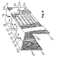
- the hinge pin support member 16 as can be seen from Figure 2 of the drawings, comprises two parts 20 which are "L" shaped in cross-section, the leg 20a of each part being disposed at right angles to the leg 20b and extending lengthwise thereof.
- Alternative projections and recesses 22, 24 are provided in the leg 20a of each part 20 and are arranged such that when the two parts are placed together as shown in Figure 2 the projection 22 on one part will engage in the recesses 24 in the other part.
- Each part 20 is formed so that the end portions of the leg 20b are stepped outwardly relative to the central portion whereby when the parts are placed together as previously described, the distance between the inner faces of the end portions of the legs 20b is greater than the distance between the inner faces of the center positions.
- a plurality of nail like projections 26 are formed on the center portion of each part 20 and are directed inwardly of the part into an area bounded by the legs 20a, 20b.
- the projections are formed integrally with the associated part in a manner well known to those skilled in the art of producing gang nails, that is plates which have nail like projections formed thereon which are employed to interconnect or reinforce abutting faces of pieces of timber.
- Two holes 28 are formed in the leg 20b of each part 20, the holes being identically located one at each end of the part adjacent to the end of the leg 20b remote from the leg 20a.
- a tab 30 is provided on one end portion of each part 20 and is disposed between the hole 28 and the central portion.
- the tab 30 is formed integrally with the part 20 by punching out a section of the part 20 having the shape of the tab 30. Thus the tab can be moved to a position where it projects latterally of the leg 20b in the direction of the leg 20a.
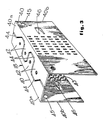
- hinge pin support member 18 is similar in construction to that described with reference to Figure 2 of the drawings.
- the member 18 comprises two parts 40 which are L-shaped in cross-section, the leg 40a being disposed at right angles to the leg 40b and extending lengthwise thereof.
- the leg 40a is shorter than the leg 40b.
- Alternate projections and recesses 42 and 44 are provided in the leg 40a of each part 40, and as in the hinge member 16, the projections and recesses are arranged such that when the parts 40 are placed together as shown in Figure 3 the projections in one part will engage in the recesses in the other part.
- part 40 can be moved transversly relative to each other, but relative parallel movement will be prevented.
- the length the leg 40a of each part 40 is such that when the parts are placed together as previously described the distance between the outer faces of the legs 40b will be less than the distance between the inner faces of the end portions of the member 16.
- a plurality of nail like projections 43 are formed in the central portion of the leg 40a of each member in the manner previously described whilst two holes 45 are formed in each leg 40b. The holes 45 are disposed one at each corner of the leg 40b adjacent to its junction with the associated leg 40a.
- a tab 46 is formed in the leg 40b of each part 40, in the manner previously described and is disposed between the outermost line of nail like projections 43 and the hole 45 at that end of the part 40.
- a part 20 of the hinge member 16 is disposed with the leg 20a uppermost and the leg 20b directed downwardly. Then the tab 30 is bent inwardly of the part so as to project laterally and positioned so as to be located at the right hand end of the part as shown in Figures 1 and 2 with the tab 30 abutting the end face of the beam, and the leg 20a resting on the upper face of the beam 10.
- the part 20 is then secured to beam by embedding the projections 26 in the beam 10.
- the second part 20 is then placed on the beam 10 with its projections 22 engaged in the recesses 24 of the other part 20 and when so located it is secured to the beam by embedding its projections 26 in the beam.
- the holes 28 at the right hand end of the parts will be in axial alignment and spaced beyond the end of the beam 10.
- the hinge member 18 is then mounted on the end of the beam 12. This is effected by positionning one part 40 with its leg 40a horizontal and abutting the underside of the beam 12 and the leg 40b vertical, the tab 46 which is bent inwardly of the part so as to project laterally of the leg 40b and in the same direction as the leg 40a, abutting the end face of the beam.
- the part is then secured to the beam 12 by embedding the projections 43 in the beam.
- the hole 45 in the part 40 is spaced beyond the end of the beam 12.
- the second part 40 is then placed on the beam 12, with its projections 42 engaged in the recesses 44 of the first member whereupon it is secured to the beam by embedding the projections 43 in the beam.
- the beam 12 is then offered up to the beam 10, and the projecting end of the member 18 inserted into the projecting end of the member 16 until the holes 28 and 45 are aligned.
- the pivot pin 14 is then located in the holes and suitably retained therein.
- each hinge pin support it is only necessary to accurately locate one part of each hinge pin support, the second part of each support locating itself relative to the first by means of the interengaging projections and grooves. It will also be seen that by correct selection of the horizontal spacing of the pivot pin holes and the tab when it projects laterally of the leg in which it is formed, will ensure that when the two members 16 and 18 can pivot relative to the other.
- hinge members have been shaped for use with rectangular beams, other shapes can be employed.
- hinge members can be used on beams of varying width. In such a case, it is preferred that the projections and grooves do not become completely disengaged.
- hinge pin supports are used in conjunction with wooden beams
- the hinge can be used in conjunction with natural and man-made materials, which can be penetrated by nail like members.
Landscapes
- Engineering & Computer Science (AREA)
- Architecture (AREA)
- Physics & Mathematics (AREA)
- Electromagnetism (AREA)
- Civil Engineering (AREA)
- Structural Engineering (AREA)
- Joining Of Building Structures In Genera (AREA)
- Hinges (AREA)
Claims (4)
Applications Claiming Priority (2)
| Application Number | Priority Date | Filing Date | Title |
|---|---|---|---|
| CA435978 | 1983-09-02 | ||
| CA000435978A CA1207123A (fr) | 1983-09-02 | 1983-09-02 | Support d'axe de charniere |
Publications (3)
| Publication Number | Publication Date |
|---|---|
| EP0139599A2 EP0139599A2 (fr) | 1985-05-02 |
| EP0139599A3 EP0139599A3 (en) | 1985-11-13 |
| EP0139599B1 true EP0139599B1 (fr) | 1987-11-25 |
Family
ID=4126006
Family Applications (1)
| Application Number | Title | Priority Date | Filing Date |
|---|---|---|---|
| EP84420142A Expired EP0139599B1 (fr) | 1983-09-02 | 1984-08-29 | Moyen de support d'un pivot sur poutres, sous-poutres etc. |
Country Status (5)
| Country | Link |
|---|---|
| US (1) | US4675942A (fr) |
| EP (1) | EP0139599B1 (fr) |
| JP (1) | JPS6145043A (fr) |
| CA (1) | CA1207123A (fr) |
| DE (1) | DE3467788D1 (fr) |
Families Citing this family (4)
| Publication number | Priority date | Publication date | Assignee | Title |
|---|---|---|---|---|
| US5005256A (en) * | 1990-09-28 | 1991-04-09 | Jang Yeong An | Structure of hinge |
| US7703738B2 (en) * | 2005-05-31 | 2010-04-27 | Siemens Industry, Inc. | System and method for assembling a structure |
| US8739726B2 (en) * | 2011-02-15 | 2014-06-03 | Bellingham Marine Industries, Inc. | Dock system including collapsible frame, and method for assembling dock system including collapsible frame |
| JP2015094112A (ja) * | 2013-11-11 | 2015-05-18 | 有限会社ライン工業 | 木材の接合金具及び木材の接合構造 |
Family Cites Families (10)
| Publication number | Priority date | Publication date | Assignee | Title |
|---|---|---|---|---|
| GB593975A (fr) * | ||||
| DE45608C (de) * | E. PRZI-BILLA in Köln, Friesenstr. 38 | Selbsttätiger Tiefbohrapparat für Kurbelbetrieb und Wasserspülung | ||
| FR489417A (fr) * | 1917-08-08 | 1919-02-03 | Louis Dubourg | Charnière renforcée avec joues d'assemblage |
| US2246509A (en) * | 1938-09-06 | 1941-06-24 | Davies Albert Edward | Connecting device |
| US2495962A (en) * | 1947-03-26 | 1950-01-31 | Frank F Gravelle | Hinge |
| US3439378A (en) * | 1966-07-05 | 1969-04-22 | Cole Mfg Co | Hinge |
| US3447198A (en) * | 1966-09-28 | 1969-06-03 | Doerner Products Co Ltd | Chair control back back-plate with integrally formed bearings |
| US3535845A (en) * | 1968-09-20 | 1970-10-27 | Arthur L Troutner | Pitched truss and ridge connector therefor |
| DD117097A1 (fr) * | 1975-01-02 | 1975-12-20 | ||
| US4400847A (en) * | 1981-07-29 | 1983-08-30 | U.S. Solar Corporation | Self-clamping hinge for solar collector frames and the like |
-
1983
- 1983-09-02 CA CA000435978A patent/CA1207123A/fr not_active Expired
-
1984
- 1984-08-15 US US06/640,864 patent/US4675942A/en not_active Expired - Fee Related
- 1984-08-29 DE DE8484420142T patent/DE3467788D1/de not_active Expired
- 1984-08-29 EP EP84420142A patent/EP0139599B1/fr not_active Expired
- 1984-09-03 JP JP59182891A patent/JPS6145043A/ja active Pending
Also Published As
| Publication number | Publication date |
|---|---|
| US4675942A (en) | 1987-06-30 |
| EP0139599A3 (en) | 1985-11-13 |
| JPS6145043A (ja) | 1986-03-04 |
| CA1207123A (fr) | 1986-07-08 |
| DE3467788D1 (en) | 1988-01-07 |
| EP0139599A2 (fr) | 1985-05-02 |
Similar Documents
| Publication | Publication Date | Title |
|---|---|---|
| US5524397A (en) | Framing system for wood frame buildings | |
| US4291996A (en) | Positive nail angling device for metal connectors | |
| US3979874A (en) | Suspended ceiling system and runner joints therefor | |
| US6645033B1 (en) | Building element for a toy building set | |
| CA2188945C (fr) | Moule a beton a panneaux de mousse interconnectes | |
| US4423977A (en) | Single element slope and skew hanger | |
| US5253465A (en) | Multiple framing member connection | |
| US4122647A (en) | Joist bridging member | |
| US4260277A (en) | Bracket for wooden structures | |
| US5620275A (en) | Timber beam hanger and resulting beam connection | |
| GB2222221A (en) | Improvements in or relating to connectors | |
| EP0204281A2 (fr) | Structure porteuse pour un faux plancher surélevé | |
| US4523419A (en) | Ribbed connector and joist structure | |
| US4894963A (en) | Building kit | |
| US4562683A (en) | Hinged metal webs for truss structures | |
| US4890953A (en) | Wood beam joint and method of forming | |
| US4483120A (en) | Hinged metal web for truss structures and method of making | |
| US5220766A (en) | Skewed beam hanger | |
| EP0139599A2 (fr) | Moyen de support d'un pivot sur poutres, sous-poutres etc. | |
| US2751644A (en) | Joist hanger | |
| EP0248017B1 (fr) | Poutre et procede de production | |
| JPH0526173Y2 (fr) | ||
| EP1026336B1 (fr) | Interconnexion de fermes de toit | |
| GB2027477A (en) | Joist hanger | |
| JPH065444Y2 (ja) | 壁下地材用スタッド |
Legal Events
| Date | Code | Title | Description |
|---|---|---|---|
| PUAI | Public reference made under article 153(3) epc to a published international application that has entered the european phase |
Free format text: ORIGINAL CODE: 0009012 |
|
| AK | Designated contracting states |
Designated state(s): AT BE CH DE FR GB IT LI LU NL SE |
|
| PUAL | Search report despatched |
Free format text: ORIGINAL CODE: 0009013 |
|
| AK | Designated contracting states |
Designated state(s): AT BE CH DE FR GB IT LI LU NL SE |
|
| 17P | Request for examination filed |
Effective date: 19851023 |
|
| 17Q | First examination report despatched |
Effective date: 19860710 |
|
| RBV | Designated contracting states (corrected) |
Designated state(s): CH DE FR LI |
|
| GRAA | (expected) grant |
Free format text: ORIGINAL CODE: 0009210 |
|
| AK | Designated contracting states |
Kind code of ref document: B1 Designated state(s): CH DE FR LI |
|
| REF | Corresponds to: |
Ref document number: 3467788 Country of ref document: DE Date of ref document: 19880107 |
|
| ET | Fr: translation filed | ||
| PLBE | No opposition filed within time limit |
Free format text: ORIGINAL CODE: 0009261 |
|
| STAA | Information on the status of an ep patent application or granted ep patent |
Free format text: STATUS: NO OPPOSITION FILED WITHIN TIME LIMIT |
|
| 26N | No opposition filed | ||
| PG25 | Lapsed in a contracting state [announced via postgrant information from national office to epo] |
Ref country code: LI Effective date: 19890831 Ref country code: CH Effective date: 19890831 |
|
| PG25 | Lapsed in a contracting state [announced via postgrant information from national office to epo] |
Ref country code: FR Effective date: 19900427 |
|
| REG | Reference to a national code |
Ref country code: CH Ref legal event code: PL |
|
| PG25 | Lapsed in a contracting state [announced via postgrant information from national office to epo] |
Ref country code: DE Effective date: 19900501 |
|
| REG | Reference to a national code |
Ref country code: FR Ref legal event code: ST |