EP0139819A2 - Support pour une perceuse à main - Google Patents
Support pour une perceuse à main Download PDFInfo
- Publication number
- EP0139819A2 EP0139819A2 EP84104147A EP84104147A EP0139819A2 EP 0139819 A2 EP0139819 A2 EP 0139819A2 EP 84104147 A EP84104147 A EP 84104147A EP 84104147 A EP84104147 A EP 84104147A EP 0139819 A2 EP0139819 A2 EP 0139819A2
- Authority
- EP
- European Patent Office
- Prior art keywords
- column
- work stand
- bearing
- base plate
- stand according
- Prior art date
- Legal status (The legal status is an assumption and is not a legal conclusion. Google has not performed a legal analysis and makes no representation as to the accuracy of the status listed.)
- Withdrawn
Links
Images


Classifications
-
- B—PERFORMING OPERATIONS; TRANSPORTING
- B23—MACHINE TOOLS; METAL-WORKING NOT OTHERWISE PROVIDED FOR
- B23Q—DETAILS, COMPONENTS, OR ACCESSORIES FOR MACHINE TOOLS, e.g. ARRANGEMENTS FOR COPYING OR CONTROLLING; MACHINE TOOLS IN GENERAL CHARACTERISED BY THE CONSTRUCTION OF PARTICULAR DETAILS OR COMPONENTS; COMBINATIONS OR ASSOCIATIONS OF METAL-WORKING MACHINES, NOT DIRECTED TO A PARTICULAR RESULT
- B23Q1/00—Members which are comprised in the general build-up of a form of machine, particularly relatively large fixed members
- B23Q1/25—Movable or adjustable work or tool supports
- B23Q1/44—Movable or adjustable work or tool supports using particular mechanisms
- B23Q1/48—Movable or adjustable work or tool supports using particular mechanisms with sliding pairs and rotating pairs
-
- B—PERFORMING OPERATIONS; TRANSPORTING
- B23—MACHINE TOOLS; METAL-WORKING NOT OTHERWISE PROVIDED FOR
- B23Q—DETAILS, COMPONENTS, OR ACCESSORIES FOR MACHINE TOOLS, e.g. ARRANGEMENTS FOR COPYING OR CONTROLLING; MACHINE TOOLS IN GENERAL CHARACTERISED BY THE CONSTRUCTION OF PARTICULAR DETAILS OR COMPONENTS; COMBINATIONS OR ASSOCIATIONS OF METAL-WORKING MACHINES, NOT DIRECTED TO A PARTICULAR RESULT
- B23Q1/00—Members which are comprised in the general build-up of a form of machine, particularly relatively large fixed members
- B23Q1/25—Movable or adjustable work or tool supports
- B23Q1/26—Movable or adjustable work or tool supports characterised by constructional features relating to the co-operation of relatively movable members; Means for preventing relative movement of such members
- B23Q1/28—Means for securing sliding members in any desired position
-
- B—PERFORMING OPERATIONS; TRANSPORTING
- B23—MACHINE TOOLS; METAL-WORKING NOT OTHERWISE PROVIDED FOR
- B23Q—DETAILS, COMPONENTS, OR ACCESSORIES FOR MACHINE TOOLS, e.g. ARRANGEMENTS FOR COPYING OR CONTROLLING; MACHINE TOOLS IN GENERAL CHARACTERISED BY THE CONSTRUCTION OF PARTICULAR DETAILS OR COMPONENTS; COMBINATIONS OR ASSOCIATIONS OF METAL-WORKING MACHINES, NOT DIRECTED TO A PARTICULAR RESULT
- B23Q1/00—Members which are comprised in the general build-up of a form of machine, particularly relatively large fixed members
- B23Q1/25—Movable or adjustable work or tool supports
- B23Q1/44—Movable or adjustable work or tool supports using particular mechanisms
- B23Q1/50—Movable or adjustable work or tool supports using particular mechanisms with rotating pairs only, the rotating pairs being the first two elements of the mechanism
- B23Q1/52—Movable or adjustable work or tool supports using particular mechanisms with rotating pairs only, the rotating pairs being the first two elements of the mechanism a single rotating pair
-
- B—PERFORMING OPERATIONS; TRANSPORTING
- B25—HAND TOOLS; PORTABLE POWER-DRIVEN TOOLS; MANIPULATORS
- B25H—WORKSHOP EQUIPMENT, e.g. FOR MARKING-OUT WORK; STORAGE MEANS FOR WORKSHOPS
- B25H1/00—Work benches; Portable stands or supports for positioning portable tools or work to be operated on thereby
- B25H1/0021—Stands, supports or guiding devices for positioning portable tools or for securing them to the work
- B25H1/0042—Stands
-
- Y—GENERAL TAGGING OF NEW TECHNOLOGICAL DEVELOPMENTS; GENERAL TAGGING OF CROSS-SECTIONAL TECHNOLOGIES SPANNING OVER SEVERAL SECTIONS OF THE IPC; TECHNICAL SUBJECTS COVERED BY FORMER USPC CROSS-REFERENCE ART COLLECTIONS [XRACs] AND DIGESTS
- Y10—TECHNICAL SUBJECTS COVERED BY FORMER USPC
- Y10S—TECHNICAL SUBJECTS COVERED BY FORMER USPC CROSS-REFERENCE ART COLLECTIONS [XRACs] AND DIGESTS
- Y10S408/00—Cutting by use of rotating axially moving tool
- Y10S408/712—Drill press adapted to use portable hand drill
-
- Y—GENERAL TAGGING OF NEW TECHNOLOGICAL DEVELOPMENTS; GENERAL TAGGING OF CROSS-SECTIONAL TECHNOLOGIES SPANNING OVER SEVERAL SECTIONS OF THE IPC; TECHNICAL SUBJECTS COVERED BY FORMER USPC CROSS-REFERENCE ART COLLECTIONS [XRACs] AND DIGESTS
- Y10—TECHNICAL SUBJECTS COVERED BY FORMER USPC
- Y10T—TECHNICAL SUBJECTS COVERED BY FORMER US CLASSIFICATION
- Y10T408/00—Cutting by use of rotating axially moving tool
- Y10T408/55—Cutting by use of rotating axially moving tool with work-engaging structure other than Tool or tool-support
- Y10T408/561—Having tool-opposing, work-engaging surface
- Y10T408/5614—Angularly adjustable surface
- Y10T408/5616—Adjustable about axis that is parallel to tool-axis
-
- Y—GENERAL TAGGING OF NEW TECHNOLOGICAL DEVELOPMENTS; GENERAL TAGGING OF CROSS-SECTIONAL TECHNOLOGIES SPANNING OVER SEVERAL SECTIONS OF THE IPC; TECHNICAL SUBJECTS COVERED BY FORMER USPC CROSS-REFERENCE ART COLLECTIONS [XRACs] AND DIGESTS
- Y10—TECHNICAL SUBJECTS COVERED BY FORMER USPC
- Y10T—TECHNICAL SUBJECTS COVERED BY FORMER US CLASSIFICATION
- Y10T408/00—Cutting by use of rotating axially moving tool
- Y10T408/65—Means to drive tool
- Y10T408/675—Means to drive tool including means to move Tool along tool-axis
- Y10T408/6779—Rack and pinion
-
- Y—GENERAL TAGGING OF NEW TECHNOLOGICAL DEVELOPMENTS; GENERAL TAGGING OF CROSS-SECTIONAL TECHNOLOGIES SPANNING OVER SEVERAL SECTIONS OF THE IPC; TECHNICAL SUBJECTS COVERED BY FORMER USPC CROSS-REFERENCE ART COLLECTIONS [XRACs] AND DIGESTS
- Y10—TECHNICAL SUBJECTS COVERED BY FORMER USPC
- Y10T—TECHNICAL SUBJECTS COVERED BY FORMER US CLASSIFICATION
- Y10T408/00—Cutting by use of rotating axially moving tool
- Y10T408/83—Tool-support with means to move Tool relative to tool-support
- Y10T408/85—Tool-support with means to move Tool relative to tool-support to move radially
- Y10T408/858—Moving means including wedge, screw or cam
- Y10T408/8588—Axially slidable moving-means
- Y10T408/85896—Annular wedge-collar
Definitions
- the invention relates to a work stand for a hand drill with a height-adjustable bearing block on a pillar, a guide plate pivotally mounted on the bearing block about a horizontal axis, a lifting slide displaceable in a prismatic guideway of the guide plate and a machine holder mounted pivotably on the lifting slide about a horizontal axis.
- a pivoting device in which a central pin or the like is comprised of two half cylinder shells which can be pressed together by screws and thus clamped onto the pin .
- a continuous pivoting movement up to a full rotation is possible.
- the half-cylinder shells must have a relatively large length, which would lead to an excessive size in the case of a work stand with two horizontal pivot axes.
- the invention has for its object to provide a generic work stand that is infinitely adjustable up to a full rotation about both axes of rotation, which can accommodate large torques in the determined state, which has a small size and is easy to manufacture.
- the guide plate and the machine holder are each mounted with a truncated cone-shaped, widening towards the outside in associated conical pivot bearings on the bearing block or lifting slide.
- Such one conical rotary guide is infinitely adjustable at any angle.
- the decisive advantage is that the wedge action of the conical bearing surfaces allows high clamping moments to be achieved even with a small overall length.
- the conical bearing guide ensures that the axis of rotation is centered, so that no additional centering devices such as guide webs or the like need be provided. The two swivel devices can therefore be produced with a comparatively low production cost.
- the bearing block and the lifting slide can each consist of two housing parts which are divided parallel to their direction of displacement and to the axis of the conical pivot bearing and each clamped together by enclosing one of the bearing pins, each with a half conical shell.
- the bearing block and the lifting slide are constructed from two housing parts, the assembly of the truncated cone-shaped bearing pins, which become wider towards the outside, is completely unproblematic.
- the conical shells of the two housing parts can be operationally tightened or loosened by the one or more tensioning screws which pass closely past the conical shells.
- the clamping forces between the two housing parts can be varied continuously in a convenient manner, ie. H.
- the trunnions can be tightened or loosened. Due to the high clamping torques, short adjustment paths are sufficient to achieve a sufficient tightening of the bearing journals.
- the bearing journal of the machine holder can carry at its free end a coaxial worm wheel, in which an adjusting worm mounted in the lifting slide engages. After releasing the clamping, the machine holder can thus be rotated in a particularly sensitive manner with respect to the lifting slide, and even heavier machines do not need to be pulled out of the machine holder during the adjustment process.
- the frustoconical bearing journal of the guide plate can be screwed to the guide plate by a central axial screw, the actuating end of the screw can be accessed from the side for the purpose of attaching a turning tool or turning handle, and the bearing journal can be operated by operating the screw in the Pivots can be clamped or loosened.
- the bearing journals are not clamped by changing the pivot bearing, but rather by an axial displacement of the bearing journal.
- the base plate has a working surface lying in front of and next to the column, which merge into one another.
- the Base plate should be approximately square and the column should be arranged off-center in a 2: 1 aspect ratio.
- the base plate can also have an angular plan and the column can be arranged on the inner corner.
- the projection distance between the column and the center of the machine holder advantageously corresponds to approximately half the side length of the base plate.
- the base plate has a molded, longitudinally slotted, cylindrical receiving sleeve, within which the column can be rotated during operation and the halves of which are designed as clamping jaws.
- the base plate can be close to the column with one or more receiving holes for Allen keys and with grooves and / or webs for roll-safe storage of drills or the like.
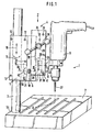
- Fig. 1 shows a work stand 1, which consists of a base plate 2, a column 3 and an adjusting head 4.
- the adjusting head 4 is composed in detail of a bearing block 5, a guide plate 6, a lifting slide 7 and a machine holder 8.
- a hand drill 9 can be clamped.
- the bearing block 5 can be pushed up and down on the column 3 in the vertical direction 10, and can be pivoted about it according to the arrows 11.
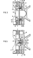
- the determination on the column 3 takes place via the clamping screws 12, which clamp the two housing halves 13, 14 of the bearing block 5 against each other; cf. FIG. 2.
- the guide plate 6 is provided with a truncated cone-shaped bearing pin 15 which widens towards the outside and which is mounted in a pivot bearing 16 on the bearing block 5.
- the bearing pin 15 is screwed to the guide plate 6 with the aid of two screws 17 and nuts 18, the nuts 18 being guided in guide slots 19 and thus prevented from rotating.
- the separate design of guide plate 6 and bearing pin 15 facilitates the manufacture and assembly of these parts.
- the bearing pin 15 in the pivot bearing 16 is fixed by tightening the clamping screws 20 and 21, as a result of which the housing halves 13, 14 and thus the half conical shells 22, 23 are pressed against one another.
- the bearing journal can be determined only by actuating the tensioning screw 21 when selecting suitable manufacturing tolerances.
- the guide plate 6 has a prismatic guide track 25, along which the lifting carriage 7 can be displaced in the direction 26. This movement of the lifting carriage 7 causes the tool 27 to be advanced and can be controlled via a toothed rack 28, a pinion 29 and a control lever 30; compare FIGS. 1 and 2.
- the lifting slide 7 is also made of two halves 31, 32 which can be pressed together by means of clamping screws 33.
- the housing halves 31, 32 each have a half conical shell 34, 35, which together form a rotary bearing 36 for the frustoconical bearing journal 37 of the machine holder 8.
- the bearing pin 37 of the machine holder 8 carries at its free end a coaxial worm wheel 38, into which an adjusting screw 39 mounted in the lifting slide 7 engages.
- the adjustment screw. 39 is in turn via the rotary lever 40 operated.
- the bearing pin 37 is fixed in the pivot bearing 36 by means of the clamping screw 41.
- the machine 9 can be pivoted in a vertical plane in two ways: on the one hand, a rotation around the bearing journal 15 in the direction of the arrows 42 is possible, which results in a change in the feed direction 26. On the other hand, a rotation of the bearing pin 37 according to the arrows 43 causes the machine 9 to pivot relative to the feed direction 26.
- a rotation of the bearing pin 37 according to the arrows 43 causes the machine 9 to pivot relative to the feed direction 26.
- the tool 27 can come into positions, in particular during milling work, which can result in a high moment load on the rotary bearings 16, 36, but which are safely absorbed in the construction according to the invention.
- Fig. 4 shows a work stand 44, the base plate 2, column 3, bearing block 4, lifting carriage 7 and machine holder -8 are identical to the embodiment of FIG. 1. Only the guide plate 45 and the frustoconical bearing journal 46 are new.
- the bearing journal 46 is, as shown in more detail in FIG. 5, by a central axial screw 47 the guide plate 45 screwed. At the actuating end 48 of the screw 47, a nut 49 is placed, which can be actuated via a turning tool or a turning handle 50 indicated by dash-dotted lines.
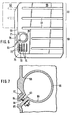
- the base plate 55 of the work stand which is made of cast iron, is provided with an integrally formed receiving sleeve 56 for the column 3, which is arranged off-center at the rear edge 58 of the base plate with a side division ratio of approximately 2: 1.
- the overall approximately square base plate 55 comprises a working surface 59 which extends as usual in front of the column and an additional working surface 60 lying next to it and extending as far as the column, in which, as usual, slots 61 are arranged for attaching workpiece clamping elements or the like.
- the secondary work surface can also extend beyond the rear edge 58 in accordance with a modified embodiment, so that a base plate 62 of an angular plan results, on the inner corner of which the column lies.
- the receiving sleeve 56 for the column is provided with a longitudinal slot 63, the slot edges being provided with angled flanges 64, 65, which can be clamped together by a screw 66 with an Allen head 67, so that the column for operational adjustment between the jaws 68 and 69 of the Sleeve 56 can be tightened or loosened.
- a scale 70 surrounding the receiving opening for the column is provided on the base plate. Furthermore, the base plate in the vicinity of the column is provided with receiving holes 71, 72 for Allen keys and with raised webs 73 and grooves 74 therebetween for the roll-proof storage of drills or the like.
Landscapes
- Engineering & Computer Science (AREA)
- Mechanical Engineering (AREA)
- Drilling And Boring (AREA)
- Machine Tool Units (AREA)
Applications Claiming Priority (2)
| Application Number | Priority Date | Filing Date | Title |
|---|---|---|---|
| DE3339438 | 1983-10-29 | ||
| DE19833339438 DE3339438A1 (de) | 1983-10-29 | 1983-10-29 | Arbeitsstaender fuer eine handbohrmaschine |
Publications (2)
| Publication Number | Publication Date |
|---|---|
| EP0139819A2 true EP0139819A2 (fr) | 1985-05-08 |
| EP0139819A3 EP0139819A3 (fr) | 1986-08-27 |
Family
ID=6213146
Family Applications (1)
| Application Number | Title | Priority Date | Filing Date |
|---|---|---|---|
| EP84104147A Withdrawn EP0139819A3 (fr) | 1983-10-29 | 1984-04-12 | Support pour une perceuse à main |
Country Status (4)
| Country | Link |
|---|---|
| US (1) | US4582105A (fr) |
| EP (1) | EP0139819A3 (fr) |
| JP (1) | JPS6125706A (fr) |
| DE (1) | DE3339438A1 (fr) |
Cited By (7)
| Publication number | Priority date | Publication date | Assignee | Title |
|---|---|---|---|---|
| AU593703B2 (en) * | 1986-11-17 | 1990-02-15 | Keith John Attwood | Telescopic drill stand |
| EP0374550B1 (fr) * | 1988-12-21 | 1994-08-17 | MAHO Aktiengesellschaft | Dispositif additionnel, par exemple pour une fraiseuse |
| GB2321609A (en) * | 1997-02-03 | 1998-08-05 | Bosch Gmbh Robert | Locating aid for a drilling implement |
| EP2463054A1 (fr) * | 2010-12-09 | 2012-06-13 | HILTI Aktiengesellschaft | Dispositif destiné au guidage d'un outil |
| CN102728865A (zh) * | 2012-06-21 | 2012-10-17 | 苏州凯尔博精密机械有限公司 | 一种钻孔装置 |
| CN104816353A (zh) * | 2015-05-06 | 2015-08-05 | 周玉萍 | 一种木结构房屋木材打孔机 |
| CN111775260A (zh) * | 2020-07-24 | 2020-10-16 | 杭州欣伊家具有限公司 | 一种用于家具生产的取孔机构 |
Families Citing this family (24)
| Publication number | Priority date | Publication date | Assignee | Title |
|---|---|---|---|---|
| AT384983B (de) * | 1985-12-17 | 1988-02-10 | Ettinger Alfred | Vorrichtung zum befestigen einer werkzeugmaschine, z.b. handkreissaege |
| US5006022A (en) * | 1989-05-02 | 1991-04-09 | Bernard Miller | Axially movable tool and guide |
| US4932814A (en) * | 1989-07-24 | 1990-06-12 | York Ronald A | Portable line boring machine |
| DE4033370A1 (de) * | 1990-04-17 | 1991-10-24 | Maxion Werkzeuge Maschinen | Bohrstaender fuer eine handbohrmaschine |
| US5639192A (en) * | 1995-07-18 | 1997-06-17 | Chen; Ruey Zon | Means for preventing a drawer from being completely removed from a drill press |
| US5660508A (en) * | 1996-04-15 | 1997-08-26 | Schneider; Robert A. | Portable radial drill press |
| DE19619023A1 (de) * | 1996-05-10 | 1997-11-13 | Bosch Gmbh Robert | Bohreinrichtung |
| DE29611036U1 (de) * | 1996-06-11 | 1996-08-29 | Otto Häfner GmbH & Co KG, 22045 Hamburg | Klemmvorrichtung für Tischbohrmaschinen |
| US5954460A (en) * | 1997-12-08 | 1999-09-21 | Wolfcraft Gmbh | Drill stand |
| US5902077A (en) * | 1998-03-20 | 1999-05-11 | Marking Methods, Inc. | Variable speed universal drilling tapping and reaming machine |
| US6223794B1 (en) * | 2000-02-05 | 2001-05-01 | James Jones | Woodworking station |
| US6902708B1 (en) * | 2000-04-25 | 2005-06-07 | Air Liquide America Corporation | Method and apparatus for making carbon black |
| DE102004033361A1 (de) * | 2004-07-02 | 2006-01-19 | C. & E. Fein Gmbh | Bohrmaschine, insbesondere Kernlochbohrmaschine |
| RU2278005C1 (ru) * | 2004-10-26 | 2006-06-20 | Владимир Иванович Исаев | Электродрель с устройством для повышения точности сверления |
| US7862265B1 (en) | 2006-09-25 | 2011-01-04 | Clark Bruce A | Off-set drill guide assembly and method of drilling holes in a workpiece |
| US20090162158A1 (en) * | 2007-07-24 | 2009-06-25 | Michael Glodowski | Hand Held Portable Drill Leverage Unit |
| DE102010062703A1 (de) * | 2010-12-09 | 2012-06-14 | Hilti Aktiengesellschaft | Vorrichtung zur Führung eines Fahrzeuggerätes |
| CN102126033A (zh) * | 2011-04-01 | 2011-07-20 | 沪东中华造船(集团)有限公司 | 一种舵机基座钻孔的钻削方法 |
| JP2013146815A (ja) * | 2012-01-18 | 2013-08-01 | Ishikame Kogyo:Kk | 作業台 |
| US20130287508A1 (en) | 2012-04-25 | 2013-10-31 | Milwaukee Electric Tool Corporation | Magnetic drill press |
| US9789600B2 (en) * | 2012-10-31 | 2017-10-17 | Husqvarna Ab | Spacer for spacing a tool from a tool stand |
| CN106607965A (zh) * | 2015-10-26 | 2017-05-03 | 安徽港源家居工艺品有限公司 | 一种简单实用的台钻 |
| RU2696259C2 (ru) | 2017-10-23 | 2019-08-01 | Общество С Ограниченной Ответственностью "Сан Системз" | Солюбилизация хлоргексидина основания, антисептическая и дезинфицирующая композиции |
| CN108406340A (zh) * | 2018-01-30 | 2018-08-17 | 河南机电职业学院 | 一种镭射光定位加工机床 |
Family Cites Families (12)
| Publication number | Priority date | Publication date | Assignee | Title |
|---|---|---|---|---|
| BE359890A (fr) * | 1928-04-19 | |||
| US2820377A (en) * | 1954-06-01 | 1958-01-21 | Buck Mfg Co | Portable magnetic drill press |
| US2876663A (en) * | 1956-03-09 | 1959-03-10 | Eugene W Buck | Pneumatic magnetic drill support |
| US3119286A (en) * | 1962-01-12 | 1964-01-28 | Willey G Forman | Portable power tool attachment |
| US3129937A (en) * | 1962-06-20 | 1964-04-21 | Carr Lane Mfg Co | Angularly adjustable locking trunning |
| FR1529636A (fr) * | 1967-02-17 | 1968-06-21 | Gillet Roquigny Ets | Nouveau pivot spécial à double position de blocage |
| DE2110924A1 (de) * | 1971-03-08 | 1972-09-14 | Carl Zenses | Bohrstaender,insbesondere fuer Heimwerker-Kombinationsmaschinen |
| US3923086A (en) * | 1974-02-25 | 1975-12-02 | Jr Daniel M Spohn | Adjustable radial arm apparatus for use with a router or the like |
| US4188142A (en) * | 1977-11-09 | 1980-02-12 | Olsson Hans O | Lockable swivel coupling |
| DE2821132C2 (de) * | 1978-05-13 | 1982-12-30 | Robert 5446 Engeln Wolff | Aufspannvorrichtung für eine Handbohrmaschine |
| DE3040651C2 (de) * | 1980-10-29 | 1983-09-22 | Robert 5446 Engeln Wolff | Arbeitsständer für Bohrmaschinen |
| DE3216799A1 (de) * | 1982-05-05 | 1983-11-10 | Robert 5446 Engeln Wolff | Arbeitsstaender fuer bohrmaschinen |
-
1983
- 1983-10-29 DE DE19833339438 patent/DE3339438A1/de not_active Withdrawn
-
1984
- 1984-04-12 EP EP84104147A patent/EP0139819A3/fr not_active Withdrawn
- 1984-05-17 JP JP9766884A patent/JPS6125706A/ja active Pending
- 1984-07-02 US US06/626,993 patent/US4582105A/en not_active Expired - Fee Related
Cited By (9)
| Publication number | Priority date | Publication date | Assignee | Title |
|---|---|---|---|---|
| AU593703B2 (en) * | 1986-11-17 | 1990-02-15 | Keith John Attwood | Telescopic drill stand |
| EP0374550B1 (fr) * | 1988-12-21 | 1994-08-17 | MAHO Aktiengesellschaft | Dispositif additionnel, par exemple pour une fraiseuse |
| GB2321609A (en) * | 1997-02-03 | 1998-08-05 | Bosch Gmbh Robert | Locating aid for a drilling implement |
| GB2321609B (en) * | 1997-02-03 | 1999-05-12 | Bosch Gmbh Robert | Locating aid for a hand-guided drilling implement |
| EP2463054A1 (fr) * | 2010-12-09 | 2012-06-13 | HILTI Aktiengesellschaft | Dispositif destiné au guidage d'un outil |
| US8813588B2 (en) | 2010-12-09 | 2014-08-26 | Hilti Aktiengesellschaft | Device for guiding a power tool |
| CN102728865A (zh) * | 2012-06-21 | 2012-10-17 | 苏州凯尔博精密机械有限公司 | 一种钻孔装置 |
| CN104816353A (zh) * | 2015-05-06 | 2015-08-05 | 周玉萍 | 一种木结构房屋木材打孔机 |
| CN111775260A (zh) * | 2020-07-24 | 2020-10-16 | 杭州欣伊家具有限公司 | 一种用于家具生产的取孔机构 |
Also Published As
| Publication number | Publication date |
|---|---|
| US4582105A (en) | 1986-04-15 |
| JPS6125706A (ja) | 1986-02-04 |
| DE3339438A1 (de) | 1985-05-09 |
| EP0139819A3 (fr) | 1986-08-27 |
Similar Documents
| Publication | Publication Date | Title |
|---|---|---|
| DE3339438A1 (de) | Arbeitsstaender fuer eine handbohrmaschine | |
| DE10041210C2 (de) | Kreissägemaschine | |
| DE1034505B (de) | Werkzeugmaschine zum Bearbeiten, z. B. zum Schleifen zylindrischer und konischer Bohrungen von insbesondere feststehenden Werkstuecken | |
| EP0467383A1 (fr) | Dispositif d'affûtage | |
| EP0824998B1 (fr) | Outil pour la manutention d'une machine-outil | |
| DE2623825C3 (de) | Rippenwalzwerk zum Bearbeiten von Tabakrippen | |
| EP0517162B1 (fr) | Fraiseuse-aléseuse | |
| DE4207113C2 (de) | Vorrichtung zum Positionieren und Halten von Werkstücken | |
| DE3232689C2 (de) | Vorrichtung zum Schleifen von gerad- und wendelgenuteten Schneidwerkzeugen | |
| DE3348060C2 (de) | Bohrer-Schleifmaschine | |
| DE2328439C3 (de) | Schwenkbarer Werkstück-Aufspanntisch für Werkzeugmaschinen, insbesondere für Universal-Fräsmaschinen | |
| DE2058005A1 (de) | Werkzeugmaschine | |
| DE1247603B (de) | Vorschubeinrichtung fuer Holzbearbeitungs-maschinen | |
| DE1627381B2 (de) | Tragbare vorrichtung zum gewindeschneiden an rohren o.dgl. | |
| EP1198326B1 (fr) | Dispositif de realisation de parties arrondies ou bombees sur des pieces a usiner, en particulier en bois | |
| DE952486C (de) | Universalwerkzeugmaschine | |
| DE19803375C2 (de) | Vorrichtung zum Positionieren des Werkstücks | |
| AT258085B (de) | Vorrichtung zum Aufnehmen und Bewegen eines Werkstückes für die spanabhebende Bearbeitung von Drallnuten | |
| DE3316364A1 (de) | Vorrichtung zum sichern des stoessels einer werkzeugmaschine, insbesondere einer grosspresse | |
| DE1680348C3 (de) | Spannvorrichtung für Fahrzeugräder an einer Anlage z m Montieren und Demontieren von Reifen | |
| DE3410686C2 (fr) | ||
| DE322011C (de) | Maschine zum Schleifen gezahnter Schneidwerkzeuge, insonderheit umlaufender Fraeser | |
| DE3247672A1 (de) | Verstellbarer fasemesserkopf | |
| AT248822B (de) | Radialbohrmaschine | |
| DE923707C (de) | Revolverdrehbank mit waagerecht gelagertem Revolverkopf |
Legal Events
| Date | Code | Title | Description |
|---|---|---|---|
| PUAI | Public reference made under article 153(3) epc to a published international application that has entered the european phase |
Free format text: ORIGINAL CODE: 0009012 |
|
| AK | Designated contracting states |
Designated state(s): AT CH DE FR GB LI NL |
|
| RTI1 | Title (correction) | ||
| PUAL | Search report despatched |
Free format text: ORIGINAL CODE: 0009013 |
|
| AK | Designated contracting states |
Kind code of ref document: A3 Designated state(s): AT CH DE FR GB LI NL |
|
| STAA | Information on the status of an ep patent application or granted ep patent |
Free format text: STATUS: THE APPLICATION IS DEEMED TO BE WITHDRAWN |
|
| 18D | Application deemed to be withdrawn |
Effective date: 19870302 |