EP0139968A2 - Dispositif de nouage - Google Patents
Dispositif de nouage Download PDFInfo
- Publication number
- EP0139968A2 EP0139968A2 EP84109861A EP84109861A EP0139968A2 EP 0139968 A2 EP0139968 A2 EP 0139968A2 EP 84109861 A EP84109861 A EP 84109861A EP 84109861 A EP84109861 A EP 84109861A EP 0139968 A2 EP0139968 A2 EP 0139968A2
- Authority
- EP
- European Patent Office
- Prior art keywords
- beak
- binding
- control
- rotary drive
- hook
- Prior art date
- Legal status (The legal status is an assumption and is not a legal conclusion. Google has not performed a legal analysis and makes no representation as to the accuracy of the status listed.)
- Granted
Links
- 210000003323 beak Anatomy 0.000 claims abstract description 64
- 238000003780 insertion Methods 0.000 claims abstract description 14
- 230000037431 insertion Effects 0.000 claims abstract description 14
- 241000282326 Felis catus Species 0.000 claims description 9
- 230000000875 corresponding effect Effects 0.000 description 4
- 238000004519 manufacturing process Methods 0.000 description 4
- 238000000034 method Methods 0.000 description 4
- 230000015572 biosynthetic process Effects 0.000 description 2
- 239000002184 metal Substances 0.000 description 2
- 241001533104 Tribulus terrestris Species 0.000 description 1
- 230000005540 biological transmission Effects 0.000 description 1
- 230000001276 controlling effect Effects 0.000 description 1
- 238000005520 cutting process Methods 0.000 description 1
- 238000006073 displacement reaction Methods 0.000 description 1
- KJFBVJALEQWJBS-XUXIUFHCSA-N maribavir Chemical compound CC(C)NC1=NC2=CC(Cl)=C(Cl)C=C2N1[C@H]1O[C@@H](CO)[C@H](O)[C@@H]1O KJFBVJALEQWJBS-XUXIUFHCSA-N 0.000 description 1
- 238000004080 punching Methods 0.000 description 1
Images


Classifications
-
- B—PERFORMING OPERATIONS; TRANSPORTING
- B65—CONVEYING; PACKING; STORING; HANDLING THIN OR FILAMENTARY MATERIAL
- B65H—HANDLING THIN OR FILAMENTARY MATERIAL, e.g. SHEETS, WEBS, CABLES
- B65H69/00—Methods of, or devices for, interconnecting successive lengths of material; Knot-tying devices ;Control of the correct working of the interconnecting device
- B65H69/04—Methods of, or devices for, interconnecting successive lengths of material; Knot-tying devices ;Control of the correct working of the interconnecting device by knotting
-
- B—PERFORMING OPERATIONS; TRANSPORTING
- B65—CONVEYING; PACKING; STORING; HANDLING THIN OR FILAMENTARY MATERIAL
- B65H—HANDLING THIN OR FILAMENTARY MATERIAL, e.g. SHEETS, WEBS, CABLES
- B65H2701/00—Handled material; Storage means
- B65H2701/30—Handled filamentary material
- B65H2701/31—Textiles threads or artificial strands of filaments
Definitions
- the invention relates to a device for producing cat head nodes, in particular for creel, with an insertion device for positioning two parallel thread ends on the knotter, which are overlapped by a binding beak with an L-shaped beak hook and are gripped by the beak hook end each time the rotating driven binding beak passes , whose beak hook is provided with a correspondingly L-shaped, movable scissors half, which cooperates at one control end with a link controlling the opening and closing of the binding pin forming a thread clamp, which is adjustable according to the rotational position of the binding beak.
- Bobbin creels have a large number of bobbins which must be re-equipped after the threads of the bobbins have been unwound.
- the so-called cat head knot is primarily used as the knot, which is comparatively simple, but is therefore easy to manufacture and which has usually grown only when the threads are warmed, without opening.
- the knotters used to manufacture it are comparatively simple. They essentially consist of a rotary-powered binding bill, which has the features mentioned at the beginning.
- a fixed backdrop which acts on the control end of the movable scissor half and thereby opens the binding beak.
- the opened, rotationally driven binding beak overlaps the parallel thread ends and cuts them off when the control end leaves the backdrop.
- the thread ends are clamped at the same time.
- the fixed backdrop causes the binding beak to be opened and closed with every complete revolution.
- an additional gripper must be provided to keep the thread ends out of the area of the snapping binding beak when the thread ends are not to be gripped.
- Such a gripper control is complex.
- the link is arranged as a transverse part between two parallel pivot arms, which are pressed by spring force onto a control cam, which lifts the link at the desired time and thus creates the possibility that the control end of the movable scissor half engages can get with the control contour of the backdrop. Since the swivel arms move on a circular path around the swivel axis, the backdrop moves accordingly. As a result, it cant relative to the control end of the movable half of the scissors.
- the invention has for its object to improve a device with the features mentioned so that it can be constructed more easily and works more reliably.
- the backdrop is arranged in a control slide that can only be adjusted in one plane. It is essential for the invention that a pivoting movement of the backdrop is avoided.
- the control slide which is adjustable according to the invention only in one plane, obviously enables a simple degree guidance of the link, so that tilting of the link relative to the binding bill is excluded. As a result, there are no functional uncertainties in the knot caused by tilting of the backdrop.
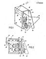
- the control slide is a circular plate with a front plate of a housing for the Rotary drive of the binding beak, which is vertically displaceable in the sliding guide of the housing.
- the use of the front plate for the formation of the backdrop is a significant simplification of the knotter, the vertical displacements occurring only in one plane being reliably controlled by the sliding guides of the front plate.
- the control slide has a cam bolt which interacts with a control cam parallel to the control slide, which is adjusted by the rotary drive.
- the required adjustment of the control slide corresponding to the rotational position of the binding spigot is carried out by the cam pin and the control cam via a positive connection which precludes lifting of the two components from one another as a result of the actuating forces of the binding spigot.
- the necessary assignment between the beak function and control curve is therefore always guaranteed.
- control cam is arranged coaxially with a gear wheel of the rotary drive directly behind the control slide and placed on the gear wheel.
- the rotary drive of the binding bill has an input shaft acted upon by a swivel lever, an axially parallel intermediate shaft driving the control cam relative to the input shaft and an axially parallel binding bill shaft acted upon by the latter.
- the rotary drive can therefore be made comparatively compact while ensuring the required ratio between the input shaft and the binding bill shaft and only requires simple structural and cost-effective parts with which the production outlay can be kept low.
- the side walls of the housing for the rotary drive form the insertion device of the knotter with protruding insertion plates with insertion slots on the front.
- the insertion device can therefore be manufactured as an integral part of the side walls of the housing, which are required anyway, by punching for mass production.
- the thread knot 15 has a housing body 17, the side walls 17 'of which are a front insertion plate 18 and a rear insertion plate 19 with insertion slots as shown in the drawing as insertion means for the thread ends 16 3 form.
- a binding beak 20 essentially consists of a beak hook 21, which is essentially L-shaped and overlaps the thread ends 16 inserted into the insertion device.
- the beak hook 21 is arranged on a binding beak shaft 20 'in a rotationally fixed manner via two pins, which are not designated in any more detail and which allow the beak hook 21 to be adjusted relative to the thread ends 16 located in the insertion device.
- the binding beak 20 from a movable pair of scissors 22, which is the L-shaped corresponding to the beak hook 21.
- the L-shaped beak hook 21 of the binding beak 20 consists, in a manner known per se, of two pieces of sheet metal arranged at a distance from one another, as can be seen for example in FIG. 8. Between the two pieces of sheet metal, the movable scissor half 22 is arranged, which forms a pair of scissors with the beak hook 21, but which at the same time also forms a thread clamp in a conventional manner.
- the binding beak 20 is rotatably mounted with its binding beak shaft 20 'in bearing bushes 31, 32 of the housing body 17 and secured in position with a locking washer 33.
- An intermediate shaft 27 is rotatably mounted in bearing bushes 34, 35 and secured in position with a locking washer 36 parallel to the axis of the binding bill shaft 20 'and to an input shaft 29.
- the input shaft 29 is supported in bearing bushes 37, 38 and carries at its rear end a pivoting lever 30 which sits on the input shaft 29 in a rotationally fixed manner with a pin 39 and, when subjected to a corresponding action by an actuating rod, can rotate the input shaft 29.
- All the gears form a transmission ratio, which accordingly results in a pivoting angle of the pivoting lever 30 of 60 °, for example a rotation of the binding bill shaft 20 'by approximately 850 °.
- control end 22 ' At the end of the movable scissor half 22 there is a control end 22 ', namely essentially a lower A web arranged to the right of the binding bill shaft 20 ', which is arranged with its web ends 22 ", 22""within a circular link 23" of a control slide 23.
- the web ends 22 ", 22"" engage with the link 23', each after which position the control slide 23 assumes relative to the binding bill 20.
- the position of the control slide 23 is determined as a function of the rotational position of the binding beak 20.
- the spool 23 has a cam pin 24 which interacts with a cam 28.
- the control cam 28 is arranged coaxially with the gear 27 ′′ of the rotary drive and is located directly behind the control slide 23 on the gear 27 ′′.
- a rotation of the gearwheel 27 ′′ and thus of the rotary drive causes the control cam 28 to be rotated accordingly.
- the cam contour 28 ′ which projects radially in comparison to the cam contour 28 ′′ of the control cam 28, causes the cam bolt to be driven after a corresponding rotation of the intermediate shaft 27 -Zens 24 and thus a lifting of the control slide 23. This is vertically displaceable in sliding guides 25, 26 of the housing.
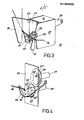
- the thread ends 16 are first driven into the slot of the insert plate 18 and then into the slot of the insert plate 19 from below.
- the slots are shaped so that the thread ends 16 inevitably come behind the L-shaped beak hook 21. If the binding beak 20 is now rotated by pivoting the pivoting lever 30, its beak hook 21 engages behind the thread end 16 according to FIG. 4 and, when the binding beak shaft 20 'is turned further, forms a loop as shown in FIG. 5 after a further half turn. Here, too, it engages behind the thread ends 16.
- the thread loop formed in the process is further rotated during the next half turn of the binding beak until the position shown in FIG. 6 of the binding beak 20 is reached.
- the curve contour 28' comes under the cam bolt 24 and lifts the control slide 23. From then on, the control end 22 'of the movable scissor half 22 no longer has enough space to move without contact within the link 23'. Rather, it touches this link 23 'with the web end 22 "and thereby pushes upwards or swivels the movable scissor half 22 outward, so that the binding beak 20 opens. As a result, the binding beak 20 overlaps the thread ends 16 with the L-shaped beak hook 21 on one side and with the movable scissor half 22 on the other side of the thread ends 16 according to FIG.
- the thread ends 16 on the spool or thread brake side are tightened, so that the thread loop 16 'is tightened, as shown in FIG. 11.
- the thread ends 16 are pulled out of the binding beak 20 or the binding beak 20 opens in that the web end 22 ′′ runs into the area of the opening contour of the link 23 ′. Then the unwinding process can be continued from the creel because a sufficiently tight knot has been created, namely a double cat head knot.
- the knotting device is then reset by swiveling back the pivoting lever 30 so that the binding beak 20 or the binding beak shaft 20 'return to the starting position shown in FIG. 3 and are ready for a new knotting process.
- the knot formation takes place during 2 1/4 turns of the binding beak.
- a double cat head is made.
- the same device to produce single or more than double cat heads, in which the binding bill feed is changed. It must therefore be ensured that the binding bill shaft 20 'only makes half a turn or 2 1/2 turns before the control slide 23 is raised before the binding bill 20 opens to produce a triple cat head. This is easily possible by choosing the starting position of the pivot lever 30.
- the control slide 23 is reset during the return of the binding bill by restoring forces of the movable scissor half 22 after the control cam 28 has released the cam pin 24.
- the advantage of the thread knotter according to the invention is therefore also that it can easily produce single or multiple cat head knots, so that, for example, even threads with at least double cat head knots are knotted and are therefore sufficiently durable.
Landscapes
- Basic Packing Technique (AREA)
- Binders And Loading Units For Sheaves (AREA)
- Sewing Machines And Sewing (AREA)
Applications Claiming Priority (2)
| Application Number | Priority Date | Filing Date | Title |
|---|---|---|---|
| DE19833336509 DE3336509A1 (de) | 1983-10-07 | 1983-10-07 | Vorrichtung zum herstellen von katzenkopfknoten |
| DE3336509 | 1983-10-07 |
Publications (3)
| Publication Number | Publication Date |
|---|---|
| EP0139968A2 true EP0139968A2 (fr) | 1985-05-08 |
| EP0139968A3 EP0139968A3 (en) | 1985-06-05 |
| EP0139968B1 EP0139968B1 (fr) | 1986-10-15 |
Family
ID=6211240
Family Applications (1)
| Application Number | Title | Priority Date | Filing Date |
|---|---|---|---|
| EP84109861A Expired EP0139968B1 (fr) | 1983-10-07 | 1984-08-18 | Dispositif de nouage |
Country Status (5)
| Country | Link |
|---|---|
| US (1) | US4568116A (fr) |
| EP (1) | EP0139968B1 (fr) |
| DE (2) | DE3336509A1 (fr) |
| ES (1) | ES281641Y (fr) |
| IT (2) | IT1182299B (fr) |
Families Citing this family (2)
| Publication number | Priority date | Publication date | Assignee | Title |
|---|---|---|---|---|
| ES2126433B1 (es) * | 1995-05-19 | 1999-12-01 | I Marsans Ricard Borras | Maquina para conformar nudos. |
| KR101736154B1 (ko) * | 2015-07-06 | 2017-05-17 | (주)하이모 | 매듭시스템, 매듭방법 및 그를 이용한 가발 제조방법 |
Family Cites Families (14)
| Publication number | Priority date | Publication date | Assignee | Title |
|---|---|---|---|---|
| US2670230A (en) * | 1951-05-05 | 1954-02-23 | Universal Winding Co | Knotter |
| GB1176186A (en) * | 1966-06-03 | 1970-01-01 | Annodatori Tessili Mesdan | A Yarn Cutting and Securing Device for a Knot-Tying Machine |
| IT1006743B (it) * | 1974-01-04 | 1976-10-20 | Mes Dan Di Messa Pietro | Apparecchio per annodare fili con il nodo cosiddetto da tessitore |
| DE2461328C2 (de) * | 1974-12-24 | 1985-01-31 | Bocon Zofingen AG, Zofingen | Fadenknotvorrichtung |
| DE2539923A1 (de) * | 1975-09-09 | 1977-04-21 | Stueber Kg Otto | Fadenknuepfgeraet |
| CS179229B1 (en) * | 1975-11-12 | 1977-10-31 | Jan Micanek | Equipment for propulsion of nodulated mandrels of knotting device |
| DE2642268A1 (de) * | 1976-09-21 | 1978-03-23 | Strojtex Strojirny Textilniho | Vorrichtung zum verknuepfen von in gegenrichtung laufenden faeden durch einen fischermannknoten |
| IT1063465B (it) * | 1976-11-03 | 1985-02-11 | Mesdan Spa | Annodatore automatico per la formazione del nodo da pescatore particolarmente per filati di grosso titolo |
| DE2655042C2 (de) * | 1976-12-04 | 1986-03-20 | W. Schlafhorst & Co, 4050 Mönchengladbach | Knotvorrichtung |
| DE2741786C2 (de) * | 1977-09-16 | 1983-12-15 | Karl Mayer Textil-Maschinen-Fabrik Gmbh, 6053 Obertshausen | Knoter für Spulmaschinen |
| DE2741785C2 (de) * | 1977-09-16 | 1983-10-20 | Karl Mayer Textil-Maschinen-Fabrik Gmbh, 6053 Obertshausen | Knoter für Spulmaschinen |
| IT7921974U1 (it) * | 1979-06-28 | 1980-12-28 | Mesdan Spa | Gancio per annodatori |
| DD218524A3 (de) * | 1982-10-11 | 1985-02-06 | Fortschritt Veb K | Knuepfvorrichtung fuer ballenpressen |
| DD218985A3 (de) * | 1982-11-22 | 1985-02-20 | Horst Raussendorf | Knuepfer fuer den bindeapparat einer ballenpresse |
-
1983
- 1983-10-07 DE DE19833336509 patent/DE3336509A1/de not_active Withdrawn
-
1984
- 1984-08-18 EP EP84109861A patent/EP0139968B1/fr not_active Expired
- 1984-08-18 DE DE8484109861T patent/DE3460963D1/de not_active Expired
- 1984-09-28 IT IT67968/84A patent/IT1182299B/it active
- 1984-09-28 ES ES1984281641U patent/ES281641Y/es not_active Expired
- 1984-09-28 IT IT8453863U patent/IT8453863V0/it unknown
- 1984-10-09 US US06/658,494 patent/US4568116A/en not_active Expired - Fee Related
Also Published As
| Publication number | Publication date |
|---|---|
| DE3336509A1 (de) | 1985-04-25 |
| IT8467968A0 (it) | 1984-09-28 |
| EP0139968A3 (en) | 1985-06-05 |
| ES281641U (es) | 1985-02-16 |
| EP0139968B1 (fr) | 1986-10-15 |
| ES281641Y (es) | 1985-10-01 |
| IT1182299B (it) | 1987-10-05 |
| US4568116A (en) | 1986-02-04 |
| IT8453863V0 (it) | 1984-09-28 |
| DE3460963D1 (en) | 1986-11-20 |
Similar Documents
| Publication | Publication Date | Title |
|---|---|---|
| DE3007948C2 (de) | Kassette für einen bandförmigen Aufzeichnungsträger | |
| DE68911392T2 (de) | Rundballenpresse. | |
| DE19610818A1 (de) | Vorrichtung zum pneumatischen Verbinden von Faden oder Garn für den Einbau in Textilmaschinen, insbesondere in automatische Spulmaschinen | |
| DE2312512A1 (de) | Vorrichtung zum einsetzen eines bindeelements in die randperforation von loseblaettern | |
| DE2229469B2 (de) | Vorrichtung zur zufuehrung von muenzen zu einer muenzverpackungsmaschine | |
| DE3244887C2 (fr) | ||
| DE2313719C3 (de) | Zusatzvorrichtung für Spulenwickelm aschinen | |
| EP0017753B1 (fr) | Mécanisme d'entraînement et d'inversion du sens de défilement pour ruban encreur | |
| DE2406550B2 (de) | Verfahren und Aufwickelvorrichtung zum Aufbringen von Reservewindungen auf eine Spulenhülse | |
| EP0139968B1 (fr) | Dispositif de nouage | |
| DE2426140C2 (de) | Selbsttätiges Knüpfgerät zur Bildung eines Fischerknotens | |
| DE917479C (de) | Vorrichtung zur Bildung einer Fadenreserve fuer Spulmaschinen | |
| DE2725511A1 (de) | Einrichtung zur verstaerkung eines spulendrahtabschnittes | |
| DE2747556A1 (de) | Automatische garnknuepfvorrichtung zur bildung des netzknotens, besonders fuer garne mit grobem feinheitsgrad | |
| DE3131986A1 (de) | Druckgasspleissvorrichtung fuer textilfaeden | |
| DE1291847B (de) | Vorrichtung zum Zufuehren und Wechseln von Faeden auf einer Doppelzylinder-Rundstrickmaschine | |
| DE1564305C3 (de) | Vorrichtung an einer Wickelmaschine für elektrische Spulen zum Verstärken von Wicklungsanschlüssen aus dünnem Draht | |
| DE263832C (de) | Kötzerspulmaschine | |
| DE2802886B2 (de) | Längs einer Offen-End-Spinnmaschüie verfahrbarer, in einer Halterung eines Wagens angeordneter und mit einem Antrieb versehener Knoter, der eine zusätzliche Querbewegung ausführen kann | |
| DE2752180A1 (de) | Mehrfachdrahtfuehrer fuer spulenwickelmaschinen | |
| DE459520C (de) | Spulmaschine mit einem durch Steigrad gesteuerten Fadenfuehrer | |
| DE396273C (de) | Vorrichtung zum Festlegen der Fadenenden von Stickmaschinenspulen | |
| DE1560369C3 (de) | Vorrichtung zum Einführen der Garnenden in den Knoter auf automatischen Spulmaschinen | |
| DE587042C (de) | Vorrichtung zum selbsttaetigen Umschalten der Farbbandlaengsbewegung an Schreibmaschinen | |
| DE1485396C (de) | Maschine zum Anbringen von Fadenschlaufen an einem Textilmaterial |
Legal Events
| Date | Code | Title | Description |
|---|---|---|---|
| PUAI | Public reference made under article 153(3) epc to a published international application that has entered the european phase |
Free format text: ORIGINAL CODE: 0009012 |
|
| PUAL | Search report despatched |
Free format text: ORIGINAL CODE: 0009013 |
|
| AK | Designated contracting states |
Designated state(s): BE CH DE FR GB LI |
|
| AK | Designated contracting states |
Designated state(s): BE CH DE FR GB LI |
|
| 17P | Request for examination filed |
Effective date: 19850701 |
|
| 17Q | First examination report despatched |
Effective date: 19860123 |
|
| GRAA | (expected) grant |
Free format text: ORIGINAL CODE: 0009210 |
|
| AK | Designated contracting states |
Kind code of ref document: B1 Designated state(s): BE CH DE FR GB LI |
|
| REF | Corresponds to: |
Ref document number: 3460963 Country of ref document: DE Date of ref document: 19861120 |
|
| ET | Fr: translation filed | ||
| PLBE | No opposition filed within time limit |
Free format text: ORIGINAL CODE: 0009261 |
|
| STAA | Information on the status of an ep patent application or granted ep patent |
Free format text: STATUS: NO OPPOSITION FILED WITHIN TIME LIMIT |
|
| 26N | No opposition filed | ||
| PG25 | Lapsed in a contracting state [announced via postgrant information from national office to epo] |
Ref country code: LI Effective date: 19880831 Ref country code: CH Effective date: 19880831 Ref country code: BE Effective date: 19880831 |
|
| BERE | Be: lapsed |
Owner name: HACOBA TEXTILMASCHINEN G.M.B.H. & CO. K.G. Effective date: 19880831 |
|
| PG25 | Lapsed in a contracting state [announced via postgrant information from national office to epo] |
Ref country code: FR Free format text: LAPSE BECAUSE OF NON-PAYMENT OF DUE FEES Effective date: 19890428 |
|
| REG | Reference to a national code |
Ref country code: CH Ref legal event code: PL |
|
| PG25 | Lapsed in a contracting state [announced via postgrant information from national office to epo] |
Ref country code: DE Effective date: 19890503 |
|
| REG | Reference to a national code |
Ref country code: FR Ref legal event code: ST |
|
| PG25 | Lapsed in a contracting state [announced via postgrant information from national office to epo] |
Ref country code: GB Effective date: 19890818 |
|
| GBPC | Gb: european patent ceased through non-payment of renewal fee |