EP0140224A2 - Digitales Signalübertragungssystem - Google Patents
Digitales Signalübertragungssystem Download PDFInfo
- Publication number
- EP0140224A2 EP0140224A2 EP84112068A EP84112068A EP0140224A2 EP 0140224 A2 EP0140224 A2 EP 0140224A2 EP 84112068 A EP84112068 A EP 84112068A EP 84112068 A EP84112068 A EP 84112068A EP 0140224 A2 EP0140224 A2 EP 0140224A2
- Authority
- EP
- European Patent Office
- Prior art keywords
- bit
- bits
- information
- program
- stereo
- Prior art date
- Legal status (The legal status is an assumption and is not a legal conclusion. Google has not performed a legal analysis and makes no representation as to the accuracy of the status listed.)
- Granted
Links
Images


Classifications
-
- H—ELECTRICITY
- H04—ELECTRIC COMMUNICATION TECHNIQUE
- H04J—MULTIPLEX COMMUNICATION
- H04J3/00—Time-division multiplex systems
- H04J3/02—Details
- H04J3/04—Distributors combined with modulators or demodulators
- H04J3/047—Distributors with transistors or integrated circuits
-
- H—ELECTRICITY
- H04—ELECTRIC COMMUNICATION TECHNIQUE
- H04H—BROADCAST COMMUNICATION
- H04H20/00—Arrangements for broadcast or for distribution combined with broadcast
- H04H20/28—Arrangements for simultaneous broadcast of plural pieces of information
- H04H20/30—Arrangements for simultaneous broadcast of plural pieces of information by a single channel
-
- H—ELECTRICITY
- H04—ELECTRIC COMMUNICATION TECHNIQUE
- H04H—BROADCAST COMMUNICATION
- H04H20/00—Arrangements for broadcast or for distribution combined with broadcast
- H04H20/65—Arrangements characterised by transmission systems for broadcast
- H04H20/71—Wireless systems
- H04H20/74—Wireless systems of satellite networks
-
- H—ELECTRICITY
- H04—ELECTRIC COMMUNICATION TECHNIQUE
- H04H—BROADCAST COMMUNICATION
- H04H20/00—Arrangements for broadcast or for distribution combined with broadcast
- H04H20/86—Arrangements characterised by the broadcast information itself
- H04H20/88—Stereophonic broadcast systems
-
- H—ELECTRICITY
- H04—ELECTRIC COMMUNICATION TECHNIQUE
- H04H—BROADCAST COMMUNICATION
- H04H60/00—Arrangements for broadcast applications with a direct linking to broadcast information or broadcast space-time; Broadcast-related systems
- H04H60/09—Arrangements for device control with a direct linkage to broadcast information or to broadcast space-time; Arrangements for control of broadcast-related services
- H04H60/11—Arrangements for counter-measures when a portion of broadcast information is unavailable
-
- H—ELECTRICITY
- H04—ELECTRIC COMMUNICATION TECHNIQUE
- H04H—BROADCAST COMMUNICATION
- H04H60/00—Arrangements for broadcast applications with a direct linking to broadcast information or broadcast space-time; Broadcast-related systems
- H04H60/68—Systems specially adapted for using specific information, e.g. geographical or meteorological information
- H04H60/73—Systems specially adapted for using specific information, e.g. geographical or meteorological information using meta-information
- H04H60/74—Systems specially adapted for using specific information, e.g. geographical or meteorological information using meta-information using programme related information, e.g. title, composer or interpreter
Definitions
- the invention relates to a digital signal transmission system according to the preamble of patent claim 1.
- a digital transmission method is known from "Digital radio via radio satellites, information brochure of the Federal Minister for Research and Technology", page 55 et seq., In which 16 stereo or 32 mono sound broadcast programs are transmitted via satellites.
- the individual channels are PCM-coded, each sample is combined into a modulation frame and then modulated on a 4 PSK carrier.
- Certain bits of the frame are used to transmit transmitter and program type identification information and are combined to form new subframes.
- a “quasi instantaneous value compander” is described in "Rundfunk Technische Mitteilungen", Volume 27, 1983, Issue 1, page 9 ff. For improving the signal quality in digital sound transmission. With such a compander, a certain number of samples with a resolution of e.g. 14 bit coded. A corresponding quantization is then selected as a function of the most significant of the stored code words. Code words with a reduced bit length and a scale factor for the selected quantization range are then transmitted.
- the object of the invention is to achieve sufficient security for the recovery of a scale factor in a known M b modulation frame.
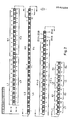
- FIG. 1 shows the structure of a modulation frame according to the invention.
- the same interleaving of the information bits protected by the BCH code is used here, as described in the German patent application P 33 08 025.9.
- the 11th higher-order information bits of a channel which are protected by an error correction system, are replaced by additional bits. These additional bits are adequately protected against transmission errors due to their integration into the error correction system.
- a quasi-instantaneous value companding is used in this modulation frame, in which a total of 13 information bits are transmitted per channel of a stereo program or per monoprogram.
- the letter indicates the left L or right R channel and the number the number of the stereo program.
- the letter Z denotes an additional bit.
- Z2L then means: additional bit of the left channel of the second stereo program.
- the modulation frame length increases by 16 bits. Then 4 bits per channel are transmitted unprotected. To shorten the modulation frame length, however, it is possible to occupy 4 free bits of the special services and the 4 supplementary bits E1-2 to E7-8, so that the modulation frame then has a length of 2 x 328 bits.
- the scale factor serves as additional error protection. If a sample value is defective in the period despite error correction and interpolation and this sample value exceeds the limit specified by the scale factor, then this sample value is either replaced by the preceding sample value or interpolation between the adjacent, correct sample values. In such a case, an unprotected transmission of the scale factor is sufficient.
- the programs are coded with 16 bits and transmitted with 14 bits.
- the scale factor is used to regenerate the 16-bit sample value and must therefore be transmitted with sufficient protection. This is done by integrating the scale factor into a BCH block.
- the scale factor is transmitted 10 times during 1 ms and combined to form a frame as shown in FIG. 3.
- 32 additional bits are transmitted in 1 ms. These are designated in FIG. 3 with Z1 to Z30 for the left channel L of a stereo program, and with Z31-Z60 for the right channel R of a stereo program.
- the last two bits are free.
- a majority vote provides additional protection for the scale factor.
- the most frequently occurring scale factor of a frame according to FIG. 3 is used for the evaluation.
- the scale factor frame is synchronized by synchronizing the transmitter and program type identifier frame. An additional sync word is therefore not required for the scale factor frame. Since the frame for transmitter and program type identification is 320 bits long, every 10th scale factor frame is synchronized.
- this synchronization method When using differential coding of the 4 PSK, which contains clock information in the code, with differential demodulation on the receiver side, this synchronization method provides a sufficiently high level of synchronization security.
- a separate synchronization may be necessary for the scale factor framework.
- the space required for the synchronization word is obtained by transferring fewer scale factors per frame. If 7 scale factors are transmitted per frame, a synchronization word with a length of 11 bits is then obtained.
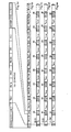
- FIG. 2 shows another exemplary embodiment of a modulation frame according to the invention.
- a flag K is transmitted after the sync word of the main frame.
- the additional bits ZI (1) -ZI (16) are assigned in the modulation frame according to the error correction system F1-2 - F15-16.
- the scale factor frame is created from the additional bits (ZI (1) -ZI (16)), which is synchronized by the sync word of the code bit frame and contains the scale factor protected by a BCH code.
- the number of scale factors contained in the frame is determined by the length of the BCH code used.
- the number of scale factors transmitted per audio channel is then e.g. 3 with a total length of the scale factor frame of 64 bits for a transmission time or scale factor determination phase of 2 m sec. Further program-accompanying information can be transmitted in the remaining bit cells of the frame.
- the program identification frame generated from the characteristic bit K is synchronized by a synchronous word and contains program type information of the transmitted stereo or.
- Monoprograms Two stereo programs, four monoprograms or a combination are combined and separated from the rest by a sync word.
- the synchronization words also serve to synchronize a scale factor frame.
- Fig. 4 shows a section of the subframe for program identification.
- a synchronous word S1 with a length of 16 bits is sent.
- This 16 bit sync word S1 is e.g. a Williard code word. It has the advantage over the 11-bit Barker code word used in the main frame that it has a minimum distance of 2 compared to information in the data part.
- the program identification information PA1, PA1a, PA2, PA2a which are each 8 bits long, are connected to this synchronous word S1. and each represent a mono channel or a pair of stereo channels.
- the data words X1, X2 are free for future applications and are currently with "00000000".
- Synchronous word S2 has a minimum distance of 2 compared to information in the data section.
- 4b shows the complete program identification frame.
- the beginning of a program identification frame is identified by the occurrence of the synchronous word S1. This is followed by the program identification information PA1 / 2 to PA 15/16. Synchronization word S2 is used to separate this program identification information.
- FIGS. 4c to 4e show the scale factor subframes and their temporal assignment to the program identification frame FIG. 4b.
- the first bit of program identification information PA 1/2 to PA 15/16 coincides with the first bit of a scale factor sequence Zi (1) to Zi (16).
- the scale factor frames are synchronized by the synchronization words S1, S2.
- the following code is provided for the program identification information PA1, PA1a ... PA16, PA16a:
- the numbers 0 - 15 under the name “number” indicate the different meanings of the program material. They are binary coded in the first four bits of the eight columns under “Code”. In the fifth column there is an additional coding "M” with regard to music-speech recognition.
- the two bits 2 and 1 are set to "01" to ensure a certain distance from the synchronous words S1, S2.
- the last bit is a parity bit P, by means of which a parity check can be carried out in the receiver in connection with a majority evaluation of the information, which is generally constantly repeated. By a minimum distance of sync words S1. To ensure S2 to the data stream of 2, the parity bit P is set to "0" if the number 7 is even, bit 7 .. bit 1.
- the program identification information is transmitted in the first 8-bit code word PA1 ... PA16 according to the table.
- the second 8-bit code word PA1a ... PA16a contains the stereo identifier, specifically in the form "XXXX" are available for any additional information.
- An evaluation of the information contained in the program identification frame provides an overview of the programs transmitted in a frame. It is therefore possible to search for mono and stereo programs, to find out which types of programs are currently being broadcast and whether music or speech is currently being broadcast. This will evaluate the entire information e.g. simplified by microprocessor system and enables a relatively quick program access or program type search.
Landscapes
- Engineering & Computer Science (AREA)
- Signal Processing (AREA)
- Computer Networks & Wireless Communication (AREA)
- Physics & Mathematics (AREA)
- Astronomy & Astrophysics (AREA)
- General Physics & Mathematics (AREA)
- Microelectronics & Electronic Packaging (AREA)
- Stereo-Broadcasting Methods (AREA)
Abstract
Description
- Die Erfindung betrifft ein digitales Signalübertragungssystem gemäß dem Oberbegriff des Patentanspruchs 1.
- Aus "Digitaler Hörfunk über Rundfunksatelliten, Informationsbroschüre des Bundesministers für Forschung und Technologie", Seite 55 ff., ist ein digitales übertragungsverfahren bekannt, bei dem 16 Stereo- bzw. 32 Mono-Tonrundfunkprogramme über Satelliten übertragen werden. Die einzelnen Kanäle werden PCM-codiert, jeder Abtastwert wird zu einem Modulationsrahmen zusammengefaßt und dann auf einen Träger 4 PSK moduliert.
- Für eine Übertragung von Sender- und Programmart-Kennungsinformation werden bestimmte Bits des Rahmens benutzt und zu neuen Unterrahmen zusammengefaßt.
- Für die Verbesserung der Signalqualität bei digitaler Tonübertragung ist in "Rundfunk Technische Mitteilungen", Jahrgang 27, 1983, Heft 1, Seite 9 ff. ein Quasi-Momentanwert-Kompander beschrieben. Bei einem solchen Kompander werden zunächst eine bestimmte Anzahl von Abtastwerten mit einer Auflösung von z.B. 14 Bit codiert. Sodann wird in Abhängigkeit von höchstwertigen der gespeicherten Codeworte eine entsprechende Quantisierung ausgewählt. Ausgesendet werden dann Codeworte mit e-iner reduzierten Bitlänge sowie ein Skalenfaktor für den ausgewählten Quantisierungsbereich.
- Der Erfindung liegt die Aufgabe zugrunde, bei einem bekannten Mbdula- tionsrahmen eine ausreichende Sicherheit für die Rückgewinnung eines Skalenfaktors zu erreichen.
- Diese Aufgabe wird durch die im Patentanspruch 1 angegebenen Maßnahmen gelöst. Vorteilhafte Weiterbildungen der Erfindung sind in den Unteransprüchen beschrieben.
- Nachstehend wird ein Ausführungsbeispiel anhand der Zeichnung erläutert. Es zeigen:
- Fig. 1 einen erfindungsgemäßen Modulationsrahmen,
- Fig. 2 ein anderes Ausführungsbeispiel,
- Fig. 3 einen Rahmen für den Skalenfaktor,
- Fig. 4a Unterrahmen für Programmkennung (Ausschnitt)
- Fig. 4b Unterrahmen für Programmkennung der Programme 1-16
- Fig. 4c-4e Unterrahmen für Skalenfaktor der einzelnen Programme 1-16.
- Fig. 1 zeigt den Aufbau eines erfindungsgemäßen Modulationsrahmens. Hierbei wird die gleiche Verschachtelung der durch BCH-Code geschützten Informationsbits verwendet, wie sie in der Deutschen Patentanmeldung P 33 08 025.9 beschrieben ist. Im Gegensatz jedoch zum Modulationsrahmen dieser Anmeldung werden die jeweils 11ten höherwertigen Informationsbits eines Kanals, die durch ein Fehlerkorrektursystem geschützt sind, durch Zusatzbits ersetzt. Diese Zusatzbits sind durch ihre Eingliederung in das Fehlerkorrektursystem hinreichend gegenüber Übertragungsfehler geschützt. Bei diesem Modulationsrahmen wird eine Quasimomentanwert-Kompandierung verwendet, bei der insgesamt 13 Informationsbits pro Kanal eines Stereoprogrammes, bzw. pro Monoprogramm übertragen werden. Dabei gibt der Buchstabe den linken L bzw. rechten R Kanal und die Ziffer die Nummer des Stereoprogrammes an. Der Buchstabe Z kennzeichnet ein Zusatzbit. Z2L bedeutet dann: Zusatzbit des linken Kanals des zweiten Stereoprogrammes.
- Der Aufbau je eines Teilrahmens des Modulationsrahmens sieht wie folgt aus:
- Zu Beginn werden 16 Bit für Sonderdienste und Synchronisation übertragen. Die Bit haben folgende Zuordnung:
- 1 Bit Sender- und Programmartkennung, K
- 4 Bit für Sonderdienste
- 11 Bits Synchronisation
- 2 x (10 + 10) Bits geschützte Informationsbits der ungeradzahligen Programme L1-R3 bzw. L5-R7
- 4 x 1 Bit Zusatzbit für Skalenfaktor dieser ungeradzahligen Programme Z1L-Z3R bzw. Z5L-Z7R
- 2 x (10 + 10) Bits geschützte Informationsbits der geradzahligen Programme L2, R4 bzw. L6. R8
- 4 x 1 Bit Zusatzbit für Skalenfaktor dieser geradzahligen Programme Z2L-Z4R bzw. Z6L-Z8R
- 2 x 19 Bits Fehlerkorrektursystem F1-2, F3-4 bzw. F5-6. F7-8
- 2 Bits Ergänzungsbits
- 4 x (3 + 3) Bits ungeschützte Informationsbits der Programme L1-R4 bzw. L5-R8
- Bei linear 14-Bit-Übertragung pro Kanal erhöht sich die Modulationsrahmenlänge um 16 Bit. Es werden dann 4 Bit pro Kanal ungeschützt übertragen. Zur Verkürzung der Modulationsrahmenlänge ist es jedoch möglich, 4 freie Bits der Sonderdienste und die 4 Ergänzungsbits E1-2 bis E7-8 zu belegen, so daß dann der Modulationsrahmen eine Länge von 2 x 328 Bits aufweist.
- Zur Ermittlung der Skalenfaktoren für die einzelnen Programme werden innerhalb eines Zeitrahmens von z.B. 1 ms die Höchstwerte eines jeden Kanals ermittelt. Je nach ermitteltem Höchstwert werden die Skalenfaktoren festgelgt. Bei einer Wortlänge von 3 Bits ergeben sich 8 Skalenfaktor-Bereiche.
- Bei linearer Übertragung dient der Skalenfaktor als zusätzlicher Fehlerschutz. Ist in dem Zeitraum trotz Fehlerkorrektur und Interpolation ein Abtastwert fehlerhaft und überschreitet dieser Abtastwert die durch den Skalenfaktor vorgegebene Begrenzung, so wird dieser Abtastwert entweder durch den vorangehenden Abtastwert ersetzt oder es wird zwischen den benachbarten, richtigen Abtastwerten interpoliert. Für einen solchen Fall ist eine ungeschützte Übertragung des Skalenfaktors ausreichend.
- Treten eine größere Anzahl von Abtastwerten auf, die als fehlerhaft gekennzeichnet sind, dient dies als ein Kriterium für einen gestörten Skalenfaktor. In diesem Fall wird auf eine Ausnutzung des Skalenfaktors für die Fehlerkorrektur verzichtet.
- Bei einer nichtlinearen Übertragung werden die Programme mit 16 Bits codiert und mit 14 Bits übertragen. Der Skalenfaktor dient in diesem Fall zur Regenerierung des 16 Bit-Abtastwertes und muß daher ausreichend geschützt übertragen werden. Dies geschieht durch die Einbindung des Skalenfaktors in einen BCH-Block.
- Während 1 ms wird der Skalenfaktor 10 mal übertragen und zu einem Rahmen, wie er in Fig. 3 dargestellt ist, zusammengefaßt. Bei einer Bitfolgefrequenz von 32 . 103 bit/sek des Hauptrahmens werden in 1 ms 32 Zusatzbits übertragen. Diese sind in Fig 3 mit Z1 bis Z30 für den linken Kanal L eines Stereoprogrammes bezeichnet, und mit Z31-Z60 für den rechten Kanal R eines Steroprogrammes. Die letzten beiden Bits sind jeweils frei. Durch Mehrheitsentscheidung wird ein zusätzlicher Schutz für den Skalenfaktor erzielt. Der am häufigsten auftretende Skalenfaktor eines Rahmens nach Fig. 3 wird zur Auswertung herangezogen.
- Es werden je 3 Bits, z.B. Z1 + Z2 + Z3, zu einem Skalenfaktor 1-10 zusammengefaßt.
- Die Synchronisierung des Rahmens für den Skalenfaktor wird durch die Synchronisierung des Sender- und Programmartkennungs-Rahmens durchgeführt. Ein zusätzliches Synchronwort ist daher für den Skalenfaktorrahmen nicht erforderlich. Da der Rahmen für Sender- und Programmartkennung 320 Bits lang ist, wird jeder 10. Skalenfaktorrahmen synchronisiert.
- Bei Verwendung einer differentiellen Codierung der 4 PSK, die im Code eine Taktinformation beinhaltet, mit empfängerseitiger Differenzdemodulation ist mit diesem Synchronisierungsverfahren eine hinreichend große Synchronisierungssicherheit gegeben.
- Bei Verwendung einer kohärenten Demudolation mit erforderlicher Trägerrückgewinnung ist für den Skalenfaktorrahmen unter Umständen eine eigene Synchronisierung notwendig. Der erforderliche Platz für das Synchronisierungswort wird dadurch erhalten, daß weniger Skalenfaktoren pro Rahmen übertragen werden. Bei Übertragung von 7 Skalenfaktoren pro Rahmen erhält man dann ein Synchronisierungswort mit einer Länge von 11 Bits.
- Fig. 2 zeigt ein anderes Ausführungsbeispiel eines erfindungsgemäßen Modulationsrahmens.
- Bei Einhaltung einer Rahmenlänge von 2 x 320 Bits, wie sie in "Digitaler Hörfunk über Rundfunksatelliten, Informationsbroschüre des Bundesministers für Forschung und Technology", Seite 56, beschrieben ist, sowie einer Übertragung von 14 Bits pro Kanal werden die Sonderdienst- und Ergänzungsbits den Zusatzbits zugeordnet. Ein Kennbit K wird nach dem Synchronwort des Hauptrahmens übertragen. Die Zusatzbits ZI(1)-ZI(16) sind im Modulationsrahmen nach dem Fehlerkorrektursystem F1-2 - F15-16 zugeordnet.
- Der Aufbau je eines Teilrahmens sieht wie folgt aus
- 11 Bits - Synchronisation
- 1 Bit Sender- und Programmartkennung K
- 4 x (11 + 11) Bits geschützte Informationsbits L1-R4, L5-R8
- 2 x 19 Bits Fehlerkorrektursystem F1-2, F3-4 ; F5-6, F7-8
- 4 Bits Zusatzbits ZI(1)-ZI(4) ; ZI(5)-ZI(8)
- 4 x (3 + 3) Bits ungeschützte Informationsbits der Programme L1-R4 ; L5-R8
- Aus den Zusatzbits (ZI(1)-ZI(16)) wird je nach gewähltem Programm (ein ZI-Bit) der Skalenfaktorrahmen erstellt, der durch das Synchronwort des Kennbitrahmens synchronisiert wird und den durch einen BCH-Code geschützten Skalenfaktor enthält. Die Anzahl der im Rahmen enthaltenen Skalenfaktoren wird durch die Länge des verwendeten BCH-Codes bestimmt. Die Anzahl der übertragenen Skalenfaktoren je Tonkanal beträgt dann z.B. 3 bei einer Gesamtlänge des Skalenfaktorrahmens von 64 Bits für eine übertragungszeit bzw. Skalenfaktorermittlungsphase von 2 m sek. In den noch verbleibenden Bitzellen des Rahmens können noch weitere programmbegleitende Informationen übertragen werden.
- Bei einem weiteren Ausführungsbeispiel wird der aus dem Kennbit K erzeugte Programmkennungsrahmen durch ein Synchronwort synchronisiert und enthält Programmartinformationen der übertragenen Stereo-bzw. Monoprogramme. Je zwei Stereo-, vier Monoprogramme oder eine Kombination werden zusammengefaßt und durch ein Synchronwort von dem übrigen getrennt. Die Synchronworte dienen gleichzeitig zur Synchronisierung eines Skalenfaktorrahmens.
- Fig. 4 zeigt einen Ausschnitt aus dem Unterrahmen für Programmkennung. Zu Beginn einer Unterrahmenübertragung wird ein Synchronwort S1 mit 16 Bit Länge gesendet. Dieses 16 Bit Synchronwort S1 ist z.B. ein Williard-Code-Wort. Es hat gegenüber dem im Hauptrahmen verwendeten 11 Bit-Barker-Codewort den Vorteil, daß es gegenüber Informationen im Datenteil eine Mindestdistanz von 2 erreicht. An dieses Synchronwort S1 schließen sich die Programmkennungsinformationen PA1, PA1a, PA2, PA2a an, die jeweils 8 Bit lang sind. und je einen Monokanal bzw. paarweise zusammengefaßt einen Stereokanal repräsentieren. Die Datenworte X1, X2 sind frei für zukünftige Anwendungen und sind z.Zt. mit "00000000" belegt.
- Daran schließt sich ein von dem Synchronwort S1 verschiedenes Synchronwort S2 an. Für dieses Synchronwort S2 wird ein modifizierter 16 Bit Williard-Code verwendet, der sich im -10. und 11. Bit von dem Synchronwort S1 dadurch unterscheidet, daß diese Bits invertiert sind. Das Synchronwort S2 erreicht gegenüber Informationen im Datenteil eine Mindestdistanz von 2.
- Fig. 4b zeigt den vollständigen Programmkennungsrahmen. Der Beginn eines Programmkennungsrahmens wird gekennzeichnet durch das Auftreten des Synchronwortes S1. Daran schließen sich die Programmkennungsinformationen PA1/2 bis PA 15/16 an. Zur Trennung dieser Programmkennungsinformationen wird jeweils das Synchronwort S2 verwendet.
- Fig. 4c bis 4e zeigen die Skalenfaktorunterrahmen, sowie ihre zeitliche Zuordnung zu dem Programmkennungsrahmen Fig. 4b. Wie den Figuren 4c bis 4e zu entnehmen ist, fallen zeitlich jeweils das erste Bit einer Programmkennungsinformation PA 1/2 bis PA 15/16 mit dem ersten Bit einer Skalenfaktorfolge Zi (1) bis Zi (16) zusammen. Die Skalenfaktorrahmen werden durch die Synchronworte S1, S2 synchronisiert.
- Nach einer Zeitperiode tn für die Übertragung des ersten Skalenfaktors Zi (1) bis Zi (16), folgt eine Anzahl Bits 20 für freie Anwendungen. Diese Bits 20 enden zeitlich mit dem letzten Bit der Synchronworte S1, S2. Im Zeitraum tn wird ein Skalenfaktorwert für ein Stereoprogramm bzw. zwei Monoprogramme mehrfach übertragen. In den darauffolgenden Zeitabschnitten tn +1 ... tn +m werden die jeweils für diesen Zeitabschnitt geltenden Skalenfaktoren gesendet.
- Für die Programmkennungsinformation PA1, PA1a ... PA16, PA16a ist folgender Code vorgesehen:

- Für die Stereoübertragung wird im ersten 8-Bit-Codewort PA1 ... PA16 entsprechend Tabelle die Programmkennungsinformation übertragen. Im zweiten 8-Bit-Codewort PA1a ... PA16a ist die Stereokennung enthalten, und zwar in der Formwobei "XXXX" für beliebige Zusatzinformationen zur Verfügung stehen.

- Durch die Auswertung dieser im Programmkennungsrahmen enthaltenen Informationen wird eine Übersicht geliefert über die ein Rahmen übertragenen Programme. Es ist also möglich, nach Mono- und Stereoprogrammen zu suchen, sich zu informieren, welche Arten von Programmen zur Zeit übertragen werden und ob gerade Musik oder Sprache gesendet wird. Damit wird die Auswertung der gesamten Informationen z.B. per Mikroprozessorsystem vereinfacht und ein relativ schneller Programmzugriff bzw. Programmartsuchlauf ermöglicht.
Es folgen bis zur nächsten 16-Bit-Sequenz 2 x 152 Bits für je 4 Stereo-bzw. 8 Monoprogramme mit folgender Zuordnung:
Es folgen bis zur nächsten 12-Bit-Sequenz 2 x 154 Bits für je 4 Stereo-bzw. 8 Monoprogramme mit folgender Zuordnung
Claims (35)
die Bitfolge für die Zusatzinformationen ein Kenn-Bit (K) für Programmartinformation enthält, und daß
die den Programmen zugeordneten Bitwörter Zusatzbit (ZI(1)-ZI(16)) enthalten.
daran anschließend 2 x 154 Bits für je 4 Stereo- bzw. 8 Monoprogramme mit folgender Zuordnung:
Priority Applications (1)
| Application Number | Priority Date | Filing Date | Title |
|---|---|---|---|
| AT84112068T ATE62574T1 (de) | 1983-10-29 | 1984-10-09 | Digitales signaluebertragungssystem. |
Applications Claiming Priority (4)
| Application Number | Priority Date | Filing Date | Title |
|---|---|---|---|
| DE3339382 | 1983-10-29 | ||
| DE19833339382 DE3339382A1 (de) | 1983-10-29 | 1983-10-29 | Digitales signaluebertragungssystem |
| DE3421686 | 1984-06-12 | ||
| DE19843421686 DE3421686A1 (de) | 1984-06-12 | 1984-06-12 | Digitales signaluebertragungssystem |
Publications (3)
| Publication Number | Publication Date |
|---|---|
| EP0140224A2 true EP0140224A2 (de) | 1985-05-08 |
| EP0140224A3 EP0140224A3 (en) | 1988-01-07 |
| EP0140224B1 EP0140224B1 (de) | 1991-04-10 |
Family
ID=25815249
Family Applications (1)
| Application Number | Title | Priority Date | Filing Date |
|---|---|---|---|
| EP84112068A Expired - Lifetime EP0140224B1 (de) | 1983-10-29 | 1984-10-09 | Digitales Signalübertragungssystem |
Country Status (4)
| Country | Link |
|---|---|
| EP (1) | EP0140224B1 (de) |
| DE (1) | DE3484415D1 (de) |
| DK (1) | DK165090C (de) |
| HK (1) | HK5596A (de) |
Cited By (1)
| Publication number | Priority date | Publication date | Assignee | Title |
|---|---|---|---|---|
| EP0238988A3 (en) * | 1986-03-27 | 1989-06-28 | Deutsche Thomson-Brandt Gmbh | Digital signal transmitting system |
Family Cites Families (1)
| Publication number | Priority date | Publication date | Assignee | Title |
|---|---|---|---|---|
| DE3126880A1 (de) * | 1981-07-08 | 1983-01-27 | Licentia Gmbh | Digitales signaluebertragungssystem, insbesondere fuer satelliten-rundfunk |
-
1984
- 1984-10-09 DE DE8484112068T patent/DE3484415D1/de not_active Expired - Lifetime
- 1984-10-09 EP EP84112068A patent/EP0140224B1/de not_active Expired - Lifetime
- 1984-10-26 DK DK512384A patent/DK165090C/da active
-
1996
- 1996-01-11 HK HK5596A patent/HK5596A/xx not_active IP Right Cessation
Cited By (1)
| Publication number | Priority date | Publication date | Assignee | Title |
|---|---|---|---|---|
| EP0238988A3 (en) * | 1986-03-27 | 1989-06-28 | Deutsche Thomson-Brandt Gmbh | Digital signal transmitting system |
Also Published As
| Publication number | Publication date |
|---|---|
| DK512384A (da) | 1985-04-30 |
| DK512384D0 (da) | 1984-10-26 |
| HK5596A (en) | 1996-01-19 |
| EP0140224A3 (en) | 1988-01-07 |
| DK165090C (da) | 1993-02-15 |
| DE3484415D1 (de) | 1991-05-16 |
| DK165090B (da) | 1992-10-05 |
| EP0140224B1 (de) | 1991-04-10 |
Similar Documents
| Publication | Publication Date | Title |
|---|---|---|
| EP0205200B1 (de) | Verfahren zur Übertragung von Audio-Information und Zusatzinformation in digitaler Form | |
| DE69415698T2 (de) | Identifizierung eines Datenstromes der wie eine Paketfolge übertragen wird | |
| EP0127136B1 (de) | Verfahren zur Übertragung von digital codierten Analogsignalen | |
| DE3783194T2 (de) | Verfahren zur rundfunkuebertragung von textnachrichten auf einen untertraeger, verbunden mit einer radiophonen traegerfrequenz. | |
| EP0470988A1 (de) | Verfahren zum übertragen von teletextdaten und einrichtung zur durchführung des verfahrens. | |
| DE3824309A1 (de) | Verfahren zur auswertung von in einem datentelegramm digital codiert empfangener verkehrsnachrichten, sowie rundfunkempfaenger | |
| DE19527187A1 (de) | RDS-TMC-Rundfunkempfänger | |
| DE4430864C2 (de) | Verfahren zum unbemerktem Übertragen und/oder Speichern von Zusatzinformationen innerhalb eines quellencodierten, datenreduzierten Audiosignals | |
| EP1376512A2 (de) | Verfahren zur Informationsübertragung und Informationsempfänger | |
| EP0140224B1 (de) | Digitales Signalübertragungssystem | |
| DE60030932T2 (de) | Suche des optimalen Abtastzeitpunktes in einem TDMA Paketübertragungssystem | |
| DE3339382C2 (de) | ||
| DE4229654A1 (de) | Verfahren zur uebertragung eines audio- und/oder videosignals | |
| EP0238988B1 (de) | Digitales Signalübertragungssystem | |
| EP0118123B1 (de) | Verfahren zur Übertragung und zum Empfang von digitalen Informationssignalen | |
| EP1784934B1 (de) | Verfahren und vorrichtung zur übertragung von zusatzdaten, bezüglich alternativer digitaler sendefrequenzen, in einem analogen rundfunkübertragungssystem | |
| DE19614739A1 (de) | Fehlerrobustes Multiplexverfahren mit HEADER-Kontrollfeld | |
| DE102012210313A1 (de) | Verfahren zum Erkennen, Speichern und/oder Anzeigen eines Sendernamens einesRundfunksenders | |
| DE3421686A1 (de) | Digitales signaluebertragungssystem | |
| EP0836292B1 (de) | Verfahren und Einrichtung zur gebietsabhängigen selektiven Ausgabe von empfangenen digital codierten Meldungen | |
| EP0742668B1 (de) | Verfahren zum Wiedergeben von Datensignalen in Fernseh- oder Hörfunk-Programmkanälen | |
| DE19527185A1 (de) | RDS-TMC-Rundfunkempfänger | |
| DE3937653C2 (de) | ||
| DE4435833A1 (de) | Verfahren zur Codierung, Übertragung, Speicherung und/oder Decodierung eines Informationskanals | |
| DE102013219129B4 (de) | Verfahren zum Empfangen und Anzeigen einer Textinformation |
Legal Events
| Date | Code | Title | Description |
|---|---|---|---|
| PUAI | Public reference made under article 153(3) epc to a published international application that has entered the european phase |
Free format text: ORIGINAL CODE: 0009012 |
|
| AK | Designated contracting states |
Designated state(s): AT BE CH DE FR GB IT LI LU NL SE |
|
| RTI1 | Title (correction) | ||
| PUAL | Search report despatched |
Free format text: ORIGINAL CODE: 0009013 |
|
| AK | Designated contracting states |
Kind code of ref document: A3 Designated state(s): AT BE CH DE FR GB IT LI LU NL SE |
|
| 17P | Request for examination filed |
Effective date: 19880505 |
|
| 17Q | First examination report despatched |
Effective date: 19890719 |
|
| GRAA | (expected) grant |
Free format text: ORIGINAL CODE: 0009210 |
|
| AK | Designated contracting states |
Kind code of ref document: B1 Designated state(s): AT BE CH DE FR GB IT LI LU NL SE |
|
| REF | Corresponds to: |
Ref document number: 62574 Country of ref document: AT Date of ref document: 19910415 Kind code of ref document: T |
|
| ITF | It: translation for a ep patent filed | ||
| REF | Corresponds to: |
Ref document number: 3484415 Country of ref document: DE Date of ref document: 19910516 |
|
| GBT | Gb: translation of ep patent filed (gb section 77(6)(a)/1977) | ||
| ET | Fr: translation filed | ||
| PLBE | No opposition filed within time limit |
Free format text: ORIGINAL CODE: 0009261 |
|
| STAA | Information on the status of an ep patent application or granted ep patent |
Free format text: STATUS: NO OPPOSITION FILED WITHIN TIME LIMIT |
|
| 26N | No opposition filed | ||
| EPTA | Lu: last paid annual fee | ||
| EAL | Se: european patent in force in sweden |
Ref document number: 84112068.6 |
|
| REG | Reference to a national code |
Ref country code: CH Ref legal event code: PFA Free format text: THOMSON CONSUMER ELECTRONIC SALES GMBH |
|
| NLT1 | Nl: modifications of names registered in virtue of documents presented to the patent office pursuant to art. 16 a, paragraph 1 |
Owner name: THOMSON CONSUMER ELECTRONICS SALES GMBH TE HANNOVE |
|
| PGFP | Annual fee paid to national office [announced via postgrant information from national office to epo] |
Ref country code: FR Payment date: 19951018 Year of fee payment: 12 |
|
| PGFP | Annual fee paid to national office [announced via postgrant information from national office to epo] |
Ref country code: GB Payment date: 19960926 Year of fee payment: 13 |
|
| PGFP | Annual fee paid to national office [announced via postgrant information from national office to epo] |
Ref country code: LU Payment date: 19961001 Year of fee payment: 13 |
|
| PGFP | Annual fee paid to national office [announced via postgrant information from national office to epo] |
Ref country code: SE Payment date: 19961018 Year of fee payment: 13 Ref country code: BE Payment date: 19961018 Year of fee payment: 13 Ref country code: AT Payment date: 19961018 Year of fee payment: 13 |
|
| PGFP | Annual fee paid to national office [announced via postgrant information from national office to epo] |
Ref country code: DE Payment date: 19961220 Year of fee payment: 13 |
|
| PG25 | Lapsed in a contracting state [announced via postgrant information from national office to epo] |
Ref country code: FR Effective date: 19970630 |
|
| REG | Reference to a national code |
Ref country code: FR Ref legal event code: ST |
|
| REG | Reference to a national code |
Ref country code: GB Ref legal event code: 746 Effective date: 19970813 |
|
| PG25 | Lapsed in a contracting state [announced via postgrant information from national office to epo] |
Ref country code: LU Free format text: LAPSE BECAUSE OF NON-PAYMENT OF DUE FEES Effective date: 19971009 Ref country code: GB Free format text: LAPSE BECAUSE OF NON-PAYMENT OF DUE FEES Effective date: 19971009 Ref country code: AT Free format text: LAPSE BECAUSE OF NON-PAYMENT OF DUE FEES Effective date: 19971009 |
|
| PG25 | Lapsed in a contracting state [announced via postgrant information from national office to epo] |
Ref country code: SE Free format text: LAPSE BECAUSE OF NON-PAYMENT OF DUE FEES Effective date: 19971010 |
|
| PG25 | Lapsed in a contracting state [announced via postgrant information from national office to epo] |
Ref country code: BE Free format text: LAPSE BECAUSE OF NON-PAYMENT OF DUE FEES Effective date: 19971031 |
|
| BERE | Be: lapsed |
Owner name: THOMSON CONSUMER ELECTRONICS SALES G.M.B.H. Effective date: 19971031 |
|
| GBPC | Gb: european patent ceased through non-payment of renewal fee |
Effective date: 19971009 |
|
| PG25 | Lapsed in a contracting state [announced via postgrant information from national office to epo] |
Ref country code: DE Free format text: LAPSE BECAUSE OF NON-PAYMENT OF DUE FEES Effective date: 19980701 |
|
| EUG | Se: european patent has lapsed |
Ref document number: 84112068.6 |
|
| PGFP | Annual fee paid to national office [announced via postgrant information from national office to epo] |
Ref country code: CH Payment date: 19981027 Year of fee payment: 15 |
|
| PGFP | Annual fee paid to national office [announced via postgrant information from national office to epo] |
Ref country code: NL Payment date: 19981030 Year of fee payment: 15 |
|
| PG25 | Lapsed in a contracting state [announced via postgrant information from national office to epo] |
Ref country code: LI Free format text: LAPSE BECAUSE OF NON-PAYMENT OF DUE FEES Effective date: 19991031 Ref country code: CH Free format text: LAPSE BECAUSE OF NON-PAYMENT OF DUE FEES Effective date: 19991031 |
|
| PG25 | Lapsed in a contracting state [announced via postgrant information from national office to epo] |
Ref country code: NL Free format text: LAPSE BECAUSE OF NON-PAYMENT OF DUE FEES Effective date: 20000501 |
|
| REG | Reference to a national code |
Ref country code: CH Ref legal event code: PL |
|
| NLV4 | Nl: lapsed or anulled due to non-payment of the annual fee |
Effective date: 20000501 |