EP0140228A1 - Steuereinrichtung für Getriebe mit stufenlos veränderbarem Geschwindigkeitsverhältnis - Google Patents
Steuereinrichtung für Getriebe mit stufenlos veränderbarem Geschwindigkeitsverhältnis Download PDFInfo
- Publication number
- EP0140228A1 EP0140228A1 EP84112096A EP84112096A EP0140228A1 EP 0140228 A1 EP0140228 A1 EP 0140228A1 EP 84112096 A EP84112096 A EP 84112096A EP 84112096 A EP84112096 A EP 84112096A EP 0140228 A1 EP0140228 A1 EP 0140228A1
- Authority
- EP
- European Patent Office
- Prior art keywords
- shift actuator
- operating position
- reduction ratio
- continuously variable
- variable transmission
- Prior art date
- Legal status (The legal status is an assumption and is not a legal conclusion. Google has not performed a legal analysis and makes no representation as to the accuracy of the status listed.)
- Granted
Links
- 230000005540 biological transmission Effects 0.000 title claims abstract description 21
- 238000010586 diagram Methods 0.000 description 4
- 239000012530 fluid Substances 0.000 description 3
- 239000000446 fuel Substances 0.000 description 1
- 238000004519 manufacturing process Methods 0.000 description 1
- 238000003908 quality control method Methods 0.000 description 1
Images


Classifications
-
- B—PERFORMING OPERATIONS; TRANSPORTING
- B60—VEHICLES IN GENERAL
- B60W—CONJOINT CONTROL OF VEHICLE SUB-UNITS OF DIFFERENT TYPE OR DIFFERENT FUNCTION; CONTROL SYSTEMS SPECIALLY ADAPTED FOR HYBRID VEHICLES; ROAD VEHICLE DRIVE CONTROL SYSTEMS FOR PURPOSES NOT RELATED TO THE CONTROL OF A PARTICULAR SUB-UNIT
- B60W30/00—Purposes of road vehicle drive control systems not related to the control of a particular sub-unit, e.g. of systems using conjoint control of vehicle sub-units
- B60W30/18—Propelling the vehicle
-
- B—PERFORMING OPERATIONS; TRANSPORTING
- B60—VEHICLES IN GENERAL
- B60W—CONJOINT CONTROL OF VEHICLE SUB-UNITS OF DIFFERENT TYPE OR DIFFERENT FUNCTION; CONTROL SYSTEMS SPECIALLY ADAPTED FOR HYBRID VEHICLES; ROAD VEHICLE DRIVE CONTROL SYSTEMS FOR PURPOSES NOT RELATED TO THE CONTROL OF A PARTICULAR SUB-UNIT
- B60W10/00—Conjoint control of vehicle sub-units of different type or different function
- B60W10/04—Conjoint control of vehicle sub-units of different type or different function including control of propulsion units
-
- B—PERFORMING OPERATIONS; TRANSPORTING
- B60—VEHICLES IN GENERAL
- B60W—CONJOINT CONTROL OF VEHICLE SUB-UNITS OF DIFFERENT TYPE OR DIFFERENT FUNCTION; CONTROL SYSTEMS SPECIALLY ADAPTED FOR HYBRID VEHICLES; ROAD VEHICLE DRIVE CONTROL SYSTEMS FOR PURPOSES NOT RELATED TO THE CONTROL OF A PARTICULAR SUB-UNIT
- B60W10/00—Conjoint control of vehicle sub-units of different type or different function
- B60W10/10—Conjoint control of vehicle sub-units of different type or different function including control of change-speed gearings
- B60W10/101—Infinitely variable gearings
-
- B—PERFORMING OPERATIONS; TRANSPORTING
- B60—VEHICLES IN GENERAL
- B60W—CONJOINT CONTROL OF VEHICLE SUB-UNITS OF DIFFERENT TYPE OR DIFFERENT FUNCTION; CONTROL SYSTEMS SPECIALLY ADAPTED FOR HYBRID VEHICLES; ROAD VEHICLE DRIVE CONTROL SYSTEMS FOR PURPOSES NOT RELATED TO THE CONTROL OF A PARTICULAR SUB-UNIT
- B60W30/00—Purposes of road vehicle drive control systems not related to the control of a particular sub-unit, e.g. of systems using conjoint control of vehicle sub-units
- B60W30/18—Propelling the vehicle
- B60W30/1819—Propulsion control with control means using analogue circuits, relays or mechanical links
-
- F—MECHANICAL ENGINEERING; LIGHTING; HEATING; WEAPONS; BLASTING
- F16—ENGINEERING ELEMENTS AND UNITS; GENERAL MEASURES FOR PRODUCING AND MAINTAINING EFFECTIVE FUNCTIONING OF MACHINES OR INSTALLATIONS; THERMAL INSULATION IN GENERAL
- F16H—GEARING
- F16H61/00—Control functions within control units of change-speed- or reversing-gearings for conveying rotary motion ; Control of exclusively fluid gearing, friction gearing, gearings with endless flexible members or other particular types of gearing
- F16H61/66—Control functions within control units of change-speed- or reversing-gearings for conveying rotary motion ; Control of exclusively fluid gearing, friction gearing, gearings with endless flexible members or other particular types of gearing specially adapted for continuously variable gearings
- F16H61/662—Control functions within control units of change-speed- or reversing-gearings for conveying rotary motion ; Control of exclusively fluid gearing, friction gearing, gearings with endless flexible members or other particular types of gearing specially adapted for continuously variable gearings with endless flexible members
- F16H61/66254—Control functions within control units of change-speed- or reversing-gearings for conveying rotary motion ; Control of exclusively fluid gearing, friction gearing, gearings with endless flexible members or other particular types of gearing specially adapted for continuously variable gearings with endless flexible members controlling of shifting being influenced by a signal derived from the engine and the main coupling
Definitions
- the present invention relates to a control device for a continuously variable transmission.
- This control device comprises a means 12 for determining target reduction ratio based on various kinds of signals 10 representative of operating state of a vehicle, a feedback control means 14 for generating a shift command signal carrying instructions to establish the target reduction ratio determined by the means 12 for determining target reduction ratio, a shift actuator 16 operable on the shift command signal, a continuously variable transmission 18 where a reduction ratio is controlled in response to actuation of the shift actuator 16, and a means 20 for detecting actual reduction ratio in the continuously variable transmission 18.
- the feedback control means 14 is constructed as follows.
- a difference between the target reduction ratio generated by the means 12 for determining target reduction ratio and the actual reduction ratio generated by the means 20 for detecting actual reduction ratio is obtained by an arithmetic unit 14a, this difference is integrated at an integrator 14b and then this integrated value is multiplied with a predetermined integral control gain K1 at a multiplier 14c. On the other hand, this difference obtained at the arithmetic unit 14a is multiplied with a predetermined proportional control gain K2 at a multiplier 14d. The values obtained at the multipliers 14c and 14d are added to each other at an adder 14e and the result is output to the shift actuator 16.
- a reduction ratio vs. operating position of a shift actuator characteristic exibits a non-linear relationship as shown in Fig. 2.
- a relationship of a reduction ratio with a pulley bias force i.e., a hydraulic fluid pressure creating a pulley bias force
- a pulley bias force i.e., a hydraulic fluid pressure creating a pulley bias force
- An object of the present invention is to provide a control device for a continuously variable transmission wherein over the whole operating range of a shift actuator, a consistent feedback control is carried out.
- a control device for a continuously variable transmission performs a feedback control of a shift actuator wherein a control gain of the feedback control is varied depending upon an operating position assumed by the shift actuator.
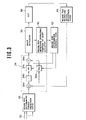
- Fig. 3 shows a first embodiment according to the present invention.
- Various kinds of signals 30 representative of an operating state of a vehicle are fed to a means 32 f.or determining target reduction ratio where, based on these various kinds of signals 30, a target reduction ratio is determined.
- the target reduction ratio is determined based on a predetermined shift pattern, which shift pattern represent is reduction ratios to be established in a continuously variable transmission which always causes an engine to operate on a minimum fuel consumption curve.
- the signal indicating the target reduction ratio given by the means 12 for determining target reduction ratio is fed to a feedback control means 34.
- the feedback control means 34 feeds to a shift actuator 36 a shift command signal which contains instructions to accomplish the target reduction ratio.
- the shift actuator 36 operates on the shift command signal, and a reduction ratio in the continuosly variable transmission 38 is decided depending upon an operating position of the shift actuator 36.
- the operating position assumed by the shift actuator 36 is detected by a means 40 for detecting operating position of shift actuator, and the detected signal is fed to a means 42 for determining control gain.
- the means 42 for determining control gain decides control gains depending upon the operating position assumed by the shift actuator 36, and feeds the result to the feedback control means 34.
- An actual reduction ratio in the continuously variable transmission 38 is detected by a means 44 for detecting actual reduction ratio and feeds the detected result to the feedback control means 34.
- the feedback control means 34 performs the following operation.
- an arithmetic unit 34a a computation is made to give a difference between the target reduction ratio from the means 32 for determining target reduction ratio and the actual reduction ratio from the means 44 for detecting actual reduction ratio.
- This difference is integrated by an integrator 34b and the integrated value is amplified with an integrator control gain Ki at a multiplier 34c.
- a value for Ki is determined by the means 42 for determining control gain.
- the difference obtained by the arithmetic operation at the arithmetic unit 34a is multipled with a proportional gain Kp at another multiplier 34d.
- Kp proportional gain
- a value for Kp is determined by the means 42 for determining control gain.
- the results obtained by the multipliers 34c and 34d are added to each other at an adder 34e, and the combined result is fed to the shift actuator 36.
- the means 42 for determining control gain decides the integral control gain Ki and the proportional control gain Kp in the following manner. As shown in Fig. 2, the relationship between the operating position of the shift actuator 36 and the reduction ratio exibits a non-linear relationship. Let this relationship be expressed by the following equation
- the microcomputer comprises CPU 50, ROM 52, RAM 54 and I/0 56 in the usual manner.
- the ROM 50 stores a control program as shown in Fig. 6.
- step 60 various kinds of signals 30 representative of an operating state of a vehicle are read in (in step 60), a decision is made whether a manual selector lever (not shown) is placed in D-range position or L-range position (in step 62). If L-range is selected, the control proceeds to a step 64 where a table of target reduction ratios for L-range is looked up to determine a target reduction ratio for the operating state of the vehicle, and then the control proceeds to a step 68. If the D-range is selected in step 62, a table of target reduction ratios for D-range is looked up to determine a target reduction ratio for the operating state of the vehicle in step 66 and then the control proceeds to the step 68.
- step 68 an actual reduction ratio is read in from a means 44 for detecting actual reduction ratio.
- step 70 the target reduction ratio is subtracted by the actual reduction ratio to determine a deviation.
- the control proceeds to a step 72 where an operating position of a shift actuator 36 is read in from a means 40 for detecting operating position of shift actuator.
- step 74 the deviation obtained in step 70 is integrated.
- step 76 a correction coeffecient F(x) is given by differentiating f(x), where x is the actual reduction ratio obtained in step 68.
- the function f(x) used is one shown in Fig. 2.
- an integral control gain Ki is given by multiplying an inverse of F(x) with a constant L2 in step 78 and then a proportional control gain Kp is given by multiplying an inverse of F(x) with a constant L1 in step 80.
- an output drive signal is computed on the integral and proportional factors in step 82.
- the drive signal is output to the shift actuator 36 in step 84.
- the function f(x) is not simple, it is desired to use a table look-up.
- Fig. 4 shows a second embodiment according to the present invention.
- the present invention has been embodied in a feedback control device where after a target engine revolution speed is determined by a means 32' for determining target engine revolution speed and an actual revolution speed of an engine 46 is detected by a means 44' for detecting actual. _engine revolution speed, they are processed under a feedback control.
- This second embodiment is different from the first embodiment only in that what is controlled is an engine revolution speed, and the remaining portion is substantially the same as the first embodiment in function and operation.
- a microcomputer may be used such that an optimum integral control gain and an optimum proportional gain for each of the operating positions assumed by the shift actuator are stored in terms of a table and these values are read out for the detected operating position of the shift actuator.
- a control gain of a feedback control is varied depending upon each of operating positions assumed by a shift actuator, a consistent feedback control device is provided which is free from hunting or response delay.
Landscapes
- Engineering & Computer Science (AREA)
- Mechanical Engineering (AREA)
- Chemical & Material Sciences (AREA)
- Combustion & Propulsion (AREA)
- Transportation (AREA)
- General Engineering & Computer Science (AREA)
- Automation & Control Theory (AREA)
- Control Of Transmission Device (AREA)
Applications Claiming Priority (2)
| Application Number | Priority Date | Filing Date | Title |
|---|---|---|---|
| JP58193539A JPS6088264A (ja) | 1983-10-18 | 1983-10-18 | 無段変速機の制御装置 |
| JP193539/83 | 1983-10-18 |
Publications (2)
| Publication Number | Publication Date |
|---|---|
| EP0140228A1 true EP0140228A1 (de) | 1985-05-08 |
| EP0140228B1 EP0140228B1 (de) | 1988-05-25 |
Family
ID=16309752
Family Applications (1)
| Application Number | Title | Priority Date | Filing Date |
|---|---|---|---|
| EP84112096A Expired EP0140228B1 (de) | 1983-10-18 | 1984-10-09 | Steuereinrichtung für Getriebe mit stufenlos veränderbarem Geschwindigkeitsverhältnis |
Country Status (4)
| Country | Link |
|---|---|
| US (1) | US4729103A (de) |
| EP (1) | EP0140228B1 (de) |
| JP (1) | JPS6088264A (de) |
| DE (1) | DE3471515D1 (de) |
Cited By (10)
| Publication number | Priority date | Publication date | Assignee | Title |
|---|---|---|---|---|
| DE3516926A1 (de) * | 1984-05-14 | 1985-11-14 | Nissan Motor Co., Ltd., Yokohama, Kanagawa | Steuerungssystem fuer das untersetzungsverhaeltnis eines getriebes mit kontinuierlich veraenderbarem untersetzungsverhaeltnis |
| DE3518589A1 (de) * | 1984-05-23 | 1985-11-28 | Nissan Motor Co., Ltd., Yokohama, Kanagawa | Regelsystem fuer einen ein getriebe mit stufenlos aenderbarem untersetzungsverhaeltnis enthaltenden antrieb |
| US4829433A (en) * | 1985-10-07 | 1989-05-09 | Nissan Motor Co., Ltd. | Control system for continuously variable transmission |
| US4853857A (en) * | 1986-07-01 | 1989-08-01 | Nissan Motor Company, Ltd. | Ratio control for continuously variable transmission |
| EP0281947A3 (en) * | 1987-03-13 | 1989-12-06 | Borg-Warner Automotive, Inc. | Temperature compensation technique for a continuously vatemperature compensation technique for a continuously variable transmission control system riable transmission control system |
| EP0433929A3 (en) * | 1989-12-18 | 1993-04-07 | Mazda Motor Corporation | Speed shift control system of a continuous transmission |
| WO1997031201A1 (de) * | 1996-02-21 | 1997-08-28 | Zf Friedrichshafen Ag | Regelkreis zur differenzdrehzahl-regelung |
| WO1997031200A1 (de) * | 1996-02-21 | 1997-08-28 | Zf Friedrichshafen Ag | Regelsystem für ein cvt |
| EP1780447A3 (de) * | 2005-10-31 | 2010-06-23 | JATCO Ltd | Steuergerät für stufenloses Fahrzeuggetriebe |
| US8133140B2 (en) | 2005-10-31 | 2012-03-13 | Jatco Ltd | Control apparatus for continuously-variable transmission of vehicle |
Families Citing this family (21)
| Publication number | Priority date | Publication date | Assignee | Title |
|---|---|---|---|---|
| JPH0712810B2 (ja) * | 1985-05-28 | 1995-02-15 | トヨタ自動車株式会社 | 車両用無段変速機の速度比制御装置 |
| US4853858A (en) * | 1986-02-13 | 1989-08-01 | Nissan Motor Co., Ltd. | Control for continuously variable transmission |
| JPH0749824B2 (ja) * | 1986-03-06 | 1995-05-31 | 本田技研工業株式会社 | 車両用無段変速機の変速制御方法 |
| US4821190A (en) * | 1986-05-27 | 1989-04-11 | Ford Motor Company | Closed loop computer control for an automatic transmission |
| JPH086797B2 (ja) * | 1986-07-15 | 1996-01-29 | 本田技研工業株式会社 | 車両用無段変速機の変速制御方法 |
| US5166877A (en) * | 1987-10-02 | 1992-11-24 | Honda Giken Kogyo Kabushiki Kaisha | Method of speed reduction ratio control in continuously variable speed transmission |
| EP0321622A1 (de) * | 1987-12-23 | 1989-06-28 | Honda Giken Kogyo Kabushiki Kaisha | Steuereinrichtung für ein stufenlos regelbares Fahrzeuggetriebe |
| JP2692254B2 (ja) * | 1989-04-21 | 1997-12-17 | 日産自動車株式会社 | 無段変速機の変速制御装置 |
| JP2687576B2 (ja) * | 1989-05-02 | 1997-12-08 | 日産自動車株式会社 | 無段変速機の変速制御装置 |
| JP2561154B2 (ja) * | 1989-08-10 | 1996-12-04 | 本田技研工業株式会社 | 車両用無段変速機の変速制御方法および変速制御装置 |
| JP2844363B2 (ja) * | 1989-09-30 | 1999-01-06 | スズキ株式会社 | 連続可変変速機制御方法 |
| US5062050A (en) * | 1989-10-17 | 1991-10-29 | Borg-Warner Automotive, Inc. | Continuously variable transmission line pressure control |
| EP1059473B1 (de) * | 1995-02-28 | 2002-09-11 | Isuzu Motors Limited | Stufenloses Toroidgetriebe |
| US6142908A (en) * | 1998-07-01 | 2000-11-07 | Nissan Motor Co., Ltd. | Speed ratio controller and control method of continuously variable transmission |
| KR100541912B1 (ko) * | 2002-09-05 | 2006-01-10 | 쟈트코 가부시키가이샤 | V 벨트식 무단 변속기 |
| JP4687096B2 (ja) * | 2004-02-10 | 2011-05-25 | トヨタ自動車株式会社 | ベルト式無段変速機の制御装置 |
| JP4649907B2 (ja) * | 2004-08-05 | 2011-03-16 | 株式会社豊田中央研究所 | 無段変速機の制御装置 |
| JP5707664B2 (ja) * | 2008-09-19 | 2015-04-30 | いすゞ自動車株式会社 | クラッチ制御装置の流量制御弁 |
| JP5235811B2 (ja) * | 2009-07-31 | 2013-07-10 | ダイハツ工業株式会社 | 車両用無段変速機の変速制御装置 |
| JP6543884B2 (ja) * | 2014-01-27 | 2019-07-17 | セイコーエプソン株式会社 | アクチュエーター制御装置、光学モジュール、電子機器、及びアクチュエーター制御方法 |
| WO2017027472A1 (en) * | 2015-08-10 | 2017-02-16 | Dana Limited | System and method of determining an actuator position offset from an infinintely variable transmission output speed |
Citations (5)
| Publication number | Priority date | Publication date | Assignee | Title |
|---|---|---|---|---|
| US3458821A (en) * | 1966-07-05 | 1969-07-29 | Ibm | Variable gain controller |
| FR2314529A1 (fr) * | 1975-06-11 | 1977-01-07 | United Technologies Corp | Systeme de commande adaptable utilisant une retroaction de position |
| FR2385902A1 (fr) * | 1977-03-31 | 1978-10-27 | Renault | Procede de regulation d'un groupe moto-propulseur et dispositif permettant sa mise en oeuvre |
| EP0061735A2 (de) * | 1981-03-28 | 1982-10-06 | Nissan Motor Co., Ltd. | Steuerungssystem für stufenlos regelbare Riemengetriebe |
| EP0101151A1 (de) * | 1982-08-06 | 1984-02-22 | General Motors Corporation | Steuersystem für Getriebe mit stufenlos veränderbarem Geschwindigkeitsverhältnis |
Family Cites Families (5)
| Publication number | Priority date | Publication date | Assignee | Title |
|---|---|---|---|---|
| US4174641A (en) * | 1974-11-20 | 1979-11-20 | Electromatic Drive Corporation | Power drive transmission assembly |
| JPS5944537B2 (ja) * | 1977-08-24 | 1984-10-30 | アイシン精機株式会社 | 自動車の無段変速機の速度比自動制御装置 |
| US4458318A (en) * | 1981-04-24 | 1984-07-03 | Borg-Warner Corporation | Control arrangement for a variable pulley transmission |
| EP0073475B1 (de) * | 1981-08-27 | 1988-02-03 | Nissan Motor Co., Ltd. | Vorrichtung und Verfahren zum Steuern eines Motors und eines stufenlos regelbares Wechselgetriebes |
| JPS58200842A (ja) * | 1982-05-14 | 1983-11-22 | Nissan Motor Co Ltd | Vベルト式無段変速機の制御装置 |
-
1983
- 1983-10-18 JP JP58193539A patent/JPS6088264A/ja active Granted
-
1984
- 1984-10-09 DE DE8484112096T patent/DE3471515D1/de not_active Expired
- 1984-10-09 EP EP84112096A patent/EP0140228B1/de not_active Expired
- 1984-10-11 US US06/659,699 patent/US4729103A/en not_active Expired - Lifetime
Patent Citations (5)
| Publication number | Priority date | Publication date | Assignee | Title |
|---|---|---|---|---|
| US3458821A (en) * | 1966-07-05 | 1969-07-29 | Ibm | Variable gain controller |
| FR2314529A1 (fr) * | 1975-06-11 | 1977-01-07 | United Technologies Corp | Systeme de commande adaptable utilisant une retroaction de position |
| FR2385902A1 (fr) * | 1977-03-31 | 1978-10-27 | Renault | Procede de regulation d'un groupe moto-propulseur et dispositif permettant sa mise en oeuvre |
| EP0061735A2 (de) * | 1981-03-28 | 1982-10-06 | Nissan Motor Co., Ltd. | Steuerungssystem für stufenlos regelbare Riemengetriebe |
| EP0101151A1 (de) * | 1982-08-06 | 1984-02-22 | General Motors Corporation | Steuersystem für Getriebe mit stufenlos veränderbarem Geschwindigkeitsverhältnis |
Cited By (14)
| Publication number | Priority date | Publication date | Assignee | Title |
|---|---|---|---|---|
| DE3516926A1 (de) * | 1984-05-14 | 1985-11-14 | Nissan Motor Co., Ltd., Yokohama, Kanagawa | Steuerungssystem fuer das untersetzungsverhaeltnis eines getriebes mit kontinuierlich veraenderbarem untersetzungsverhaeltnis |
| US4702128A (en) * | 1984-05-14 | 1987-10-27 | Nissan Motor Co., Ltd. | Ratio control system for continuously variable transmission |
| DE3518589A1 (de) * | 1984-05-23 | 1985-11-28 | Nissan Motor Co., Ltd., Yokohama, Kanagawa | Regelsystem fuer einen ein getriebe mit stufenlos aenderbarem untersetzungsverhaeltnis enthaltenden antrieb |
| US4718012A (en) * | 1984-05-23 | 1988-01-05 | Nissan Motor Co., Ltd. | Control system for drive train including continuously variable transmission |
| US4829433A (en) * | 1985-10-07 | 1989-05-09 | Nissan Motor Co., Ltd. | Control system for continuously variable transmission |
| US4853857A (en) * | 1986-07-01 | 1989-08-01 | Nissan Motor Company, Ltd. | Ratio control for continuously variable transmission |
| EP0281947A3 (en) * | 1987-03-13 | 1989-12-06 | Borg-Warner Automotive, Inc. | Temperature compensation technique for a continuously vatemperature compensation technique for a continuously variable transmission control system riable transmission control system |
| EP0433929A3 (en) * | 1989-12-18 | 1993-04-07 | Mazda Motor Corporation | Speed shift control system of a continuous transmission |
| WO1997031201A1 (de) * | 1996-02-21 | 1997-08-28 | Zf Friedrichshafen Ag | Regelkreis zur differenzdrehzahl-regelung |
| WO1997031200A1 (de) * | 1996-02-21 | 1997-08-28 | Zf Friedrichshafen Ag | Regelsystem für ein cvt |
| US5967918A (en) * | 1996-02-21 | 1999-10-19 | Zf Friedrichshafen Ag | Regulating system for a continuously variable transmission (CVT) |
| EP1780447A3 (de) * | 2005-10-31 | 2010-06-23 | JATCO Ltd | Steuergerät für stufenloses Fahrzeuggetriebe |
| US7774120B2 (en) | 2005-10-31 | 2010-08-10 | Jatco Ltd | Control apparatus for continuously-variable transmission of vehicle |
| US8133140B2 (en) | 2005-10-31 | 2012-03-13 | Jatco Ltd | Control apparatus for continuously-variable transmission of vehicle |
Also Published As
| Publication number | Publication date |
|---|---|
| JPS6088264A (ja) | 1985-05-18 |
| DE3471515D1 (en) | 1988-06-30 |
| EP0140228B1 (de) | 1988-05-25 |
| JPH0353508B2 (de) | 1991-08-15 |
| US4729103A (en) | 1988-03-01 |
Similar Documents
| Publication | Publication Date | Title |
|---|---|---|
| EP0140228A1 (de) | Steuereinrichtung für Getriebe mit stufenlos veränderbarem Geschwindigkeitsverhältnis | |
| US4670843A (en) | Control system for continuously variable transmission | |
| US4649486A (en) | Control method for continuously variable transmission or the like | |
| JPH0353509B2 (de) | ||
| GB2159218A (en) | Control system for drive train including continuously variable transmission | |
| KR100512223B1 (ko) | 벨트식 무단 변속기 | |
| US5820514A (en) | Continuously variable transmission controller and control method | |
| EP0127082A2 (de) | Steuerungsvorrichtung für ein stufenloses Kraftfahrzeugmotor-Getriebesystem | |
| US6246940B1 (en) | Speed change controller for automatic transmission | |
| US6067493A (en) | Speed change ratio controller for continuously variable transmission | |
| US5075860A (en) | Continuously variable transmission control system | |
| JPH1151170A (ja) | 無段変速機の変速比制御装置 | |
| EP1059473A3 (de) | Stufenloses Toroidgetriebe | |
| JP3493904B2 (ja) | 無段変速機の変速制御装置 | |
| JP3659094B2 (ja) | 無段変速機の変速制御装置 | |
| JP3446613B2 (ja) | トロイダル型無段変速機の変速制御装置 | |
| KR20040025560A (ko) | V 벨트식 무단 변속기에 있어서의 유압 감소율 제한 장치 | |
| JPS62184937A (ja) | 無段変速機の制御装置 | |
| JP3430934B2 (ja) | Vベルト式無段変速機の変速制御装置 | |
| JP2956419B2 (ja) | 無段変速機の変速制御装置 | |
| JPH0361757A (ja) | 自動変速機の変速ショック軽減装置 | |
| JP3358539B2 (ja) | トロイダル型無段変速機の変速制御装置 | |
| JP2599278B2 (ja) | トルコン付ベルト式無段変速機の制御装置 | |
| KR100285446B1 (ko) | 4속에서 3속으로의 킥다운시 듀티율 보정방법 | |
| JPH07117146B2 (ja) | 無段変速機の制御装置 |
Legal Events
| Date | Code | Title | Description |
|---|---|---|---|
| PUAI | Public reference made under article 153(3) epc to a published international application that has entered the european phase |
Free format text: ORIGINAL CODE: 0009012 |
|
| 17P | Request for examination filed |
Effective date: 19841009 |
|
| AK | Designated contracting states |
Designated state(s): DE FR GB IT |
|
| 16A | New documents despatched to applicant after publication of the search report | ||
| RAP1 | Party data changed (applicant data changed or rights of an application transferred) |
Owner name: NISSAN MOTOR CO., LTD. |
|
| 17Q | First examination report despatched |
Effective date: 19860910 |
|
| GRAA | (expected) grant |
Free format text: ORIGINAL CODE: 0009210 |
|
| AK | Designated contracting states |
Kind code of ref document: B1 Designated state(s): DE FR GB IT |
|
| REF | Corresponds to: |
Ref document number: 3471515 Country of ref document: DE Date of ref document: 19880630 |
|
| ITF | It: translation for a ep patent filed | ||
| ET | Fr: translation filed | ||
| PLBE | No opposition filed within time limit |
Free format text: ORIGINAL CODE: 0009261 |
|
| STAA | Information on the status of an ep patent application or granted ep patent |
Free format text: STATUS: NO OPPOSITION FILED WITHIN TIME LIMIT |
|
| 26N | No opposition filed | ||
| PGFP | Annual fee paid to national office [announced via postgrant information from national office to epo] |
Ref country code: FR Payment date: 19911007 Year of fee payment: 8 |
|
| ITTA | It: last paid annual fee | ||
| PG25 | Lapsed in a contracting state [announced via postgrant information from national office to epo] |
Ref country code: FR Effective date: 19930630 |
|
| REG | Reference to a national code |
Ref country code: FR Ref legal event code: ST |
|
| REG | Reference to a national code |
Ref country code: GB Ref legal event code: IF02 |
|
| PGFP | Annual fee paid to national office [announced via postgrant information from national office to epo] |
Ref country code: GB Payment date: 20031008 Year of fee payment: 20 |
|
| PGFP | Annual fee paid to national office [announced via postgrant information from national office to epo] |
Ref country code: DE Payment date: 20031016 Year of fee payment: 20 |
|
| PG25 | Lapsed in a contracting state [announced via postgrant information from national office to epo] |
Ref country code: GB Free format text: LAPSE BECAUSE OF EXPIRATION OF PROTECTION Effective date: 20041008 |
|
| REG | Reference to a national code |
Ref country code: GB Ref legal event code: PE20 |