EP0140425A1 - Device for sorting objects - Google Patents
Device for sorting objects Download PDFInfo
- Publication number
- EP0140425A1 EP0140425A1 EP84201384A EP84201384A EP0140425A1 EP 0140425 A1 EP0140425 A1 EP 0140425A1 EP 84201384 A EP84201384 A EP 84201384A EP 84201384 A EP84201384 A EP 84201384A EP 0140425 A1 EP0140425 A1 EP 0140425A1
- Authority
- EP
- European Patent Office
- Prior art keywords
- discharge
- containers
- criterion
- stations
- objects
- Prior art date
- Legal status (The legal status is an assumption and is not a legal conclusion. Google has not performed a legal analysis and makes no representation as to the accuracy of the status listed.)
- Withdrawn
Links
- 125000004122 cyclic group Chemical group 0.000 claims description 2
- 230000003213 activating effect Effects 0.000 abstract description 3
- 208000028659 discharge Diseases 0.000 description 82
- 235000013601 eggs Nutrition 0.000 description 12
- 210000003813 thumb Anatomy 0.000 description 7
- 230000004913 activation Effects 0.000 description 2
- 238000013016 damping Methods 0.000 description 2
- 101000937647 Drosophila melanogaster Probable malonyl-CoA-acyl carrier protein transacylase, mitochondrial Proteins 0.000 description 1
- 238000010276 construction Methods 0.000 description 1
- 238000007599 discharging Methods 0.000 description 1
- 239000002184 metal Substances 0.000 description 1
- 238000012856 packing Methods 0.000 description 1
- 230000000452 restraining effect Effects 0.000 description 1
- 238000005303 weighing Methods 0.000 description 1
Images



Classifications
-
- B—PERFORMING OPERATIONS; TRANSPORTING
- B07—SEPARATING SOLIDS FROM SOLIDS; SORTING
- B07C—POSTAL SORTING; SORTING INDIVIDUAL ARTICLES, OR BULK MATERIAL FIT TO BE SORTED PIECE-MEAL, e.g. BY PICKING
- B07C5/00—Sorting according to a characteristic or feature of the articles or material being sorted, e.g. by control effected by devices which detect or measure such characteristic or feature; Sorting by manually actuated devices, e.g. switches
- B07C5/16—Sorting according to weight
- B07C5/24—Sorting according to weight using moving weighing mechanisms, e.g. moving along a circular path
Definitions
- the invention relates to a device for sorting objects according to one or more criterions, such as quality and weight, provided with containers movable along a track, which containers are adapted to contain an object in part of said track, a plurality of discharge stations located along said track, discharge means for causing said containers to discharge the objects they contained at the discharge stations, control means for said discharge stations, criterion indicating means for indicating a criterion value of an object in a container and connected to the control means, delay means being provided in connections between the criterion value indicating means and the control means in order to make a control signal based on said criterion value available for the said control means with the same delay as the object needs to travel to the control means of a discharge station allotted to the indicated criterion value.
- criterions such as quality and weight
- Such a device is known from for instance the British Patent Specification GB-A-875.797.
- This criterion value may be the weight of an object, but also a colour value may be used as is indicated in the British Patent Specification GB-A-1.602.911, whereas specially for eggs such a criterion value may be the candling result.
- the other containers pass the discharge station with another ' height position of their discharge member and can be consi- dered not to be fed to such a discharge station.
- the container may be of any type of dischargeable device, such as for instance a releasable gripper or a tiltable cup and may be mounted to a travelling balance or not.
- the term "container" indicates the sequence of containers containing the same object.
- the criterion indicating means may be mechanical, such as travelling mechanical balances, electronical, such as electronical weighing devices, colour detectors, automatic candling devices or simply manually actuability, such as keys to be activated by an inspector such as an egg candler.
- the delay means may consist of a system of rotary switches and relay circuits, as indicated in the cited British Patent Specification GB-A-875.797, but preferably consist of shift registers, stepped in dependence on or in accordance with the movement of the containers, as per se is known from the United States Patent Specification US-A-3 898 435.
- the delay means may be incorporqted in the computer, which may carry out the task of delaying the signals by memorizing them during the time period the container needs to reach the related control means.
- the difficulty occurs, -that'it often is desirable to change the discharge station or stations at which the containers containing one or more criterion values have to be discharged.
- a discharge station becomes out of order, for instance if any mechanical failure occurs, it has been soiled, for instance by an broken egg,or no packingsfor the discharged objects are further present at the discharge station.
- a switch can be desired if another type of packing has to be used or for some reason it simply is desirable to receive the objects of a certain criterion value in a certain discharge station.
- a further reason for changing discharge stations may be, that for a smoother running of a discharge station receiving many objects or even for obtaining a higher working speed of the device, two or more discharge stations are allotted to objects of one and the same criterion value.
- the invention aims to provide a device of the depicted nature, in which it is possible to change the discharge station or stations allotted to one or more criterion values in a very easy way, even without stopping the device.
- this aim is realized by providing that switching means are present to modify the discharge station or stations allotted to one or more criterion values.
- a preferred embodiment of the invention consists in that the control means are guide switches causing the containers to follow branched guides leading to a discharge station allotted to the criterion value of the objects in the said containers.
- the branched guides consist of an amnibus guide, an assembling means for conducting all containers to said omnibus guide and guide-switches for a branched guide for the related discharge station.
- a preferred embodiment of the invention provides that said switching means contains distribution means adapted to allot objects of a criterion to be discharged in more than one discharge station according to a predetermined sequence pattern. This embodiment allows to distributed objects having the same criterion value to more than one discharge stations, which need not to be juxtapositioned.
- the distribution means contains cyclic divider means adapted to devide by a small integer number, for instance two, in order to enable an allotted discharge station only in case the divider means is in a predetermined divider position (for instance odd or even). Because this feature guarantees that never two successive objects will be discharged in the said allotted discharge station, it allows in many cases for a higher working speed of the device.
- a discriminator means is present to make one ).or more criterion values dominating one or more other criterion values indicathgthe said container to discharge in a discharge station not allotted to the dominating criterion value.
- the difficulty may occur, that the objects which are already on their way towards the discharge station previously allotted to them, either will nevertheless be dropped in said station, or, if the station is disabled to discharge any object, not discharged at all. In that instance in many devices of the known art any non-discharged object will be discarded at a special discarding station.
- the shift register means contains a parallel shift register adapted to shift a multi-bit word, outputs of this register being present in shift locations corresponding to the locations of the control means for the discharge stations, said register outputs being connected to comparators, in which the output value of the shift register is compared with a multi-bit word, the switching means (49) having means for inserting said multi-bit word in the related comparator.
- any computer specialist knowing the invention may be able to connect a sorting device with a processor or computer specially with a machine clock input corresponding to the distance travelled by the containers, an input for the criterion values related to the separate objects and one or more outputs for controlling the control means. It is considered, that the several means such as delay means and switching means can be considered to be present if it is possible by feeding instructions to the said processor or computer to change the discharge station or stations allotted to one or more criterion values.
- the processor or computer is a means for delaying the information corresponding to a during a period corresponding to the time the containers need to reach the related control means, whereas it is also a means to switch the information corresponding to said criterion value to another control means with the delay necessary to that control means.
- Figure 1 shows an egg grading machine of the type shown in the United States Patent Specification US-A-4 383 613, it being schematically indicated how the invention can be applied to this machine.
- each yoke 5 is supported in guides 13 and 14 by means of guide rolls, a further guide 15 restraining by means of a further guide roll transverse deviations of the yoke.
- Each yoke has two depending legs 16, which each in a pivot 17 support a balance beam 18, which at its one end bears a counterweight 19 and an adjustment weight 20 and at its other end a container 21.
- a link 22 provides a parallellogram mounting of the container 21 with respect to the leg 16.
- an egg gripper 23 has been mounted.
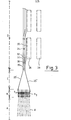
- a guide roll 24 can cooperate with guides of which 25' and 25" are shown with interrupted lines in figure 2 and with solid lines in figure 3. Other such guides are indicated with 33 and 35 in figure 3.
- Each container is provided with a part 26 which is a discharge control member, which means, that when it hits a non-travelling discharge abutment located along the track of the containers, it provokes the opening of gripper 23 and a pivot movement of roll 24 away from the guide indicated with 33 in figure 3. Details of this construction can be found in the United States Patent Specification US-A-4 287 982.
- each balance beam supports a metal sheet 27 that can cooperate with detectors 9 1 ??9 9 controlled by the electro-magnetic damping caused by these sheets.
- detectors 9 1 ??9 9 controlled by the electro-magnetic damping caused by these sheets.
- the corresponding detectors at the right side of the shown balances are indicated with the references 9' 1 ....9' 9 .
- the signals issuing from the detectors 9 are transmitted to the shift registers 11 by means of a processor or switching device 10 to be discussed further on.
- FIG 3 an embodiment of the invention has been shown schematically, in which all containers which by their guide roll are lead into a certain discharge station are discharged in that station. For that reason the discharge station is provided with a delatching set 28, which is able to bring non shown discharge abutments in sequence on the level of the discharge member 26 of an arriving container, the location where this happens being shifted over the distance from one discharge location to the next one, so that the eggs are discharged the one after the another in a row.
- a delatching set 28 which is able to bring non shown discharge abutments in sequence on the level of the discharge member 26 of an arriving container, the location where this happens being shifted over the distance from one discharge location to the next one, so that the eggs are discharged the one after the another in a row.
- a number of guide switches 30 are present, which normally occupy the position shown in solid lines, but under influence of electro-magnets (not shown) they can be brought in the position shown with an interrupted line, because they are pivotable about pivots 31.
- electro-magnets not shown
- a roll 24 engages a guide switch 30 in the position shown in interrupted lines it is urged downwardly until it engages in the guide 33 located below omnibus guide 35 a backward extension 32 of the switch 30. By reason of this the guide switch is reset.
- figure 1 a machine has been shown having sixteen discharge stations to wit eight for the balances at the one side of the yokes 5 and eight for the balances at the other side of the yokes.
- the processing unit 10 is adapted to change the interconnections between the leads from detectors 9 and those leading to the shift registers 11.
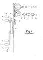
- Figure 4 shows a basic scheme of an embodiment of such a processing unit.
- Figure 4 shows the outputs 9 1 -9 9 of the detectors indicated with the same references and U, and U 2 of two keys (not shown) which indicate three different candling results to wit one when only U 1 has been activated, the second one when only U 2 has been activated and the third one, when both U 1 and U 2 have been activated.
- elements containing compensating delay means have been indicated. These means compensate for the time lapse the objects need to travel from the location where they are when the signals on U 1 or generated to tne location, wnere tnelr containers cooperate with the detectors 9.
- a further purpose of the elements 36 is to generate and issue simultaneously well shaped pulses 1 of a predetermined duration.
- the elements 36 are timed by a non shown clockpulse generator which also clocks other elements of the circuit, for instance the coding device 37 still to be described and the shift registers 11.
- the coding device 37 has four parallel output lines 38, which in a binary coded form carry the information indicating one out of the twelve possible criterion values, namely nine weight values and three candle results to wit U 1 activated, U 2 activated and both U 1 and U 2 activated. Further coding device 37 contains comparator means to make sure that in case a candle result value is received this value overrules the weight value ascertained for the same object.
- the output of coding device 37 is carried by a multiple ) lead to comparators 39, there being two comparators 39 present for each discharge station.
- a second.multiple input of each comperator 39 is fed by a manually servable thumb wheel switch 40, which allows to selectively supply a control voltage to the said second multiple input of comparator 39. If the thumb wheel switches 40 supply a voltage pattern corresponding to that of the output of coding device 37 a pulse is fed to an OR-gate 41.
- the output of the OR-gate 41 is connected to a divider circuit 42 dividing by two. This circuit 42 can be set to transmit each pulse it ) receives on its input or only those which occur with each odd input pulse or only those which occur with each even input pulse.
- the output of divider circuit 42 is carried to a shift register 11 corresponding to those of figure 1.
- the output of the shift register 11 is connected to an one-shot multivibrator 43 which delivers an energizing pulse for an electro-magnet 44 for activating a guide switch 30 of figure 3.
- one of the thumb wheel switches is adjusted to a code value not occurring in the code values issuing from 37, which means that it will never give an output to OR-gate 41. It is also possible to set the thumb wheel switches of the same group on the same code value, because an OR-gate gives also an output if both of its inputs are activated.
- Divider circuit 42 is set in the position in which it transmits each pulse it receives, so that after the delay of shift register 11 electro-magnet 44 is energized for each object having the selected criterion value.
- the first and second thumb wheel switches 40 of a group are adjusted, the one to a first one of said criterion values and the second to the second one.
- the OR-gate 41 transmits a pulse for both these criterion values.
- a comparator 39 belonging to the control circuit for the electro-magnet 44 of the one discharge station and a comparator 39 belonging to the control circuit of the electro-magnet 44 of the other discharge station are set on the related criterion value, it being clear that the other thumb wheel switch of each pair is eithet set on a non existing criterion value or on the same criterion value.
- One of the dividers 42 is set in its dividing position transmitting the odd pulse numbers and the other is set to transmit the even pulse numbers.
- the pulse number is the number of pulses movement of the containers equalling a step from one container to the next, it is not so that each discharge station receives alternately an object of the selected criterion value. Statistically they will, however, in the long run receive almost the same number of objects. The important result is, however, that never two immediately succeeding objects can arrive in the same discharge station, which allows for an important increase of the working speed of the device.
- the coding device 45 corresponds to 37 of figure 4, but its output 46 is connected to a parallel shift register 47, which with each clock pulse shifts a complete code word one step further on. Because such a code word has to encompass twelve criterion values and possibly a thirteenth value corresponding to no object present, a shift . registe with four parallel tracks suffices.
- comparators 48 are mounted at the location corresponding to the different discharge stations. These comparators receive the code word in the related stage of the shift register and compare this word with a word set by means of a data input 49.
- Each comparator 48 corresponds to a comparator 39 of figure 4 and the same features can be used for discharging objects of two different criterion values in the same discharge station, in which instance two comparators 48 are connected to the same output of the shift register 47, each connected to the same discharge station activating electr- magnet 44. In case objects of one criterion value have to be dropped in two or more discharge stations, the output of the related comparator 48 has to be connected to a circuit energizing sequentially the electro-magnets of the different allotted discharge stations.
- the embodiment of figure 5 guarantees that in case the newly allotted discharge station is aval of the previous one, all objects will reach the new one, whereas in case the new station is located amont the previous one only the objects which have already passed the newly allotted one will be dropped in the previous one or if this is/enabled, be discarded.
- the invention is, however, also applicable to known devices, in which all containers are fed through all discharge stations, as for instance shown in the British Patent Specification .GB-A 1 875 797. In such a device the activation of the dis- charge stationscan be treated in the same way.
- a discharge station has a row of activable discharge locations, all controlled with a delay corresponding to their location along the track of the containers, it is possible to have the switching means of the invention change the allotment of a selected criterion value from a first group of discharge locations to another group.
Landscapes
- Sorting Of Articles (AREA)
- Branching, Merging, And Special Transfer Between Conveyors (AREA)
- Discharge Of Articles From Conveyors (AREA)
Applications Claiming Priority (2)
| Application Number | Priority Date | Filing Date | Title |
|---|---|---|---|
| NL8303348A NL8303348A (nl) | 1983-09-30 | 1983-09-30 | Inrichting voor het naar gewicht sorteren van voorwerpen. |
| NL8303348 | 1983-09-30 |
Publications (1)
| Publication Number | Publication Date |
|---|---|
| EP0140425A1 true EP0140425A1 (en) | 1985-05-08 |
Family
ID=19842475
Family Applications (1)
| Application Number | Title | Priority Date | Filing Date |
|---|---|---|---|
| EP84201384A Withdrawn EP0140425A1 (en) | 1983-09-30 | 1984-09-28 | Device for sorting objects |
Country Status (6)
| Country | Link |
|---|---|
| EP (1) | EP0140425A1 (da) |
| JP (1) | JPS60106575A (da) |
| AU (1) | AU3367484A (da) |
| DK (1) | DK467084A (da) |
| ES (1) | ES8506209A1 (da) |
| NL (1) | NL8303348A (da) |
Families Citing this family (1)
| Publication number | Priority date | Publication date | Assignee | Title |
|---|---|---|---|---|
| CN103920655B (zh) * | 2014-04-17 | 2017-06-06 | 南昌光明化验设备有限公司 | 一种编码检测方法 |
Citations (5)
| Publication number | Priority date | Publication date | Assignee | Title |
|---|---|---|---|---|
| GB875797A (en) * | 1957-06-25 | 1961-08-23 | Brecknell Dolman & Rogers Ltd | Improvements relating to the grading of articles, particularly eggs, according to weight |
| US3898435A (en) * | 1974-03-11 | 1975-08-05 | Fmc Corp | Memory device for an egg grading machine |
| US4106628A (en) * | 1976-02-20 | 1978-08-15 | Warkentin Aaron J | Sorter for fruit and the like |
| GB1602911A (en) * | 1978-02-09 | 1981-11-18 | Tamkin Elec Control Services | Distributing apparatus |
| EP0048525A1 (en) * | 1980-09-22 | 1982-03-31 | Administratie- en Automatiseringscentrum Vulcaan B.V. | Grading device |
-
1983
- 1983-09-30 NL NL8303348A patent/NL8303348A/nl not_active Application Discontinuation
-
1984
- 1984-09-27 ES ES536317A patent/ES8506209A1/es not_active Expired
- 1984-09-28 AU AU33674/84A patent/AU3367484A/en not_active Abandoned
- 1984-09-28 EP EP84201384A patent/EP0140425A1/en not_active Withdrawn
- 1984-09-28 DK DK467084A patent/DK467084A/da not_active Application Discontinuation
- 1984-09-29 JP JP20546484A patent/JPS60106575A/ja active Pending
Patent Citations (5)
| Publication number | Priority date | Publication date | Assignee | Title |
|---|---|---|---|---|
| GB875797A (en) * | 1957-06-25 | 1961-08-23 | Brecknell Dolman & Rogers Ltd | Improvements relating to the grading of articles, particularly eggs, according to weight |
| US3898435A (en) * | 1974-03-11 | 1975-08-05 | Fmc Corp | Memory device for an egg grading machine |
| US4106628A (en) * | 1976-02-20 | 1978-08-15 | Warkentin Aaron J | Sorter for fruit and the like |
| GB1602911A (en) * | 1978-02-09 | 1981-11-18 | Tamkin Elec Control Services | Distributing apparatus |
| EP0048525A1 (en) * | 1980-09-22 | 1982-03-31 | Administratie- en Automatiseringscentrum Vulcaan B.V. | Grading device |
Also Published As
| Publication number | Publication date |
|---|---|
| JPS60106575A (ja) | 1985-06-12 |
| DK467084A (da) | 1985-03-31 |
| ES536317A0 (es) | 1985-07-01 |
| AU3367484A (en) | 1985-04-04 |
| NL8303348A (nl) | 1985-04-16 |
| DK467084D0 (da) | 1984-09-28 |
| ES8506209A1 (es) | 1985-07-01 |
Similar Documents
| Publication | Publication Date | Title |
|---|---|---|
| US4320841A (en) | Detection and sorting systems | |
| US4365719A (en) | Radiometric ore sorting method and apparatus | |
| EP0084968B1 (en) | Weighing method and apparatus therefor | |
| US4661917A (en) | Mixing combinatorial counting and weighing method, and apparatus therefor | |
| EP0274002B1 (en) | Combinatorial weighing or counting method | |
| AU637293B2 (en) | Buffer system for the temporary storage of flat objects such as letters, and buffer for use in said buffer system | |
| EP0063056A2 (en) | Combinatorial weighing method and apparatus therefor | |
| CA2123497A1 (en) | Automatic Rotary Sorter | |
| RU2736306C1 (ru) | Устройство для подачи предметов, содержащее вибропитатель | |
| EP0219347B1 (en) | Weighing method and system | |
| JPS55132451A (en) | Speed change control device for automatic speed changer | |
| US4299326A (en) | Weight sorting memory circuit | |
| GB1603860A (en) | Conveyor systems | |
| US4501339A (en) | Automatic weighing apparatus | |
| EP0140425A1 (en) | Device for sorting objects | |
| EP0076167B1 (en) | Combinatorial weighing or counting of articles | |
| EP0060013B1 (en) | Method of and apparatus for sorting objects by weight | |
| EP0064554B1 (en) | Combination weighing method and apparatus | |
| DK158203B (da) | Transportsorteringsanlaeg | |
| EP0074773B1 (en) | Combinatorial weighing method | |
| EP0311845A3 (en) | Bar loader for a multi-chuck machine | |
| US4574897A (en) | Combinatorial weighing apparatus | |
| GB2219268A (en) | Indicators associated with specific articles on a conveyor | |
| JP3367037B2 (ja) | 組合せ計量装置 | |
| JP3915029B2 (ja) | 物品の重量選別装置 |
Legal Events
| Date | Code | Title | Description |
|---|---|---|---|
| PUAI | Public reference made under article 153(3) epc to a published international application that has entered the european phase |
Free format text: ORIGINAL CODE: 0009012 |
|
| AK | Designated contracting states |
Designated state(s): BE DE FR GB IT NL SE |
|
| 17P | Request for examination filed |
Effective date: 19850605 |
|
| 17Q | First examination report despatched |
Effective date: 19861009 |
|
| STAA | Information on the status of an ep patent application or granted ep patent |
Free format text: STATUS: THE APPLICATION IS DEEMED TO BE WITHDRAWN |
|
| 18D | Application deemed to be withdrawn |
Effective date: 19870220 |
|
| RIN1 | Information on inventor provided before grant (corrected) |
Inventor name: PASTERKAMP, KLAAS Inventor name: VAN ESSEN, HENK |