EP0140532B1 - Vorrichtung für die Herstellung von Produkten, die aus mit Harz getränkten umsponnenen Fasern bestehen - Google Patents
Vorrichtung für die Herstellung von Produkten, die aus mit Harz getränkten umsponnenen Fasern bestehen Download PDFInfo
- Publication number
- EP0140532B1 EP0140532B1 EP84305923A EP84305923A EP0140532B1 EP 0140532 B1 EP0140532 B1 EP 0140532B1 EP 84305923 A EP84305923 A EP 84305923A EP 84305923 A EP84305923 A EP 84305923A EP 0140532 B1 EP0140532 B1 EP 0140532B1
- Authority
- EP
- European Patent Office
- Prior art keywords
- mandrel
- filaments
- filament
- resin
- applicator
- Prior art date
- Legal status (The legal status is an assumption and is not a legal conclusion. Google has not performed a legal analysis and makes no representation as to the accuracy of the status listed.)
- Expired
Links
- 239000000835 fiber Substances 0.000 title abstract description 32
- 238000004519 manufacturing process Methods 0.000 title abstract description 11
- 229920005989 resin Polymers 0.000 claims abstract description 126
- 239000011347 resin Substances 0.000 claims abstract description 126
- 239000011148 porous material Substances 0.000 claims abstract description 37
- 239000007788 liquid Substances 0.000 claims abstract description 28
- 238000009954 braiding Methods 0.000 claims description 60
- 238000005470 impregnation Methods 0.000 claims description 26
- 239000011248 coating agent Substances 0.000 claims description 20
- 238000000576 coating method Methods 0.000 claims description 20
- 239000007921 spray Substances 0.000 claims description 16
- 239000002699 waste material Substances 0.000 claims description 7
- 239000012530 fluid Substances 0.000 claims description 6
- 230000000694 effects Effects 0.000 claims description 5
- 230000009471 action Effects 0.000 claims description 4
- 230000000149 penetrating effect Effects 0.000 claims description 2
- 238000005507 spraying Methods 0.000 claims description 2
- 239000011324 bead Substances 0.000 abstract description 2
- 239000002657 fibrous material Substances 0.000 abstract 1
- 229920002430 Fibre-reinforced plastic Polymers 0.000 description 9
- 239000011151 fibre-reinforced plastic Substances 0.000 description 9
- 239000006260 foam Substances 0.000 description 6
- 238000011109 contamination Methods 0.000 description 4
- 230000007246 mechanism Effects 0.000 description 4
- 238000000034 method Methods 0.000 description 4
- 238000005452 bending Methods 0.000 description 3
- 239000002131 composite material Substances 0.000 description 3
- 239000011152 fibreglass Substances 0.000 description 3
- 238000009941 weaving Methods 0.000 description 3
- 230000008901 benefit Effects 0.000 description 2
- 230000002457 bidirectional effect Effects 0.000 description 2
- 230000009977 dual effect Effects 0.000 description 2
- 210000003811 finger Anatomy 0.000 description 2
- 230000005484 gravity Effects 0.000 description 2
- 230000006872 improvement Effects 0.000 description 2
- 230000001788 irregular Effects 0.000 description 2
- 230000014759 maintenance of location Effects 0.000 description 2
- 239000002184 metal Substances 0.000 description 2
- 230000008569 process Effects 0.000 description 2
- 230000002787 reinforcement Effects 0.000 description 2
- 239000012783 reinforcing fiber Substances 0.000 description 2
- 239000007787 solid Substances 0.000 description 2
- 239000002904 solvent Substances 0.000 description 2
- 210000003813 thumb Anatomy 0.000 description 2
- OKTJSMMVPCPJKN-UHFFFAOYSA-N Carbon Chemical compound [C] OKTJSMMVPCPJKN-UHFFFAOYSA-N 0.000 description 1
- 239000004593 Epoxy Substances 0.000 description 1
- JOYRKODLDBILNP-UHFFFAOYSA-N Ethyl urethane Chemical compound CCOC(N)=O JOYRKODLDBILNP-UHFFFAOYSA-N 0.000 description 1
- 229920000271 Kevlar® Polymers 0.000 description 1
- 230000004323 axial length Effects 0.000 description 1
- 230000000740 bleeding effect Effects 0.000 description 1
- 230000008859 change Effects 0.000 description 1
- 238000004140 cleaning Methods 0.000 description 1
- 238000010276 construction Methods 0.000 description 1
- 238000001816 cooling Methods 0.000 description 1
- 230000008878 coupling Effects 0.000 description 1
- 238000010168 coupling process Methods 0.000 description 1
- 238000005859 coupling reaction Methods 0.000 description 1
- 230000007423 decrease Effects 0.000 description 1
- 238000005516 engineering process Methods 0.000 description 1
- 125000003700 epoxy group Chemical group 0.000 description 1
- 238000004880 explosion Methods 0.000 description 1
- 229910002804 graphite Inorganic materials 0.000 description 1
- 239000010439 graphite Substances 0.000 description 1
- 238000010438 heat treatment Methods 0.000 description 1
- 230000000977 initiatory effect Effects 0.000 description 1
- 239000004761 kevlar Substances 0.000 description 1
- 239000004620 low density foam Substances 0.000 description 1
- 239000000463 material Substances 0.000 description 1
- 230000004048 modification Effects 0.000 description 1
- 238000012986 modification Methods 0.000 description 1
- 238000012354 overpressurization Methods 0.000 description 1
- 230000000704 physical effect Effects 0.000 description 1
- 229920003023 plastic Polymers 0.000 description 1
- 239000004033 plastic Substances 0.000 description 1
- 229920000647 polyepoxide Polymers 0.000 description 1
- 229920000728 polyester Polymers 0.000 description 1
- 238000003825 pressing Methods 0.000 description 1
- 230000003014 reinforcing effect Effects 0.000 description 1
- 229920001567 vinyl ester resin Polymers 0.000 description 1
- 125000000391 vinyl group Chemical group [H]C([*])=C([H])[H] 0.000 description 1
- XLYOFNOQVPJJNP-UHFFFAOYSA-N water Substances O XLYOFNOQVPJJNP-UHFFFAOYSA-N 0.000 description 1
- 238000009736 wetting Methods 0.000 description 1
- 238000004804 winding Methods 0.000 description 1
Images


Classifications
-
- D—TEXTILES; PAPER
- D04—BRAIDING; LACE-MAKING; KNITTING; TRIMMINGS; NON-WOVEN FABRICS
- D04C—BRAIDING OR MANUFACTURE OF LACE, INCLUDING BOBBIN-NET OR CARBONISED LACE; BRAIDING MACHINES; BRAID; LACE
- D04C3/00—Braiding or lacing machines
- D04C3/48—Auxiliary devices
-
- B—PERFORMING OPERATIONS; TRANSPORTING
- B29—WORKING OF PLASTICS; WORKING OF SUBSTANCES IN A PLASTIC STATE IN GENERAL
- B29B—PREPARATION OR PRETREATMENT OF THE MATERIAL TO BE SHAPED; MAKING GRANULES OR PREFORMS; RECOVERY OF PLASTICS OR OTHER CONSTITUENTS OF WASTE MATERIAL CONTAINING PLASTICS
- B29B15/00—Pretreatment of the material to be shaped, not covered by groups B29B7/00 - B29B13/00
- B29B15/08—Pretreatment of the material to be shaped, not covered by groups B29B7/00 - B29B13/00 of reinforcements or fillers
- B29B15/10—Coating or impregnating independently of the moulding or shaping step
- B29B15/12—Coating or impregnating independently of the moulding or shaping step of reinforcements of indefinite length
- B29B15/122—Coating or impregnating independently of the moulding or shaping step of reinforcements of indefinite length with a matrix in liquid form, e.g. as melt, solution or latex
-
- B—PERFORMING OPERATIONS; TRANSPORTING
- B29—WORKING OF PLASTICS; WORKING OF SUBSTANCES IN A PLASTIC STATE IN GENERAL
- B29C—SHAPING OR JOINING OF PLASTICS; SHAPING OF MATERIAL IN A PLASTIC STATE, NOT OTHERWISE PROVIDED FOR; AFTER-TREATMENT OF THE SHAPED PRODUCTS, e.g. REPAIRING
- B29C53/00—Shaping by bending, folding, twisting, straightening or flattening; Apparatus therefor
- B29C53/80—Component parts, details or accessories; Auxiliary operations
- B29C53/8008—Component parts, details or accessories; Auxiliary operations specially adapted for winding and joining
- B29C53/8066—Impregnating
-
- D—TEXTILES; PAPER
- D04—BRAIDING; LACE-MAKING; KNITTING; TRIMMINGS; NON-WOVEN FABRICS
- D04C—BRAIDING OR MANUFACTURE OF LACE, INCLUDING BOBBIN-NET OR CARBONISED LACE; BRAIDING MACHINES; BRAID; LACE
- D04C1/00—Braid or lace, e.g. pillow-lace; Processes for the manufacture thereof
- D04C1/06—Braid or lace serving particular purposes
Definitions
- This invention relates to braiding machines for the the production of fiber reinforced plastics (FRP).
- FRP fiber reinforced plastics
- impregnation has been accomplished by using pre-impregnated fibers or by wrapping partially cured (B-stage) resin film around the braid after each layer is completed.
- partially cured resin products are expensive, have limited shelf life even when stored in a freezer and applying the partially cured resin film is cumbersome and slow.
- the invention is concerned with improvements to the normal form of braiding machine for braiding a plurality of filaments about a mandral supported on a base for movement along its axis, the machine including a braid wrapping carrier mounted for rotation about the axis of the carrier and co-axially about the mandrel at a fixed longitudinal position relative to the mandrel movement, means for mounting bobbins of filaments to be braided to the carrier at spaced circumferential positions thereon for bobbin rotation about their axes, and means for rotating the carrier and axially shifting the mandrel to cause the filaments, having their free ends fixed to the mandrel at points axially spaced from the carrier rotation plane, to wrap about the mandrel and to form a braid.
- the axis of the mandrel may be horizontal, the applicator ring may include a vertical wall bearing a small diameter perforations which define the pores through which the resin passes to reach the filaments.
- Dual applicator rings arranged and mounted back to back define a gap corresponding generally to the diameter of the filaments passing therethrough with the finite pores within opposed surfaces of the applicator rings feeding resin for insured resin impregnation of the filaments.
- the vertical walls may flare outwardly away from the gap through which the filaments pass and are impregnated to terminate on the side towards the filament contact area with the mandrel in drain pans and wherein the flared walls bear at least one flexible scraper for pressing the filament against the mandrel causing excess resin to flow back to the drain pans for recirculation or for discard. Draining of the plenum chamber permits subsequent cleaning of the circulation loop of resin by applying compressed air thereto or by forcing solvents through the system including the pores.
- the applicator ring is replaced by at least one imperforate annular guide ring mounted concentrically about the mandrel and axially spaced between the carrier rotation plane and the filament contact area with the mandrel such that the filaments wipe across the surface of the guide ring
- the machine also comprises wall means in juxtaposition to the guide ring which extend generally parallel to the direction of inclination of the filaments wrapped about the filament wrapping surface portion of the guide ring and extending towards the mandrel and terminate in a flexible scraper which is pressed against the periphery of the braid downstream of the area of initial filament contact with the mandrel and spray nozzle means for spraying a fog of minute resin droplets onto the filaments during passage from the guide ring to the mandrel for resin impregnation of the filaments, the scraper wiping any excess coating of resin off the finished braid and the wall means confining any vapors formed by the resin application to the filaments to the area between the guide ring and the mandrel.
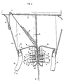
- a first embodiment of the present invention constituting an improved braiding machine for braiding a plurality of filaments about a mandrel and for effecting resin impregnation of those filaments prior to braiding is indicated generally at 10.
- the machine 10 is shown in partial schematic form.
- the schematic representation includes a carriage 12 which is mounted by wheels 16 for rotation over a surface such as floor F, the wheels 16 being journaled to a base 14 of the carriage.
- a motor 15 coupled to wheel 16 functions to drive the carriage across the floor in the direction of arrow 17.
- a horizontal bar 20 Mounted to the carriage by way of vertical uprights 18 is a horizontal bar 20, the bar having affixed thereto, mandrel 22 which in this case is frustoconical in form and about which the filaments are braided to form a braid.
- mandrel 22 which in this case is frustoconical in form and about which the filaments are braided to form a braid.
- the carrier 24 supports a plurality of spools or bobbins 28 for rotation about their axes, from which individual filaments or fibers 32 are removed through eyes 30.
- Each filament 32 is trained about a guide ring of solid or hollow form 34 and the free end of each filament is fixed to the mandrel.
- the carrier 24 is mounted for rotation about its axis and coaxially of mandrel 22 by means of a suitable support mechanism including a plurality of rollers 35 which abut the inner periphery of.carrier 24.
- the drive for the carrier 24 is shown schematically by a pressure roller 37 coupled to an electrical motor 39.
- Motor 39 is powered from a source (not shown) through leads 41. Motor 39 thus drives the carrier in rotation about its axis and coaxially of mandrel 22 in the direction of arrow 43.
- the braiding mandrel 22 may be formed of a low density foam which is very effective in the braiding of FRP products for industrial use as for instance a windmill blade or the like, a fan blade or the like.
- the braiding B is essentially the product being formed, being a resin fiber glass reinforced braiding configured to the exterior configuration of mandrel 22 when the mandrel moves its axial length while braiding is achieved in the direction of arrow 17 through energization of drive motor 15 for carriage 12.
- the braid B is formed by crossing a number of fibers or filaments diagonally in such a way that each strand passes alternately over and under one or more of the others.
- the free end of the filaments 32 are tethered to the periphery of the mandrel at a given point and movement of the mandrel 22 longitudinally while carrier 24 is rotated about its axis effects the braiding.
- Braiding may be effected bidirectionally by movement of the mandrel 22 alternately in opposite directions while rotating carrier 26 bearing the bobbins 28 about its axis.
- the filaments 32 are forced to pass over one or more applicator rings and specifically the porous filament contact surface thereof such that liquid resin may be applied to the filaments to achieve full resin impregnation of the filaments prior to contact with the mandrel 22 and braiding by and between the resin impregnated filaments 32.
- the filaments 32 are forced to pass over one or more applicator rings and specifically the porous filament contact surface thereof such that liquid resin may be applied to the filaments to achieve full resin impregnation of the filaments prior to contact with the mandrel 22 and braiding by and between the resin impregnated filaments 32.
- left and right side applicator rings indicated generally at 36 and 38, respectively.
- applicator ring 36 is shown as effecting resin application to the various filaments 32, however, if the machine 10 is run bidirectionally, the filaments, as they leave the exit end of the applicator ring gap, will alternately wrap about right side applicator ring 38 and be inclined oppositely to the direction shown in Figures 1 and 2.
- the rings 36 and 38 may be formed of sheet metal and bent to the configuration shown.
- Ring 36 includes a central vertical flat filament wrapping surface 36A which bears a plurality of small holes or pores 56 functioning to feed resin to the filaments 32 passing in contact therewith.
- preceding filament wrapping surface 36A is a short curved section 36B which acts as an inlet guide for the filaments while, downstream in the direction of filament movement, a further section 36C flares outwardly and has a circular configuration to guide the filaments 32 as they move away from the applicator ring 36 in the direction of the mandrel.
- Section 36C rises, then descends functioning with a right angle wall 58 as an extension thereof to define a drip pan, indicated generally at 59, for the collection of excess resin R.
- plenum chamber wall 40 and ring 36 form a resin plenum chamber 42 within which resin R under a slight pressure above atmospheric is maintained to effect the desired resin impregnation of the fibers or filaments 32.
- resin R is supplied under pressure to the plenum chamber 42 behind the filament wrapping surface 36A.
- Plenum chamber 42 distributes resin uniformly about the circumference of each of the rings 36 and 38. Application of resin to the plenum chambers 42 may be achieved sequentially, if bidirectional braiding occurs. Resin R is fed under pressure through a hose 48 to a short length tube 44 penetrating wall 40 and opening to the plenum chamber 42. Additionally, a second short length tube 46 opens to the same chamber at the bottom and a drain line or hose 50 is connected thereto for draining the interior of the chamber 42 when the braider is idle, thus returning the resin R to the resin tank 67, Figure 1 through line 50 as shown. At the bottom of resin tank 67, the resin supply line 48 is connected thereto via pump 69 such that resin under slight pressure above atmospheric is maintained within plenum chamber 42.
- paired rings 36 and 38 define a small gap G which is slightly in excess to the diameter of the filaments or fibers 32 passing therebetween for resin application and impregnation.
- Applicator ring 38 is the mirror image of applicator ring 36 and like elements are given like numerical designations. Excess resin which drips off the fibers or filaments 32 is contained by the drip pan and wall 38 and accumulates at the corner or intersection of wall 58 and portion 36C of applicator ring 36 where it returns to the tank via line or hose 62.
- the line or hose 62 is connected via a short length tube 60 to the drip pan 59 and which tube opens to the interior of the drip pan.
- a soft flexible rubber, foam or brush scraper 66 is preferably mounted to wall 58 which contacts the periphery of the braid B in the vicinity of the area where the filaments contact the mandrel to form the braid.
- the scraper may constitute a resilient annular element whose center opening may be somewhat less in diameter than the diameter of the braid encompassing the mandrel so that the inner edge of the annular scraper is actually stretched to insure effective wiping of the exterior surface of the braid as it is formed by the resin impregnated filaments or fibers 32 to remove excess resin. Additionally, this member assists in thorough wetting of the filaments to maximize resin impregnation thereof.
- Scraper 66, wall 58, and the drip pan 59 define a baffle assembly 57 for each applicator ring to each side of the filament path, to baffle the volatile components given off by the resin after resin application thereto and during braiding.
- a suction device (not shown) to wall 58 for instance, such volatile components may be readily removed from the interior of the baffle without contaminating the atmosphere about the machine or the machine components exterior of these baffle assembly elements.
- Drain down valve 53 within line 50 leads back to the resin tank 67, which is normally closed, but it may be opened when braiding operation is terminated for any length of time so that the resin may be returned to the reservoir or resin tank 67. This prevents cured resin clogging the pores or finite holes 56. After the plenum chambers 42 have been drained, the pores 56 may be easily cleaned of resin by applying compressed air to the pores or forcing solvents to pass through the pores.
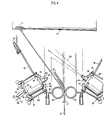
- Fig. 3 in the second embodiment, like elements to those found in the drawings showing the first embodiments are similarly numbered, utilizing prime designations.
- the fibers or filaments 32 move vertically upwardly as indicated by the arrow to the point where they pass between applicator rings 36' and 38', the rings in this case being formed with major portions 36a' and 38a' which are circular in cross section and which merge or continue into drip pan sections 36b' and 38b', respectively, to the left and right of the filament or fiber path.
- An annular strip forming straight wall 70 sealably spans the rear of each of the rings 36, and 38', overlying the area of the perforations of the holes or pores 56' to form plenum chambers 42' with the portion of the rings bearing the holes or pores 56'.
- a resin feed line or hose 48' supplies resin R under pressure as indicated by arrow 52 to the plenum chambers 42' selectively for applicator rings 36' and 38'.
- the plenum chamber 42' for applicator ring 36' is utilized and is supplied with resin for impregnating the filaments 32.
- a short length tube 44' borne by wall 70 and opening to the plenum chamber 42' is connected to the resin feed line 48'.
- a resin drain line or hose 50' permits the use of a solenoid operated valve (not shown) for draining of the contents of the plenum chamber when the braider stops.
- Line 50' connects to the plenum chamber through a short length tube 46' by sealably receiving a portion of that tube.
- a wall member 58' extends from the drip pan and terminates in a flexible rubber or foam scraper (not shown) which rides on the surface of the braid B after braiding to wipe excess resin from the braid and to further insure total impregnation of the filaments with resin.
- the drip pan 59' drains through the short length tube 60' to which drain line or hose 62' is connected as shown returning to the resin tank (not shown) as indicated schematically by arrow 64. Also, the circular.cross section filament wrapping surfaces 36a' and 38a' of the applicator ring are spaced from each other a distance identified by arrow G', thus forming a gap which may be slightly in excess of the diameter of the filaments or fibers 32 passing therethrough.
- Epoxies, polyesters, and vinyl esters of varying viscosities and densities may be employed and different reinforcing fibers 32 such as fiberglass, Kevlar, and graphite may be processed with equal results.
- One or two applicator rings and its attendant structure may be readily added to existing weaving or braiding equipment. Fiber impregnation is continuous during the braiding process. Where multiple layers are desired, the braid can be tied in place and then restarted with the mandrel feeding in the reverse direction as discussed previously. Bidirectional operation significantly increases production rates. Fiber impregnation is thorough and easily controlled. Voids in resin areas are avoided, and resin waste and workplace contamination is minimized.
- the use of the applicator ring and the attendant scrapers along with the drip pan structure permits baffling of the area of impregnation and permits removal of vapors generated in that area through the wall of the baffle mechanism by vacuum application to the interior of the baffle structure.
- the applicator rings may be easily set up, cleaned or modified for optimum performance for a particular choice of resin and reinforcing fiber.
- the machine can accommodate parts that are tapered or irregular in shape as easily as straight cylindrical parts (determined by the configuration of the mandrel).
- baffles By the utilization of integral or attached baffles, excess resin is prevented from dripping onto the braiding machinery and the surrounding workplace and the baffles are purposely formed so as to function in part as drip pans with the drip pans being equipped with drain lines and with the baffles by an attachment to a suction device functioning to contain vapors generated during impregnation which can be removed as they are generated.
- the resin By the use of a resin reservoir or tank, the resin may be pumped under low pressure to the plenum chambers of the applicator rings and the flow may be controlled by conventional means such as regulators and solenoid valves.
- the pressure within the plenum chamber may be increased as necessary to achieve the desired resin content.
- the resin will bulge out of the pore opening but will not flow until the filament passes over the pore.
- the filament 32 which is treated to be easily wetted by the resin, breaks the surface tension and draws out resin by capillary action.
- the resin pressure may be further increased by varying pump speed, causing resin to flow continuously from the pores when a greater resin content is required. Additional modifications to the applicator rings may be made to suit the needs of a particular resin system. For example, dimensions of the plenum chambers may be kept very small to minimize heat buildup in an exothermic resin, or heating or cooling jackets may be added as needed.
- the reinforcing filaments 32 or the resin material may have unique properties which are incompatible with the applicator rings forming the principal components of the embodiments previously described.
- Examples of potential problems include the use of very brittle fibers which could be damaged or snagged when passing over the small holes in the applicator rings or where resins have very low surface tension.
- the elements of the braiding machine which are like those of .the prior embodiments are given like numerical designations.
- the portion of the machine of this embodiment subject to change comprises the components for applying the resin to filaments 32 prior to the filaments being braided about a foam core mandrel, pressure bag, or the like.
- Mandrel 22 is identical to that of the prior embodiments.
- the system utilizes the resin tank, resin pump, and resin circulation components of the prior embodiments.
- the changes involve principally, the replacement of the applicator rings with nonapplicator guide rings 80 which are of circular cross section and in this case hollow although they could be solid.
- the guide rings are separated by a distance or gap g", which gap is somewhat larger than the gaps between the applicator rings since, where the applicator rings function to apply the resin of the prior embodiments to the filament, dual applicator rings may be employed simultaneously to wet opposite sides of the filaments which pass through the gaps.
- the guide rings 80 are provided with smooth outer surfaces which function only to guide the filaments in their travel from the bobbins on the braiding machine carrier 26 to mandrel 22.
- the guide rings 80 are supported by cylindrical members 84 on their outside surfaces remote from the filament path defined by rings and gap g".
- Inclined frustoconical baffle walls 86 extend therefrom or are integral therewith, the frustoconical walls 86 terminating in flexible rubber or foam scrapers 66 of annular form similar to those of the prior embodiments.
- Holes 88 are formed within the frustoconical baffle walls 86 at various circumferential locations, within which are mounted spray nozzle units indicated generally at 90 by way of a nozzle mounting structures 92 consisting of multiple clamps 94.
- the clamps 94 involve spaced arcuate clamping fingers 96 and 98 through which pass the shaft portion of an adjusting thumb screw 100. Rotating the thumb screw increases or decreases the pressure exerted by the fingers 96 and 98 on the nozzle manifold block 102 of the nozzle 90.
- a atomizer or spray nozzle 104 Projecting outwardly from one end of the nozzle manifold block 102 is a atomizer or spray nozzle 104.
- These nozzle units are commercially available such as the Flow Sonic (Registered Trade Mark) Twin Fluid atomizers manufactured by Fluid Kinetics Incorporated of Fairfield, Ohio.
- the nozzle units 90 are characterized by their production of a wet "fog" of very fine resin droplets which function to quickly wet out the fibers 32 without impinging on the fibers at high velocity and thus eliminate the possibility of fracture of the filaments or fibers 32 prior to braiding.
- Their spray nozzles 104 produce a spray pattern of resin droplets as indicated at a generally at 106.
- the resin is fed, as indicated by arrow 108, through a resin feed line or hose 110 to the nozzle manifold block 102, the hose is being coupled thereto by a tube or a fitting 112.
- air under pressure may be fed as indicated by arrow 114 through an air feed line or hose 160 to the block and hence to the atomizer or spray nozzle 104, through a coupling or tube 118.
- Exemplary of the practical use of the modified braiding machine of the present invention is the production of complex geometry parts, i.e., fiberglass rotor blades for modern wind turbines.
- a standard commercially available 144 carrier braider, such as Mossberg Number 2 was modified to form the embodiment of Figures 1 and 2, set up for horizontal operation and the motor driven carriage 12 was used to feed mandrel 22 through the center of the braiding machine 10.
- the mandrel comprised a low density urethane foam core molded to the inside dimensions of the wind turbine blade which was purposely mounted to the carriage 12 as an expendable mandrel.
- a metal root end retention bushing (not shown) provided with a number of small pins extending from it was bonded to one end of the foam core mandrel, thus the retention fitting was built into the braided structure in a single operation with no finishing operations required. Since a wind turbine blade is subjected to high bending loads the braiding machine was required to produce a triaxial braid with a large percentage of unidirectional fibers.
- the Mossberg Number 2 braider up to 72 warp (longitudinal) filaments or fibers 32 were fed through the centers of the horn gears (not shown) on the 144 carrier braider to provide great bending strength and stiffness to the molded product.
- the over and under bias braided filaments 32 provided torsional stiffness and improved through-thickness strength compared to conventional fiber orientations.
- the use of warp filaments is important in optimizing the use of braiding for wind turbine blades by increasing the bending strength and allowing greater ability for aerial elastic tailoring.
- the braiding operation was found to be extremely fast in comparison to prior techniques operating at a standard speed of 32 picks per minute in a blade with a construction of 4.5 picks per inch was found to feed through the braider at nearly 6 feet per minute (2mm/min).
Landscapes
- Engineering & Computer Science (AREA)
- Textile Engineering (AREA)
- Mechanical Engineering (AREA)
- Manufacturing & Machinery (AREA)
- Braiding, Manufacturing Of Bobbin-Net Or Lace, And Manufacturing Of Nets By Knotting (AREA)
- Moulding By Coating Moulds (AREA)
- Reinforced Plastic Materials (AREA)
Claims (9)
Priority Applications (1)
| Application Number | Priority Date | Filing Date | Title |
|---|---|---|---|
| AT84305923T ATE35394T1 (de) | 1983-09-02 | 1984-08-30 | Vorrichtung fuer die herstellung von produkten, die aus mit harz getraenkten umsponnenen fasern bestehen. |
Applications Claiming Priority (2)
| Application Number | Priority Date | Filing Date | Title |
|---|---|---|---|
| US06/528,929 US4494436A (en) | 1983-09-02 | 1983-09-02 | Apparatus for manufacturing resin impregnated fiber braided products |
| US528929 | 1983-09-02 |
Publications (2)
| Publication Number | Publication Date |
|---|---|
| EP0140532A1 EP0140532A1 (de) | 1985-05-08 |
| EP0140532B1 true EP0140532B1 (de) | 1988-06-29 |
Family
ID=24107800
Family Applications (1)
| Application Number | Title | Priority Date | Filing Date |
|---|---|---|---|
| EP84305923A Expired EP0140532B1 (de) | 1983-09-02 | 1984-08-30 | Vorrichtung für die Herstellung von Produkten, die aus mit Harz getränkten umsponnenen Fasern bestehen |
Country Status (4)
| Country | Link |
|---|---|
| US (1) | US4494436A (de) |
| EP (1) | EP0140532B1 (de) |
| AT (1) | ATE35394T1 (de) |
| DE (1) | DE3472378D1 (de) |
Families Citing this family (55)
| Publication number | Priority date | Publication date | Assignee | Title |
|---|---|---|---|---|
| US5006291A (en) * | 1985-04-24 | 1991-04-09 | Plas/Steel Products, Inc. | Method for making fiber reinforced plastic tubing |
| DE3521228A1 (de) * | 1985-06-13 | 1986-12-18 | Basf Ag, 6700 Ludwigshafen | Verfahren und vorrichtung zur kontinuierlichen herstellung von halbzeug aus faserverstaerkten kunststoffen |
| US4846908A (en) * | 1987-04-03 | 1989-07-11 | E. I. Du Pont De Nemours And Company | Process for preparing a fiber reinforced resin matrix preform |
| CA1309283C (en) * | 1988-02-02 | 1992-10-27 | Ronald Frank Mcconnell | In-line consolidation of braided structures |
| US5127307A (en) * | 1989-09-27 | 1992-07-07 | Gould Inc. | Method of manufacture of articles employing tubular braids and resin applicator used therein |
| US5217770A (en) * | 1991-08-15 | 1993-06-08 | The B. F. Goodrich Company | Braided shaped filamentary structures and methods of making |
| US5203249A (en) * | 1991-08-30 | 1993-04-20 | United Technologies Corporation | Multiple mandrel/braiding ring braider |
| CA2077130C (en) * | 1991-09-04 | 2003-04-29 | Edward Lee Morris | Carbon fiber reinforced carbon/carbon composite and method of its manufacture |
| US5362344A (en) * | 1993-02-03 | 1994-11-08 | Avco Corporation | Ducted support housing assembly |
| US5476027A (en) * | 1993-03-23 | 1995-12-19 | Murata Kikai Kabushiki Kaisha | Braider |
| US5468327A (en) * | 1994-01-24 | 1995-11-21 | University Of Massachusetts Lowell | Method and device for continuous formation of braid reinforced thermoplastic structural and flexible members |
| MY112441A (en) * | 1994-03-17 | 2001-06-30 | Shell Int Research | A process of melt impregnation |
| DE4413501A1 (de) * | 1994-04-19 | 1995-10-26 | Inst Verbundwerkstoffe Gmbh | Verfahren und Vorrichtung zur Faserbündelimprägnierung |
| US5662855A (en) * | 1994-05-17 | 1997-09-02 | The B.F. Goodrich Company | Method of making near net shaped fibrous structures |
| DE19602726A1 (de) * | 1996-01-26 | 1997-07-31 | Plastobras Holding S A | Vorrichtung zur Herstellung eines schlauch- oder rohrartigen Formkörpers aus einem faserverstärkten Reaktionsharz |
| US5904087A (en) * | 1997-07-28 | 1999-05-18 | Foster-Miller, Inc. | Braiding machine carrier with clutch |
| DE69812514T2 (de) * | 1997-09-09 | 2004-01-29 | Murata Machinery Ltd | Führer zum Stabilisieren der Flechtformung an einer Flechtmaschine |
| US6182398B1 (en) | 1997-11-21 | 2001-02-06 | A&P Technology, Inc. | Curved air beam |
| US6128998A (en) | 1998-06-12 | 2000-10-10 | Foster Miller, Inc. | Continuous intersecting braided composite structure and method of making same |
| US6510961B1 (en) | 1999-04-14 | 2003-01-28 | A&P Technology | Integrally-reinforced braided tubular structure and method of producing the same |
| US6395210B1 (en) | 1999-05-12 | 2002-05-28 | A&P Technology, Inc. | Pultrusion method and device for forming composites using pre-consolidated braids |
| US6383293B1 (en) | 1999-11-30 | 2002-05-07 | Owens Corning Fiberglas Technology, Inc. | Applicator for coating fibrous materials |
| MXPA03000732A (es) * | 2000-07-28 | 2003-07-14 | Univ Brigham Young | Estructura armada isometrica. |
| RU2177917C1 (ru) * | 2001-02-22 | 2002-01-10 | Колдыбаев Сергей Глебович | Устройство для пропитки волокон |
| TW565647B (en) * | 2001-08-17 | 2003-12-11 | Univ Brigham Young | Method and apparatus for fabricating complex, composite structures from continuous fibers |
| GB0213161D0 (en) * | 2002-06-07 | 2002-07-17 | Short Brothers Plc | A fibre reinforced composite component |
| DE10229078B4 (de) * | 2002-06-28 | 2006-07-13 | Contitech Luftfedersysteme Gmbh | Vorrichtung zum Führen einzelner Verstärkungsfäden |
| TWI225531B (en) * | 2002-09-04 | 2004-12-21 | Univ Brigham Young | Three-dimensional grid panel |
| DE10259593B4 (de) * | 2002-12-19 | 2010-02-25 | Daimler Ag | Vorrichtung und Verfahren zum Beflechten eines Kerns |
| FR2874852B1 (fr) * | 2004-09-03 | 2008-02-22 | Digital Composite Systems Sarl | Procede de fabrication d'une piece allongee creuse en materiau composite telle qu'une pale d'eolienne comprenant une coque tressee, pale d'eolienne et machine de tressage |
| FR2882681B1 (fr) * | 2005-03-03 | 2009-11-20 | Coriolis Composites | Tete d'application de fibres et machine correspondante |
| US7547371B2 (en) * | 2005-03-31 | 2009-06-16 | Jason Christensen | Composite architectural column |
| DE102005027879A1 (de) * | 2005-06-09 | 2006-12-14 | Deutsche Institute für Textil- und Faserforschung Stuttgart - Stiftung des öffentlichen Rechts | Stabförmiger Faserverbundwerkstoff, Verfahren und Vorrichtung zu seiner Herstellung |
| WO2007022218A2 (en) * | 2005-08-16 | 2007-02-22 | Brigham Young University | Apparatus, system, and method for filamentary composite lattice structure manufacturing |
| RU2301148C1 (ru) * | 2005-09-30 | 2007-06-20 | Закрытое акционерное общество "Завод электротехнического оборудования" (ЗАО "ЗЭТО") | Способ изготовления крупногабаритных толстостенных полимерных композитных деталей |
| RU2322350C2 (ru) * | 2006-05-02 | 2008-04-20 | Открытое акционерное общество Научно-производственное объединение "Искра" | Устройство для изготовления изделия из композиционных материалов методом намотки |
| WO2009006252A1 (en) * | 2007-07-03 | 2009-01-08 | 3M Innovative Properties Company | Method of forming composite optical film |
| JP5540616B2 (ja) * | 2009-09-10 | 2014-07-02 | 村田機械株式会社 | フィラメントワインディング装置 |
| FR2956415B1 (fr) * | 2010-02-18 | 2012-04-13 | Messier Dowty Sa | Procede d'exploitation d'une machine de tressage de fibres renforcantes. |
| US8511214B2 (en) | 2011-04-21 | 2013-08-20 | Aga Medical Corporation | Tubular structure and method for making the same |
| US8844873B2 (en) * | 2011-09-23 | 2014-09-30 | The Boeing Company | Stabilizer torque box assembly and method |
| US9366536B2 (en) | 2013-01-15 | 2016-06-14 | Honeywell International Inc. | Method and apparatus for producing fiber optic gyroscope sensing coil using B-stage adhesive coated optical fiber |
| US9839253B2 (en) | 2014-12-10 | 2017-12-12 | Nike, Inc. | Last system for braiding footwear |
| US10060057B2 (en) | 2015-05-26 | 2018-08-28 | Nike, Inc. | Braiding machine with non-circular geometry |
| US10280538B2 (en) | 2015-05-26 | 2019-05-07 | Nike, Inc. | Braiding machine and method of forming an article incorporating a moving object |
| US10238176B2 (en) | 2015-05-26 | 2019-03-26 | Nike, Inc. | Braiding machine and method of forming a braided article using such braiding machine |
| US9920462B2 (en) | 2015-08-07 | 2018-03-20 | Nike, Inc. | Braiding machine with multiple rings of spools |
| EP3384199A4 (de) * | 2015-12-02 | 2018-12-05 | Other Lab, LLC | Systeme und verfahren zum flechten von auskleidungen und zum auftragen von harzen |
| US10953598B2 (en) * | 2016-11-04 | 2021-03-23 | Continuous Composites Inc. | Additive manufacturing system having vibrating nozzle |
| US10180000B2 (en) | 2017-03-06 | 2019-01-15 | Isotruss Industries Llc | Composite lattice beam |
| US10584491B2 (en) | 2017-03-06 | 2020-03-10 | Isotruss Industries Llc | Truss structure |
| USD896401S1 (en) | 2018-03-06 | 2020-09-15 | Isotruss Industries Llc | Beam |
| USD895157S1 (en) | 2018-03-06 | 2020-09-01 | IsoTruss Indsutries LLC | Longitudinal beam |
| CN115352036B (zh) * | 2022-09-05 | 2023-09-29 | 江苏省特种设备安全监督检验研究院 | 一种可调节喷头与刮板的碳纤维缠绕装置 |
| US12448708B2 (en) * | 2024-02-15 | 2025-10-21 | Rtx Corporation | Extended inner profile for mandrel for use in forming braided CMC structures |
Family Cites Families (10)
| Publication number | Priority date | Publication date | Assignee | Title |
|---|---|---|---|---|
| US1110671A (en) * | 1912-03-26 | 1914-09-15 | Henry Zenas Cobb | Manufacture of rubber hose. |
| US1098257A (en) * | 1912-05-17 | 1914-05-26 | Francis Jeremiah Healey | Machine for making and treating braids. |
| US3444019A (en) * | 1963-02-08 | 1969-05-13 | Shell Oil Co | Method for the manufacture of reinforced plastic pipes |
| US3616061A (en) * | 1970-02-05 | 1971-10-26 | Ciba Geigy Corp | Apparatus for making curved wound articles |
| US3653295A (en) * | 1970-04-30 | 1972-04-04 | Johns Manville | Method of providing a lubricant to braided cord |
| DE2106191C3 (de) * | 1971-02-10 | 1978-11-09 | Continental Gummi-Werke Ag, 3000 Hannover | Rundflechtmaschine zum Umflechten eines Schlauchrohlings |
| US3993531A (en) * | 1973-01-19 | 1976-11-23 | Telefonaktiebolaget L M Ericsson | Device for wrapping insulation tape about an elongate conductor |
| NL7610811A (nl) * | 1976-09-29 | 1978-03-31 | Lundbergs Fab Ab N | Inrichting voor de vervaardiging van gewapende buizen. |
| SE7703963L (sv) * | 1977-04-05 | 1978-10-06 | Berg A Einar | Anordning for framstellning av stavar och ror av bindemedel och armering |
| DE2855638C2 (de) * | 1978-12-22 | 1983-07-28 | Messerschmitt-Bölkow-Blohm GmbH, 8000 München | Verfahren zum Herstellen von länglichen Wickelkörpern aus Faserverbundwerkstoff |
-
1983
- 1983-09-02 US US06/528,929 patent/US4494436A/en not_active Expired - Lifetime
-
1984
- 1984-08-30 EP EP84305923A patent/EP0140532B1/de not_active Expired
- 1984-08-30 AT AT84305923T patent/ATE35394T1/de active
- 1984-08-30 DE DE8484305923T patent/DE3472378D1/de not_active Expired
Also Published As
| Publication number | Publication date |
|---|---|
| US4494436A (en) | 1985-01-22 |
| ATE35394T1 (de) | 1988-07-15 |
| EP0140532A1 (de) | 1985-05-08 |
| DE3472378D1 (en) | 1988-08-04 |
Similar Documents
| Publication | Publication Date | Title |
|---|---|---|
| EP0140532B1 (de) | Vorrichtung für die Herstellung von Produkten, die aus mit Harz getränkten umsponnenen Fasern bestehen | |
| KR0133063B1 (ko) | 보강섬유 및 열가소성 유기물로된 실 또는 스트립 제조방법 및 장치 | |
| CN112157926B (zh) | 一种纤维增强复合材料缠绕成型设备及其缠绕成型工艺 | |
| US3378427A (en) | Apparatus for winding articles | |
| WO2017150186A1 (ja) | 3次元プリンティング装置及び3次元プリンティング方法 | |
| US4308999A (en) | Method and apparatus for longitudinally reinforcing continuously generated plastic pipe | |
| JP6850448B2 (ja) | シート材押圧装置、シート材押圧方法、押圧ローラ及びシート材の製造方法 | |
| JP3685335B2 (ja) | 繊維束含浸方法及び装置 | |
| CN1283872C (zh) | 处理纤维材料的方法和设备 | |
| US4174243A (en) | Method and apparatus for wiping resin from filament wound pipe | |
| US3150026A (en) | Apparatus for placing and bonding weft strands to continuous warp strands | |
| JP2000334853A (ja) | ブレイダーによる繊維強化圧力容器の連続生産システム | |
| CN116133824A (zh) | 用于生产包括至少一个缠绕纤维增强聚合物层的复合部件的装置和方法 | |
| JP3698268B2 (ja) | Frp筒体の製造方法および製造装置 | |
| CS216154B2 (en) | Method of making the rotary hollow articlac from plastic material reinforced by glass fibres and device for executing the same | |
| FI79518B (fi) | Foerfarande och anordning foer framstaellning av glasfiberprodukter, t.ex. mattor, garn och foergarn. | |
| JP2990933B2 (ja) | Frp製円筒物の製造方法及び装置 | |
| JPH0515166B2 (de) | ||
| JPH0615028Y2 (ja) | 強化繊維合成樹脂管の成形装置 | |
| CA2040806A1 (en) | Apparatus for manufacturing resin impregnated fiber braided products | |
| JP3339161B2 (ja) | Frp製管状体の製造装置および製造方法 | |
| CN113021967B (zh) | 一种竹纤维预处理设备 | |
| EP0040103B1 (de) | Harzimprägniervorrichtung | |
| JP3268105B2 (ja) | Frp製管状体の製造装置および製造方法 | |
| JP2025504651A (ja) | 樹脂塗布を伴うフィラメントワインディングマシンおよび方法 |
Legal Events
| Date | Code | Title | Description |
|---|---|---|---|
| PUAI | Public reference made under article 153(3) epc to a published international application that has entered the european phase |
Free format text: ORIGINAL CODE: 0009012 |
|
| AK | Designated contracting states |
Designated state(s): AT BE CH DE FR GB IT LI LU NL SE |
|
| 17P | Request for examination filed |
Effective date: 19851028 |
|
| 17Q | First examination report despatched |
Effective date: 19860918 |
|
| RAP1 | Party data changed (applicant data changed or rights of an application transferred) |
Owner name: U.S. COMPOSITES, CORP. |
|
| GRAA | (expected) grant |
Free format text: ORIGINAL CODE: 0009210 |
|
| AK | Designated contracting states |
Kind code of ref document: B1 Designated state(s): AT BE CH DE FR GB IT LI LU NL SE |
|
| REF | Corresponds to: |
Ref document number: 35394 Country of ref document: AT Date of ref document: 19880715 Kind code of ref document: T |
|
| ITF | It: translation for a ep patent filed | ||
| REF | Corresponds to: |
Ref document number: 3472378 Country of ref document: DE Date of ref document: 19880804 |
|
| ET | Fr: translation filed | ||
| PLBE | No opposition filed within time limit |
Free format text: ORIGINAL CODE: 0009261 |
|
| STAA | Information on the status of an ep patent application or granted ep patent |
Free format text: STATUS: NO OPPOSITION FILED WITHIN TIME LIMIT |
|
| 26N | No opposition filed | ||
| ITTA | It: last paid annual fee | ||
| EPTA | Lu: last paid annual fee | ||
| EAL | Se: european patent in force in sweden |
Ref document number: 84305923.9 |
|
| PGFP | Annual fee paid to national office [announced via postgrant information from national office to epo] |
Ref country code: LU Payment date: 19960701 Year of fee payment: 13 |
|
| PGFP | Annual fee paid to national office [announced via postgrant information from national office to epo] |
Ref country code: SE Payment date: 19960715 Year of fee payment: 13 Ref country code: FR Payment date: 19960715 Year of fee payment: 13 |
|
| PGFP | Annual fee paid to national office [announced via postgrant information from national office to epo] |
Ref country code: NL Payment date: 19960716 Year of fee payment: 13 Ref country code: DE Payment date: 19960716 Year of fee payment: 13 |
|
| PGFP | Annual fee paid to national office [announced via postgrant information from national office to epo] |
Ref country code: AT Payment date: 19960718 Year of fee payment: 13 |
|
| PGFP | Annual fee paid to national office [announced via postgrant information from national office to epo] |
Ref country code: CH Payment date: 19960719 Year of fee payment: 13 |
|
| PGFP | Annual fee paid to national office [announced via postgrant information from national office to epo] |
Ref country code: GB Payment date: 19960724 Year of fee payment: 13 |
|
| PGFP | Annual fee paid to national office [announced via postgrant information from national office to epo] |
Ref country code: BE Payment date: 19960726 Year of fee payment: 13 |
|
| PG25 | Lapsed in a contracting state [announced via postgrant information from national office to epo] |
Ref country code: LU Free format text: LAPSE BECAUSE OF NON-PAYMENT OF DUE FEES Effective date: 19970830 Ref country code: GB Free format text: LAPSE BECAUSE OF NON-PAYMENT OF DUE FEES Effective date: 19970830 Ref country code: AT Free format text: LAPSE BECAUSE OF NON-PAYMENT OF DUE FEES Effective date: 19970830 |
|
| PG25 | Lapsed in a contracting state [announced via postgrant information from national office to epo] |
Ref country code: SE Free format text: LAPSE BECAUSE OF NON-PAYMENT OF DUE FEES Effective date: 19970831 Ref country code: LI Free format text: LAPSE BECAUSE OF NON-PAYMENT OF DUE FEES Effective date: 19970831 Ref country code: CH Free format text: LAPSE BECAUSE OF NON-PAYMENT OF DUE FEES Effective date: 19970831 Ref country code: BE Free format text: LAPSE BECAUSE OF NON-PAYMENT OF DUE FEES Effective date: 19970831 |
|
| BERE | Be: lapsed |
Owner name: U.S. COMPOSITES CORP. Effective date: 19970831 |
|
| PG25 | Lapsed in a contracting state [announced via postgrant information from national office to epo] |
Ref country code: NL Free format text: LAPSE BECAUSE OF NON-PAYMENT OF DUE FEES Effective date: 19980301 |
|
| REG | Reference to a national code |
Ref country code: CH Ref legal event code: PL |
|
| GBPC | Gb: european patent ceased through non-payment of renewal fee |
Effective date: 19970830 |
|
| PG25 | Lapsed in a contracting state [announced via postgrant information from national office to epo] |
Ref country code: FR Free format text: LAPSE BECAUSE OF NON-PAYMENT OF DUE FEES Effective date: 19980430 |
|
| PG25 | Lapsed in a contracting state [announced via postgrant information from national office to epo] |
Ref country code: DE Free format text: LAPSE BECAUSE OF NON-PAYMENT OF DUE FEES Effective date: 19980501 |
|
| EUG | Se: european patent has lapsed |
Ref document number: 84305923.9 |
|
| NLV4 | Nl: lapsed or anulled due to non-payment of the annual fee |
Effective date: 19980301 |
|
| REG | Reference to a national code |
Ref country code: FR Ref legal event code: ST |