EP0140574B1 - Optisches Verfahren und Vorrichtung zum Messen von kleinen Verschiebungen - Google Patents
Optisches Verfahren und Vorrichtung zum Messen von kleinen Verschiebungen Download PDFInfo
- Publication number
- EP0140574B1 EP0140574B1 EP84306497A EP84306497A EP0140574B1 EP 0140574 B1 EP0140574 B1 EP 0140574B1 EP 84306497 A EP84306497 A EP 84306497A EP 84306497 A EP84306497 A EP 84306497A EP 0140574 B1 EP0140574 B1 EP 0140574B1
- Authority
- EP
- European Patent Office
- Prior art keywords
- light
- reflective element
- displacement
- path
- reflective
- Prior art date
- Legal status (The legal status is an assumption and is not a legal conclusion. Google has not performed a legal analysis and makes no representation as to the accuracy of the status listed.)
- Expired - Lifetime
Links
- 238000006073 displacement reaction Methods 0.000 title claims description 28
- 238000000034 method Methods 0.000 title claims description 20
- 230000003287 optical effect Effects 0.000 title claims description 13
- 230000001419 dependent effect Effects 0.000 claims 1
- 238000000576 coating method Methods 0.000 description 4
- 239000011248 coating agent Substances 0.000 description 2
- 230000035945 sensitivity Effects 0.000 description 2
- 230000005540 biological transmission Effects 0.000 description 1
- 239000011521 glass Substances 0.000 description 1
- 239000000543 intermediate Substances 0.000 description 1
- 238000012986 modification Methods 0.000 description 1
- 230000004048 modification Effects 0.000 description 1
- 230000000284 resting effect Effects 0.000 description 1
- 238000007789 sealing Methods 0.000 description 1
- 125000006850 spacer group Chemical group 0.000 description 1
Images
Classifications
-
- G—PHYSICS
- G01—MEASURING; TESTING
- G01D—MEASURING NOT SPECIALLY ADAPTED FOR A SPECIFIC VARIABLE; ARRANGEMENTS FOR MEASURING TWO OR MORE VARIABLES NOT COVERED IN A SINGLE OTHER SUBCLASS; TARIFF METERING APPARATUS; MEASURING OR TESTING NOT OTHERWISE PROVIDED FOR
- G01D5/00—Mechanical means for transferring the output of a sensing member; Means for converting the output of a sensing member to another variable where the form or nature of the sensing member does not constrain the means for converting; Transducers not specially adapted for a specific variable
- G01D5/26—Mechanical means for transferring the output of a sensing member; Means for converting the output of a sensing member to another variable where the form or nature of the sensing member does not constrain the means for converting; Transducers not specially adapted for a specific variable characterised by optical transfer means, i.e. using infrared, visible, or ultraviolet light
- G01D5/32—Mechanical means for transferring the output of a sensing member; Means for converting the output of a sensing member to another variable where the form or nature of the sensing member does not constrain the means for converting; Transducers not specially adapted for a specific variable characterised by optical transfer means, i.e. using infrared, visible, or ultraviolet light with attenuation or whole or partial obturation of beams of light
-
- G—PHYSICS
- G01—MEASURING; TESTING
- G01D—MEASURING NOT SPECIALLY ADAPTED FOR A SPECIFIC VARIABLE; ARRANGEMENTS FOR MEASURING TWO OR MORE VARIABLES NOT COVERED IN A SINGLE OTHER SUBCLASS; TARIFF METERING APPARATUS; MEASURING OR TESTING NOT OTHERWISE PROVIDED FOR
- G01D5/00—Mechanical means for transferring the output of a sensing member; Means for converting the output of a sensing member to another variable where the form or nature of the sensing member does not constrain the means for converting; Transducers not specially adapted for a specific variable
- G01D5/26—Mechanical means for transferring the output of a sensing member; Means for converting the output of a sensing member to another variable where the form or nature of the sensing member does not constrain the means for converting; Transducers not specially adapted for a specific variable characterised by optical transfer means, i.e. using infrared, visible, or ultraviolet light
- G01D5/268—Mechanical means for transferring the output of a sensing member; Means for converting the output of a sensing member to another variable where the form or nature of the sensing member does not constrain the means for converting; Transducers not specially adapted for a specific variable characterised by optical transfer means, i.e. using infrared, visible, or ultraviolet light using optical fibres
Definitions
- This invention relates to optical methods and sensors for measuring the displacement of an object.
- a detector is arranged to measure light received by the detector from a light source, and the object is arranged such that displacement of the object in a direction transverse to the light path between the source and detector will cause a variation in the amount of light measured by the detector so that variation in the amount of light measured by the detector is indicative of the displacement of the object.
- a method is described, for example, in US-A-4,302,109, US-A-4,091,280 and US-A-3,983,391.
- Such a method suffers the disadvantage that the amount of light measured by the detector will also vary according to the sensitivity of the detector, the light output of source, and other variations within the light path, these all being factors which may vary with time. Variations in the sensitivity of the detector, and changes in the output of the light source may be partially compensated for by the use of a reference beam. However it is difficult to compensate for variations in the light path.
- a method of measuring displacement of an object comprising: directing light within each of at least two discrete wavelength bands onto a detector along a path including a member having light transmissive or reflective properties which vary spatially in a different manner for light within each said wavelength band in at least one direction transverse to said path; utilising the output of said detector to provide an indication of the quantity of light transmitted within each of said wavelength bands along said path; and determining the change in the ratio of said indications resulting from displacement of the object.
- an optical method of measuring displacement of an object comprising: directing light within each of at least two discrete wavelength bands onto a detector along a path including a member having light transmissive or reflective properties which vary spatially in a different manner for light within each said wavelength band in at least one direction transverse to said path; utilising the output of said detector to provide an indication of the quantity of light transmitted within each of said wavelength bands along said light path; and determining the change in the ratio of said indications resulting from displacement of the object, characterised in that said path further includes a second member having light transmissive or reflective properties which vary spatially in the same manner for light in each said wavelength band in at least one direction transverse to said path, said two members being arranged so that displacement of the object causes said two members to be displaced relative to one another in a direction transverse to said path.
- the invention also provides a sensor for use in an optical method of measuring displacement of an object according to the invention comprising: a light guide; a concave light reflective element positioned such that one end of said light guide is directed towards said reflective element from a position substantially at the centre of curvature of said reflective element; a light transmissive member interposed between said one end of said light guide and said reflective element, one of said member and said reflective element having transmissive or reflective properties as appropriate which for light within each of at least two different wavelength bands vary spatially in at least one direction transverse to the optical axis of said reflective element in a different manner for light in each said wavelength band, and the other of said member and said reflective element having light transmissive or reflective properties, as appropriate, which vary spatially in said one direction in the same manner for light in each said wavelength band, said member and said reflective element being supported so as to allow them to be displaced relative to each other in said one direction with displacement of said object.
- said member and reflective element are arranged for relative rotary displacement with displacement of said object.
- EP-A-0095273 which falls within the terms of Article 54 (3) EPC.
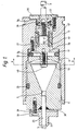
- the sensor to be described is particularly adapted for measuring the angular displacement of a shaft 3 about its longitudinal axis.
- the sensor includes a light guide 5 in the form of a fibre-optic monofilament, one free end 7 of which lies at the centre of curvature of a piano-concave reflective element 9.
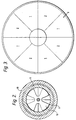
- the reflective surface of the element 9 has applied to it an alternating pattern of two different reflective coatings, the two coatings being indicated as 1 and 2 in Figure 3.
- the first coating 1 is designed to reflect more than 80% of light in the waveband 790 - 840 nm, and to reflect less than 1 % of light in the waveband 880 - 930 nm.
- the second coating 2 is designed to reflect more than 80% of light in the waveband 880 - 930 nm, and to reflect less than 1% of light in the waveband 790 - 840 nm.
- the reflective element 9 is supported by two parts 11, 13 of a housing, the plane back surface of the reflective element resting, via an '0' ring 15, on a keep plate 17 attached by screws 21 to the part 13, the perimeter of the concave front surface of the reflective element being held by an appropriately sloping forward edge of the part 11.
- the part 11 is a screw fit within the part 13, and '0' ring 23 being trapped between the two parts.
- the end 7 of the light guide 5 is located at the apex of a conical cavity within the part 11.
- the light guide extends from its end 7 in a ferrule 25 through an aperture through the part 11 and through a flange 27, the flange being secured by screws 33 onto the part 11 with an intermediates shim 29 and an '0' ring 31.
- An extension 3a of the shaft passes through an end plate 35 secured by screws 37 to the part 13, to extend into a cavity within the part 13, where it is contacted by the sealing lip of a "heart" seal 39.
- a further extension 3b, of the shaft enters into a further cavity with the part 13 where it is rotatably supported by bearings 41, 43 separated by inner 45 and outer 47 spacers.
- the shaft 3 then terminates in a nose portion 3c which passes through an aperture in the reflective element 9 into the conical cavity within the part 11.
- Attached to the nose portion 3c with a screw 49, such that it lies between the end 7 of the light guide 5, and the reflective element 9 is a metallic shutter 51 in the form of a Maltese Cross painted matt black as best shown in Figure 2.
- the light guide 5 is connected to a unit (not shown) containing electronic, electro-optic and optical components.
- Light within the two wavebands 790 - 840 nm, and 880 - 930 nm is shone down the light guide 5 to be reflected by the reflective element 9 and pass back up the light guide 5, the shutter 51 obscuring a portion of the reflective element 9.
- the quantity of light within the two different wavebands returning down the light may then be measured. If, however, there is any angular movement of the shaft 3, the shutter 51 will rotate with respect to the reflective element 9, thus obscuring a different portion of the reflective element 9. Thus the amount of light within the two wavebands measured will change.
- An indication of the angular displacement of the shaft 3 may then be obtained by determining the change in the ratio of the quantities of light measured due to the displacement.
- the method will be insensitive to differences in output of the sources and detector responses, as well as variations within the optical path with time.
- shutter 51 it will also be appreciated that other forms of the shutter 51 are possible for example a glass disc having an opaque 'arm' photographically deposited on it.
- the reflective element 9 may be replaced by a concave reflective element which reflects light in both wavelength bands in some areas only and elsewhere is non-reflective.
- the shutter 51 will then be replaced by a filter element some areas of which transmit light in one wavelength band only and other areas of which transmit light in the other wavelength band only.
Landscapes
- Physics & Mathematics (AREA)
- General Physics & Mathematics (AREA)
- Optical Transform (AREA)
- Length Measuring Devices By Optical Means (AREA)
Claims (10)
Applications Claiming Priority (2)
| Application Number | Priority Date | Filing Date | Title |
|---|---|---|---|
| GB838325921A GB8325921D0 (en) | 1983-09-28 | 1983-09-28 | Optical method of measuring displacement |
| GB8325921 | 1983-09-28 |
Publications (3)
| Publication Number | Publication Date |
|---|---|
| EP0140574A2 EP0140574A2 (de) | 1985-05-08 |
| EP0140574A3 EP0140574A3 (en) | 1986-06-04 |
| EP0140574B1 true EP0140574B1 (de) | 1990-01-03 |
Family
ID=10549392
Family Applications (1)
| Application Number | Title | Priority Date | Filing Date |
|---|---|---|---|
| EP84306497A Expired - Lifetime EP0140574B1 (de) | 1983-09-28 | 1984-09-24 | Optisches Verfahren und Vorrichtung zum Messen von kleinen Verschiebungen |
Country Status (5)
| Country | Link |
|---|---|
| US (1) | US4652747A (de) |
| EP (1) | EP0140574B1 (de) |
| JP (1) | JPS6095322A (de) |
| DE (1) | DE3480948D1 (de) |
| GB (2) | GB8325921D0 (de) |
Families Citing this family (12)
| Publication number | Priority date | Publication date | Assignee | Title |
|---|---|---|---|---|
| GB8531149D0 (en) * | 1985-12-18 | 1986-01-29 | Smiths Industries Plc | Optical transducers |
| GB8610654D0 (en) * | 1986-05-01 | 1986-08-20 | Bicc Plc | Movement detection |
| US4931636A (en) * | 1988-08-26 | 1990-06-05 | The Boeing Company | Two wavelength optical sensor and sensing system |
| FR2644239B1 (fr) * | 1989-03-13 | 1994-04-01 | Spectec Sa | Chaine de mesure d'angle ou de position optique et a transmission par fibres optiques intrinsequement lineaire et reference utilisant une ou plusieurs sources lumineuses |
| US5068528A (en) * | 1990-08-28 | 1991-11-26 | The Boeing Company | Encoded surface position sensor with multiple wavelengths and reference beam |
| US5223708A (en) * | 1991-10-04 | 1993-06-29 | The Boeing Company | Alignment insensitive optical position sensor |
| US5345076A (en) * | 1991-11-06 | 1994-09-06 | The Boeing Company | Optically trimmed sensor for reducing influence of differential node losses |
| US5235180A (en) * | 1992-03-05 | 1993-08-10 | General Scanning, Inc. | Rotary motor having an angular position transducer and galvanometer scanning system employing such motor |
| JP3884707B2 (ja) | 2000-06-15 | 2007-02-21 | スカンラブ アーゲー | スキャンニング装置用の位置検出器 |
| US7196320B1 (en) | 2005-03-14 | 2007-03-27 | Robert Rickenbach | Fiber optic encoder for position sensing |
| DE102004018106B4 (de) * | 2004-04-14 | 2008-08-07 | Markus Guggenmos | Hochgenauer optischer Positionsdetektor für Galvanometer-Drehantiebe |
| KR20090023706A (ko) * | 2006-06-19 | 2009-03-05 | 지에스아이 그룹 코포레이션 | 반사 조명을 이용한 광학 위치 변환기 시스템 및 방법 |
Citations (1)
| Publication number | Priority date | Publication date | Assignee | Title |
|---|---|---|---|---|
| GB2025608A (en) * | 1978-06-02 | 1980-01-23 | Asea Ab | Fibre opticalmeasuring devie |
Family Cites Families (10)
| Publication number | Priority date | Publication date | Assignee | Title |
|---|---|---|---|---|
| US3399347A (en) * | 1964-01-09 | 1968-08-27 | Bausch & Lomb | Photoelectric system for generating a signal proportional to the movement of a meter |
| US3455637A (en) * | 1964-08-07 | 1969-07-15 | Giannini Controls Corp | Method and apparatus for measuring the opacity of sheet material |
| US3983391A (en) * | 1975-05-21 | 1976-09-28 | Itek Corporation | Optical encoder of the reflective type |
| US4091280A (en) * | 1976-09-13 | 1978-05-23 | The United States Of America As Represented By The Secretary Of The Navy | Fiber optic position sensing and indicating apparatus for electrical interference sensitive environments |
| SE411955B (sv) * | 1978-06-02 | 1980-02-11 | Asea Ab | Fiberoptiskt metdon med hogst tva fibrer |
| US4302109A (en) * | 1979-06-19 | 1981-11-24 | The Marconi Company Limited | Position encoders |
| US4262198A (en) * | 1979-07-30 | 1981-04-14 | California Institute Of Technology | Broadband optical radiation detector |
| JPS5686323A (en) * | 1979-12-17 | 1981-07-14 | Sharp Corp | Optical temperature detector |
| EP0054363B1 (de) * | 1980-12-17 | 1985-06-12 | Imperial Chemical Industries Plc | Vorrichtung zum Zusammenfassen von Daten aus mehreren zustandsabhängigen optischen Sensoren |
| GB2124757A (en) * | 1982-05-21 | 1984-02-22 | Marconi Avionics | Measuring displacements optically |
-
1983
- 1983-09-28 GB GB838325921A patent/GB8325921D0/en active Pending
-
1984
- 1984-09-24 GB GB08424131A patent/GB2147414B/en not_active Expired
- 1984-09-24 DE DE8484306497T patent/DE3480948D1/de not_active Expired - Fee Related
- 1984-09-24 EP EP84306497A patent/EP0140574B1/de not_active Expired - Lifetime
- 1984-09-25 US US06/654,640 patent/US4652747A/en not_active Expired - Fee Related
- 1984-09-28 JP JP59203925A patent/JPS6095322A/ja active Pending
Patent Citations (1)
| Publication number | Priority date | Publication date | Assignee | Title |
|---|---|---|---|---|
| GB2025608A (en) * | 1978-06-02 | 1980-01-23 | Asea Ab | Fibre opticalmeasuring devie |
Also Published As
| Publication number | Publication date |
|---|---|
| JPS6095322A (ja) | 1985-05-28 |
| DE3480948D1 (de) | 1990-02-08 |
| GB8424131D0 (en) | 1984-10-31 |
| GB8325921D0 (en) | 1983-11-02 |
| US4652747A (en) | 1987-03-24 |
| EP0140574A3 (en) | 1986-06-04 |
| EP0140574A2 (de) | 1985-05-08 |
| GB2147414B (en) | 1986-12-03 |
| GB2147414A (en) | 1985-05-09 |
Similar Documents
| Publication | Publication Date | Title |
|---|---|---|
| US4652747A (en) | Shaft encoder having a concave reflective element with two regions of different reflectivity for light within two different wavelength bands | |
| US4641027A (en) | Indicating positions | |
| US4587513A (en) | Noncontact shaft angle detector | |
| US5001937A (en) | Optically based torsion sensor | |
| US5734108A (en) | System for sensing shaft displacement and strain | |
| US4421980A (en) | Position encoder with closed-ring diode array | |
| US3455637A (en) | Method and apparatus for measuring the opacity of sheet material | |
| US4711126A (en) | Sensor for the measurement of the refractive index of a fluid and/or phase boundary between two fluids by means of visible or invisible light | |
| US5481106A (en) | Encoder with an optical scale and interference of zero and first order diffraction beams | |
| FR2435019A1 (fr) | Procede et instrument de mesure de l'epaisseur d'une pellicule mince par interferences en infrarouge | |
| GB1563200A (en) | Position-detecting systems | |
| US4433585A (en) | Device for measurement of the torsional angular deviation of a loaded rotating or static shaft | |
| WO1989000674A1 (en) | An optical angle-measuring device | |
| JPH0914941A (ja) | 回転軸の回転角度検出装置 | |
| EP0263888A1 (de) | Rotierender optischer kodierer | |
| US5137353A (en) | Angular displacement measuring device | |
| US4832426A (en) | Process for the production of a telecentric light beam, device for carrying out this process and process for the production of an HOE | |
| JPS62232506A (ja) | 表面層厚測定装置 | |
| GB1570248A (en) | Apparatus for sensing the position of a turntable member and measuring devices such as viscometers comprising such apparatus | |
| GB1592514A (en) | Distance measuring apparatus | |
| EP0048688B1 (de) | Verfahren zur optischen Detektion und/oder zum Messen einer Deformation und/oder einer Versetzung eines Objektes oder eines Objektteiles, Vorrichtung für die Ausführung dieses Verfahrens und Anwendung des Verfahrens | |
| US5349183A (en) | Diffraction grating rotary speed sensor having a circumferentially variable pitch diffraction grating | |
| EP0095273A1 (de) | Optische Methode zur Messung von Verschiebungen | |
| GB2211603A (en) | Blade incidence tracking apparatus | |
| GB2093992A (en) | Torque measurement apparatus |
Legal Events
| Date | Code | Title | Description |
|---|---|---|---|
| PUAI | Public reference made under article 153(3) epc to a published international application that has entered the european phase |
Free format text: ORIGINAL CODE: 0009012 |
|
| AK | Designated contracting states |
Designated state(s): DE FR IT |
|
| PUAL | Search report despatched |
Free format text: ORIGINAL CODE: 0009013 |
|
| AK | Designated contracting states |
Kind code of ref document: A3 Designated state(s): DE FR IT |
|
| 17P | Request for examination filed |
Effective date: 19861013 |
|
| 17Q | First examination report despatched |
Effective date: 19880304 |
|
| RAP1 | Party data changed (applicant data changed or rights of an application transferred) |
Owner name: GEC-MARCONI LIMITED |
|
| GRAA | (expected) grant |
Free format text: ORIGINAL CODE: 0009210 |
|
| AK | Designated contracting states |
Kind code of ref document: B1 Designated state(s): DE FR IT |
|
| ITF | It: translation for a ep patent filed | ||
| ET | Fr: translation filed | ||
| REF | Corresponds to: |
Ref document number: 3480948 Country of ref document: DE Date of ref document: 19900208 |
|
| PLBE | No opposition filed within time limit |
Free format text: ORIGINAL CODE: 0009261 |
|
| STAA | Information on the status of an ep patent application or granted ep patent |
Free format text: STATUS: NO OPPOSITION FILED WITHIN TIME LIMIT |
|
| 26N | No opposition filed | ||
| PGFP | Annual fee paid to national office [announced via postgrant information from national office to epo] |
Ref country code: FR Payment date: 19930823 Year of fee payment: 10 |
|
| ITTA | It: last paid annual fee | ||
| PGFP | Annual fee paid to national office [announced via postgrant information from national office to epo] |
Ref country code: DE Payment date: 19931126 Year of fee payment: 10 |
|
| ITPR | It: changes in ownership of a european patent |
Owner name: CAMBIO RAGIONE SOCIALE;GEC - MARCONI (HOLDINGS ) L |
|
| PG25 | Lapsed in a contracting state [announced via postgrant information from national office to epo] |
Ref country code: FR Effective date: 19950531 |
|
| PG25 | Lapsed in a contracting state [announced via postgrant information from national office to epo] |
Ref country code: DE Effective date: 19950601 |
|
| REG | Reference to a national code |
Ref country code: FR Ref legal event code: ST |