EP0141090A2 - Appareil pour la détection d'impuretés gazeuses dans l'air à l'aide de capteurs de gaz - Google Patents
Appareil pour la détection d'impuretés gazeuses dans l'air à l'aide de capteurs de gaz Download PDFInfo
- Publication number
- EP0141090A2 EP0141090A2 EP84109653A EP84109653A EP0141090A2 EP 0141090 A2 EP0141090 A2 EP 0141090A2 EP 84109653 A EP84109653 A EP 84109653A EP 84109653 A EP84109653 A EP 84109653A EP 0141090 A2 EP0141090 A2 EP 0141090A2
- Authority
- EP
- European Patent Office
- Prior art keywords
- metal oxide
- sensor element
- gas
- sensor
- temperature
- Prior art date
- Legal status (The legal status is an assumption and is not a legal conclusion. Google has not performed a legal analysis and makes no representation as to the accuracy of the status listed.)
- Withdrawn
Links
Images


Classifications
-
- G—PHYSICS
- G01—MEASURING; TESTING
- G01N—INVESTIGATING OR ANALYSING MATERIALS BY DETERMINING THEIR CHEMICAL OR PHYSICAL PROPERTIES
- G01N27/00—Investigating or analysing materials by the use of electric, electrochemical, or magnetic means
- G01N27/02—Investigating or analysing materials by the use of electric, electrochemical, or magnetic means by investigating impedance
- G01N27/04—Investigating or analysing materials by the use of electric, electrochemical, or magnetic means by investigating impedance by investigating resistance
- G01N27/12—Investigating or analysing materials by the use of electric, electrochemical, or magnetic means by investigating impedance by investigating resistance of a solid body in dependence upon absorption of a fluid; of a solid body in dependence upon reaction with a fluid, for detecting components in the fluid
Definitions
- the invention relates to a device for the detection of gaseous impurities in air of the type defined in the preamble of claim 1.
- the invention further relates to a method for producing a gas sensor to be used in such a device.
- Gas sensors have been used for various purposes such as Environmental protection, garage monitoring, fire protection and explosion protection are used.
- simple sensors made of metal oxides are used, the electrical conductivity of which depends on the concentration of the gases to be detected in the surrounding air.
- the sensor To carry out gas detection with these sensors, the sensor must be brought to a temperature of approx. 450 ° C.
- inexpensive sensors made of metal oxides are used, the optical properties of which depend on the concentration of the gases to be detected in the surrounding air. With these optically transparent gas sensors, the absorption spectrum and / or the reflection spectrum changes.
- Such gas sensors are described, for example, in Swiss Patents No. and No. (Patent Application No. 1578/83 and No. 1579/83).
- US Pat. No. 4,359,709 (Matsushita) describes a gas sensor element whose electrical conductivity is used for detection.
- the gas sensor element consists of a metal oxide, which is produced as a gel and ground into powder. This powder is sintered at a temperature of over 750 ° C for more than an hour and then pressed together with an organic binder.
- Be Working processes introduce foreign substances into the material of the sensor element, which reduce gas sensitivity.
- the grain size and porosity achieved in the production of the gel are changed in an uncontrolled manner by these subsequent processing operations. This means a deterioration in gas sensitivity.
- the invention is based on the object of developing a material for a gas sensor which contains no foreign substances and has a defined grain size and porosity.
- the high porosity and the small grain size that is achieved during gel production are thus retained and benefit the sensor element in the gas sensor.
- This has the advantage that the temperatures at which the sensor element is operated for gas detection can be kept significantly lower or lower than in known gas sensors, since the properties of the sensor element according to the invention are not changed in an uncontrolled manner by any work processes.
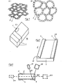
- FIG. 1 c which contains the structures of FIGS. 1 a, 1 b in their entire spatial extent.
- a metal oxide, a metal oxide hydrate or metal hydroxide which belongs to one of groups Ib, IIa, IIb, IIIa, IIIb, IVa, IVb, Va, Vb, VIa, VIb, VIIb, VIII of the periodic table or the lanthanoids or actinides, or a mixture, serves as the starting material these oxides, hydroxides or hydrated oxides. The selection is made according to the point of view for which gases the sensor elements 5 are to be used.
- a colloidal metal oxide, metal oxide hydrate or metal hydroxide solution is made. Since the production of colloidal solutions is known, only the following are described Differences to the known explained.
- a metal salt or mixture of metal salts is dissolved in water. By adding alkalis, for example NaOH, KOH, NH 4 OH etc., the metal oxide, the metal oxide hydrate or the metal hydroxide is precipitated. The precipitate is washed with water and dissolved again as a colloid by a peptizing agent, for example HCl, CH 3 COOH, NaOH, KOH, NH 4 OH.
- This colloidal solution is purified by dialysis.
- metal alkoxides of the Me (OR) x type can also be used.
- the symbol Me means the metal and the symbol OR an alcohol residue. If these metal alkoxides are dissolved in an organic solvent, for example in ethanol, isopropanol, acetone, etc., instead of in water, a colloidal metal hydroxide solution or a colloidal metal oxide or a metal oxide hydrate solution can result from the addition of water.
- an organic solvent for example in ethanol, isopropanol, acetone, etc.
- a colloidal metal hydroxide solution or a colloidal metal oxide or a metal oxide hydrate solution can result from the addition of water.
- a slightly yellowish plate of SnO 2 xerogel with a porosity (interstices 3) of 48% by volume and a size of the grains 2 in the range from 1 nm to 80 nm is obtained.
- the choice of the drying rate and the temperature gradient determines the porosity and the grain size, which is no longer changed, for example by the subsequent processing operations. Therefore, the optimal size of the grains 2 and the interspaces 3 for the gas detection can be correctly selected from the beginning without fear of unwanted changes.
- the gel plate 16 shown in FIG. 1c has such a high stability or strength that it can now be processed using the methods known in semiconductor technology.
- the gel plate 16 is ground, polished, steamed with electrodes and cut or sawn into pieces.
- two rectangular and one elliptical sensor element are shown in FIG. 1c.
- the shape of a sensor element is chosen so that it has the optimal shape for the intended gas detection.
- the sensor elements can have square, rectangular, circular, elliptical, etc. cross sections and a pyramid, Represent sphere, cylinder, cone, prism, etc. This design depends on the gas sensor in which the sensor element is to be installed and the flow velocities for gas detection.
- the sensor elements separated from the gel plate 16 are vaporized with electrodes 4 if they are provided for gas detection by means of the electrical properties of the material 1. This will be described in more detail later.
- the aqueous 0.1 molar solution of colloidal Ti0 2 is now poured into a mold. This solution is allowed to dry slowly for 4 days at room temperature and at normal pressure.
- a gel is obtained that has taken the form of a plate, for example.
- the gel plate is placed in repeatedly renewed methanol in a further process step for several weeks and thus transferred to an alkogel plate. This process is carried out at room temperature and at normal pressure.
- the methanol-impregnated alkogel plate is then brought to a pressure and temperature which are supercritical for methanol, and is left there for one hour. Then the pressure is reduced to normal pressure and then the temperature to room temperature.
- the time of drying of the colloidal solution and the size of the temperature and the pressure determine the porosity and the grain size.
- the subsequent process steps no longer change the porosity and the grain size. Therefore, the optimal size for the gas detection of the grains 2 and the interspaces 3 can be chosen correctly from the beginning without having to fear that they will change unintentionally.
- the gel plate 16 shown in FIG. 1c has a high size despite its large porosity and small grain size Stability or strength, so that the plate can be processed using the usual methods in semiconductor technology.
- the gel plate 16 is ground, polished and cut or sawn into pieces according to FIG. 1c.
- the sensor elements 5, in which their electrical conductivity is used for gas detection, are vaporized with electrodes 4.
- the sensor elements, in which their optical properties are used for gas detection, do not receive any electrodes.
- the organic solvent for example methanol
- the colloidal Ti0 2 solution it is also possible to add the organic solvent, for example methanol, to the colloidal Ti0 2 solution.
- the solution is then poured into the mold and formed into the gel plate 16 as described.
- the gel plate is only brought up to supercritical temperature and supercritical pressure for the methanol and left there for half an hour. Then the pressure is first reduced to normal pressure and then the temperature to room temperature. The subsequent processing of the gel plate into sensor elements has remained the same.
- Preferred metal oxide gels consist of the oxides of Ti, Zn, Sn, La, Cu, Cr, Ni, Al, Fe, In, Bi, Mn, V, W, Zr and from their mixtures with each other.
- Preferred catalysts are metals Ag, Au, Pt, Pd, Rh, Ir, Ru, Os, Cu, Cr, Ni, Fe, Co, La, Ce, Mn and their oxides. These catalysts can already be contained in the colloidal solution in a suitable form from the start.
- the plate 16 made of metal oxide xerogel or metal oxide aerogel can also be introduced subsequently by soaking the plate 16 made of metal oxide xerogel or metal oxide aerogel with the solution of one or more organic metal salts or metal complexes and bringing it to a temperature which is preferably around 700 ° C., preferably around 500 ° C. or 300 ° C. is higher than the later operating temperature at which the sensor element 5 is to be operated.
- the metal salts or metal complexes decompose during this heating process.
- the catalyst is then in the form of only metal oxide or metal particles in the plate 16 without ionic impurities.
- FIG. 2 shows a rectangular sensor element 5 with the spatial dimensions 1mm x 2mm x 0.5mm, which was cut out of the large gel plate 16.
- the electrodes 4 are deposited as a thin gold layer (approx. 2 pm) on the surface and connected with thin wires 11, which have a diameter of approx. 30 pm and therefore have a small heat dissipation.
- the sensor element 5 is brought to its operating temperature, which can be in the range between room temperature up to 450 ° C.
- the material 1 of the sensor element 5 principally detects all occurring oxidizing and reducing gases.
- material 1 has different responses for different gases, its responsiveness for the gases or ranges of gas compositions to be expected is optimized in such a way that the cheapest metal oxide or metal hydroxide or mixtures thereof with or without catalyst and the cheapest operating temperature are selected.
- the operating temperature can be determined by the heater 8 (see FIGS. 6-10) or by the environment temperature (see FIGS. 2-5) can be set and kept constant.
- the electrical conductivity changes when a gas penetrates into the material 1. or sweeps its surface. The change in the electrical conductivity is measured between the electrodes 4. Therefore, wires 11 are connected to an evaluation device which measures the change in the conductance and indicates the gas and the gas concentration and initiates an alarm or corresponding countermeasures, for example venting and venting.
- This evaluation device is not the subject of the present invention and is therefore neither drawn nor described.
- the material 1 is drawn in a rectangular shape.
- the two electrodes 4 are arranged as surface electrodes on the two opposite sides.
- the wires 11 lead from the electrodes to an evaluation device, not shown, which measures the electrical conductivity between the electrodes 4 and detects the gas and its concentrations on the basis of the change in the electrical conductivity, and gives an alarm if the concentration limit is exceeded or takes appropriate countermeasures.
- the spatial dimensions of material 1 are 1 mm x 1.5 mm x 0.5 mm.
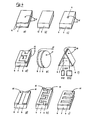
- FIG. 4b shows a rectangular sensor element without an electrode.
- a reflective layer 15 with a thickness of 3 ⁇ m is arranged on the lower side of the material 1.
- the sensorele ment is intended for the optical reflection measurement method and has the spatial dimensions of 0.1mm x 0.1mm x 0.02mm.
- FIG. 4c shows a rectangular sensor element with a sheet-like electrode on the lower side of the material 1 and a punctiform electrode on the upper side.
- the electrodes are provided with wires 11.
- the sensor element is intended for the electrical conductivity measurement method.
- Figure 4d shows a rectangular sensor element with sheet-like electrodes 4.
- the one electrode covers the entire lower surface of the material 1.
- the other electrode is designed in a certain pattern, e.g. Meander pattern, and covers only part of the opposite surface of the material 1.
- the electrodes 4 are provided with wires 11.
- the sensor element is intended for the electrical conductivity measurement method and has the spatial dimensions of 10mm x 5 ⁇ m x 1mn.
- FIG. 4e shows a cylindrical sensor element 5, the electrodes 4 of which are attached to the two opposite surfaces of the material 1 and are connected via wires 11 to an evaluation device (not shown).
- the sensor element is used for the electrical conductivity measurement method and has a diameter of 2mm.
- FIG. 4 f shows a prismatic sensor element.
- the two electrodes 4 are arranged on the two surfaces of the material 1 converging at an acute angle and are electrically insulated from one another at the tip of the sensor element.
- the wires 11 connect the electrodes 4 to the evaluation device (not shown).
- the sensor element is used for the electrical conductivity measurement method. Since the two electrodes 4 consist of a gold layer, their inner surfaces are mirror surfaces on which a beam 202, which is generated by a radiation source 212, is reflected and reaches a radiation receiver 222, which forwards the signal to an evaluation device (not shown).
- the device is intended for the optical measurement method.
- the sensor element can therefore be used for both measurement methods and also optionally for one or the other measurement method. This can be done e.g.
- the signals in the evaluation device are selected accordingly.
- the beam 202 is reflected twice and covers a large distance through the material 1. This gives the advantage that, despite the small spatial mass of the sensor element, there is a large distance for measuring the optical property and thus a high sensitivity.
- FIG. 4g shows the material 1 of the sensor element 5 with two electrodes 4, which are connected via the wires 11 to the evaluation device (not shown).
- the sensor element of this figure can e.g. be glued to a heating surface. This heating surface would be arranged on the lower side of the sensor element.
- FIG. 4h shows a pattern of the electrodes 4 arranged on one side of the material 1.
- the electrodes have the connecting wires 11.
- FIG. 4i shows a different pattern of the electrode 4 on the upper side of the material 1 than on the lower side.
- FIG. 4k shows an electrode 4 with a further pattern on the upper side and a plate-shaped electrode 4 on the lower side.
- FIG. 41 shows a plate-shaped electrode 4 on the lower side of the material 1.
- An electrode 4 with a specific pattern is provided on the opposite side.
- FIG. 4 m shows a plate-shaped electrode 4 on the lower side and a plate-shaped electrode 4 on the upper side of the material 1.
- the upper electrode 4 has holes so that the air with the gaseous impurities that are to be detected is directed to the upper side of the material 1 of the sensor element can be blown.
- the holes in the electrode are so big that there is enough air on the can reach the upper surface of the material 1 of the sensor element.
- FIG. 4n shows the material which has an electrode 4 on each of its two side ends.
- This electrode arrangement is expedient if the material 1 of the sensor element is to be placed on a heating layer 8. This will be explained in more detail later in connection with FIGS. 6, 7, 8 and 9.
- FIG. 4o shows the two electrodes 4 on the lower side of the material 1. This is a similar construction as will be described later in connection with FIG. 5.
- FIG. 4p shows a special pattern of two electrodes 4, which are arranged on one side, namely the lower, of the material 1.
- the sensor element of this figure is intended to provide a heating layer 8 on the side which has electrodes and the element is glued onto the insulating layer 7 via the electrodes 4. This will be discussed in more detail later in conjunction with FIGS. 6 , 7, 8 and 9.
- the material 1 of the sensor element 5 is enclosed gas-tight on all sides with the exception of the upper surface.
- the gas mixture to be detected must therefore diffuse through the material 1 from above. Since some of the easily oxidizable gases already burn on the top, these preferably result in a change in conductivity at the upper electrodes 4.
- the temperature is also lower at the top than at the bottom where the heater is installed.
- the gases which can only be oxidized at higher temperatures diffuse into the area of the lower electrodes 4 and result in a change in the electrical conductivity. This achieves a certain specificity of the sensor for different types of gas.
- the sensor element 5 contains a perforated one upper electrode 4 and two electrodes provided on the lower side. With this sensor element, the resistance is measured from the upper to the two lower electrodes.
- This sensor element is heated, for example, only on the left side and is therefore at a higher temperature than on the right. If the air to be examined with the gaseous impurities flows from right to left, the easily oxidizable gases are first oxidized on the right side and result in large changes in the electrical conductivity on the right. On the left side, the gases that can be oxidized at higher temperatures will generate the corresponding electrical signals. This enables a gas mixture to be divided into its individual components.
- the number of the lower electrodes 4 need not be two, but can be 5.10 or more.
- the entire sensor element can have a length of up to 2 cm.
- the depth is about 2mm.
- the height is about 1mm.
- the upper electrode 4 does not have to be perforated directly. It can simply be designed to be highly gas permeable. This means that the electrode can also be porous.
- the envelope 14 of the material 1 is gas impermeable.
- the sensor element 5 contains a continuous electrode on its lower surface, a perforated or highly porous electrode 4 in the middle and at the top.
- the material 1 which, however, has a different chemical composition at the bottom than that at the top. The two materials are therefore differently sensitive to different gases.
- FIGS. 2, 3, 4 a-s can be assembled to single gas sensors 6 (FIGS. 5, 6) or to multiple gas sensors 6 (FIGS. 7, 8, 9, 10) with or without heating 8.
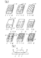
- FIG. 5 shows a gas sensor 6, which consists of the sensor element 5 and an electrically insulating layer 7. This layer 7 serves to isolate the two electrodes 4 and is approximately 0.02 mm thick.
- the gas sensor is attached to the location to be monitored and the wires 11 are connected to an evaluation device, the gas sensor is ready for operation. It is used for the electrical conductivity measurement method.
- Material 1 has the ambient temperature.
- the material 1 is shown rectangular in FIG. It can have any other shape as described in connection with the other figures.
- a heated gas sensor for the electrical conductivity measurement method is shown in FIG. 6.
- the electrodes 4 are attached to a surface of the material 1 and are covered by the electrical insulation layer 7.
- the heater (8) is provided between the insulation layer 7 and an electrically insulating substrate 9 and, in this exemplary embodiment, consists of heating wires which are drawn with dashed lines. This entire arrangement is attached to a thermally and electrically insulating substrate 10.
- the Gas sensor 6 is attached to the location to be monitored and attached there with its substrate 10.
- the wires 11 connect the electrodes 4 to the evaluation device, not shown.
- the heating layer 8 is connected to a power source, not shown.
- a heating control ensures that the desired operating temperature, which can range from room temperature to 450 ° C, is set and kept constant.
- the spatial mass of the gas sensor 6 in FIG. 6 is 5 mm in height, 3 mm in width and 3 mm in length. The gas sensor is suitable for installation in the most difficult places.
- Each of the sensor elements 5 or individual sensors 6 described so far are optimally set for the detection of a gas. As already described, this is done by appropriate choice of material 1, the measurement method and the operating temperature. If a number of different gases are to be detected at one location, multiple gas sensors of FIGS. 7-12 are used.
- FIG. 7 shows the top view of a plurality of sensor elements which are arranged on the electrical insulation layer 7.
- the material 1 and the electrodes 4 are arranged as shown in a side view in FIG. 5.
- the wires 11 of each pair of electrodes 4 are guided to contact points 12, which are fixed on the insulation layer 7 are. As already mentioned, the wires have a very small heat dissipation.
- the electrical contact points 12 are connected via lines to an evaluation device, which is not shown in FIG. 7.
- the heating layer 8 and the thermally and electrically insulating layer 9 according to FIG. 6 are arranged under the electrical insulation layer 7. According to FIG. 7, all sensor elements are heated to the same operating temperature by the heating layer 8.
- Each sensor element can be heated to a different operating temperature.
- a separate heating layer 8 is provided for each sensor element, the heating layers and the areas of the sensor elements being thermally insulated from one another.
- each sensor element to a certain gas is expediently set, so that four different gases and their concentrations can be detected with the multiple gas sensor of FIG.
- more sensor elements can be arranged on the insulation layer 7.
- FIG. 8 shows a top view of another type of multiple gas sensor.
- a larger number of gas sensors of FIGS. 2, 4a, 4d, 5 and 6 are arranged on the thermally and electrically insulating substrate 10. Because of the better overview, only the sensors are shown in the upper row of FIG. 8. In the upper row on the right, material 1 and the associated electrodes 4 for two sensor elements are attached to the electrical insulation layer 7 (FIG. 5). A heating layer is not provided because these sensor elements be operated at ambient temperature. Therefore, the layer 7 is glued directly to the substrate 10. The wires 11 connect the electrodes 4 to the electrical contact points 12, which are attached to the substrate 10. The electrical connections go from the contact points to an evaluation device. Two sensor elements of FIGS.
- the wires 11 connect the electrodes 4 to the contact points 12 fastened on the thermally and electrically insulating substrate 10. In the sensor element constructed according to FIG. 4a, the lower electrode is not visible in FIG. Connections to the evaluation device go from the contact points.
- Two sensor elements according to FIGS. 4a and 4d are arranged in the upper row on the left. Each sensor element has its own heating layer 8 and therefore also the separate insulation layer 7 and the electrically insulating substrate 9.
- each sensor element is brought to a different operating temperature.
- the wires 11 connect the electrodes 4 to the electrical contact points 12 in the same way as in the previously described sensor elements. This is not shown now, since Figure 8 should not lose its clear presentation.
- a heating layer 8 can optionally be provided. With the multiple gas sensor of Figure 8, twelve different gases can be detected. Of course, the number can be arbitrary be raised.
- FIG. 9 shows another multiple gas sensor.
- a plurality of sensor elements in the form of a cube have a hole in the middle which passes through all sensor elements 5 and forms a tube. The air to be examined is guided in this tube and exits again at the end of the tube. The direction of flow is indicated by arrows.
- the sensor elements change their electrical conductivity when the gas passes by their surface for which their response behavior has been optimized.
- Each sensor element has its electrodes 4 which are arranged in such a way that they do not influence one another in the compact arrangement of the sensor elements.
- the wires 11 ensure the electrical connection of the electrodes 4 to the contact points 12, which are attached to the electrical insulation layer 7 and are connected to an evaluation device.
- the arrangement mentioned is glued onto the thermally and electrically insulating substrate 10. With the multiple gas sensor of FIG. 9, more than just four gases can be detected if more sensors are arranged accordingly.
- the sensors can also be operated using the optical measurement method and can be electrically isolated from one another by thin insulating layers.
- the entire block of sensor elements is enclosed by a gas-tight envelope, not shown in FIG. 9, with the exception of two openings at the two ends.
- This arrangement makes it possible to break down a gas mixture into its components and the individual components on separate sensor elements by changing the resistance of the same to prove.
- the electrodes in FIG. 9 do not necessarily have to be attached to the outside, but can also be provided between the individual sensor elements.
- the gas sensor in FIG. 9 expediently has a lower temperature at one end, for example at the left, than at the other end, ie at the right.
- the gas flow is then also expedient from left to right in the direction of the arrow.
- Gases that already burn at low temperatures are then preferably burned on the left (first sensor element) and there result a major change in the electrical signals for the conductivity. Gases that only burn at higher temperatures will only burn at the second sensor element, gases that burn at even higher temperatures only at the third sensor element, etc. This enables the gases to be detected much more selectively.
- the sensor elements consist of a highly porous metal oxide gel, for example an airgel, the center hole is not even necessary. The embodiment in FIG. 9 should therefore also refer to such cases.
- FIG. 10 shows a multiple gas sensor which consists of several pyramid-shaped sensor elements.
- the electrodes 4 are connected via wires 11 to the electrical contact points 12 fastened to the thermally and electrically insulating substrate 10, which are connected to an evaluation device via connecting lines.
- the electrodes are insulated so that they only come into contact with the assigned material 1 and not with the material 1 of the other sensor have element.
- the outer walls of the sensor elements are partially provided with a gas-tight layer 14. Therefore, only the surfaces of the sensor elements lying on top are gas-active.
- the sensor elements are attached to the electrical insulation layer 7, which is connected to the heating layer 8 and the electrically insulating substrate. The entire arrangement is attached to the thermally and electrically insulating substrate 10.
- each sensor element is intended for a specific gas. There is the possibility, for example, that the uppermost sensor element is operated at ambient temperature. Then the sensor element should be thermally insulated from the other sensor elements. Furthermore, more sensor elements can be used for the multiple gas sensor of FIG. 10 than only those shown.
- the contact points 12 in FIGS. 7-10 do not necessarily have to be on the electrically insulating layer 7, they can also lie outside of this layer.
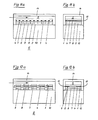
- FIG. 11a shows a longitudinal section and FIG. 11b shows a cross section through a multiple gas sensor 6, which contains a sensor element 5, which consists of the material 1 and carries a large number of electrodes 4 on its underside.
- the sensor element 5 is attached to the heating layers 8 by an electrically insulating layer 7.
- the heating layer 8 on the far left in FIG. 11a heats the zone of the sensor element 5 located above it, e.g. to 80 ° C.
- the next heating layer 8 on the right heats the zone of the sensor element 5 above e.g. 90 ° C etc.
- the sensor element 5 therefore has an increasing temperature from left to right.
- the individual heating layers 8 are attached to a heat-insulating substrate 10 by an electrically insulating layer 9.
- FIG. 11 shows a gas-tight layer 14 which surrounds the layers 7, 8 and 9 and the sensor element 5 in such a way that a free space remains above the sensor element 5.
- the air to be examined is passed through this free space in a laminar flow from left to right, which is indicated by the arrow in FIG. 11a.
- This laminar air flow can be generated by a pump (not shown in FIG. 11) or also by placing the entire gas sensor 6 vertically in FIG. 11, the heating layer 8 with the lowest temperature being at the bottom. Due to the chimney effect, the laminar air flow then sets itself up.
- FIG. 12a shows a longitudinal section and FIG. 12b shows a cross section through another multiple gas sensor 6, which contains several sensor elements 5, which are made of different mate rial 1 exist and each contain two electrodes 4.
- These sensor elements 5 are brought to individual temperatures by separate heating layers 8, which are located between electrically insulating layers 7 and 9 and are fastened on a heat-insulating substrate 10.
- the sensor element 5 on the far left has a temperature of only 65 ° C.
- the next sensor element on the right has a temperature of 80 ° C.
- the next one has a temperature of 100 ° C etc.
- the sensor element on the far right has a temperature of 400 ° C.
- FIG. 12 also shows a gas-tight layer 14 which surrounds the layers 7, 8 and 9 and the sensor elements 5 in such a way that a free space above the sensor elements 5 remains open.
- the air to be examined is passed through this free space in a laminar flow from left to right, which is indicated by an arrow in FIG. 12a.
- this laminar air flow can either be generated by an external pump, not shown in FIG. 12, or by the chimney effect which arises when the entire gas sensor 6 is placed vertically, the sensor element having the lowest temperature is at the bottom.
- the lead wires 11 lead in the figure 12b through the gas-tight layer 14 to the outside.
- the material 1 of this sensor element 5 is also selected (it contains, for example, a special catalyst) such that these easily oxidizable substances can preferably burn on this sensor element. Somewhat more difficult to oxidize substances are burned on the second sensor element (based on the air flow), whereby this oxidation is due to an optimal operating temperature is higher than that of the preceding sensor element, and is strongly promoted by a suitable chemical composition of the material 1.
- the chemical composition of the materials 1 of the sensor elements 5 is also optimally selected, the gaseous impurities in the air to be detected can be detected extremely selectively.
- a suitable mathematical combination of the signals from the individual sensor elements 5 can again increase the selectivity of this gas sensor 6 very strongly.
Landscapes
- Chemical & Material Sciences (AREA)
- Analytical Chemistry (AREA)
- General Health & Medical Sciences (AREA)
- Physics & Mathematics (AREA)
- Health & Medical Sciences (AREA)
- Life Sciences & Earth Sciences (AREA)
- Chemical Kinetics & Catalysis (AREA)
- Biochemistry (AREA)
- Electrochemistry (AREA)
- General Physics & Mathematics (AREA)
- Immunology (AREA)
- Pathology (AREA)
- Investigating Or Analyzing Materials By The Use Of Fluid Adsorption Or Reactions (AREA)
- Sampling And Sample Adjustment (AREA)
- Investigating Or Analysing Materials By Optical Means (AREA)
Applications Claiming Priority (2)
| Application Number | Priority Date | Filing Date | Title |
|---|---|---|---|
| CH4737/83 | 1983-08-30 | ||
| CH473783A CH667331A5 (de) | 1983-08-30 | 1983-08-30 | Vorrichtung zum nachweis von gasfoermigen verunreinigungen in luft mittels eines gassensors. |
Publications (2)
| Publication Number | Publication Date |
|---|---|
| EP0141090A2 true EP0141090A2 (fr) | 1985-05-15 |
| EP0141090A3 EP0141090A3 (fr) | 1988-06-29 |
Family
ID=4281620
Family Applications (1)
| Application Number | Title | Priority Date | Filing Date |
|---|---|---|---|
| EP84109653A Withdrawn EP0141090A3 (fr) | 1983-08-30 | 1984-08-14 | Appareil pour la détection d'impuretés gazeuses dans l'air à l'aide de capteurs de gaz |
Country Status (4)
| Country | Link |
|---|---|
| EP (1) | EP0141090A3 (fr) |
| JP (1) | JPS6071941A (fr) |
| CH (1) | CH667331A5 (fr) |
| ES (1) | ES8606648A1 (fr) |
Cited By (10)
| Publication number | Priority date | Publication date | Assignee | Title |
|---|---|---|---|---|
| EP0238081A1 (fr) * | 1986-03-19 | 1987-09-23 | NGK Spark Plug Co. Ltd. | Elément sensible aux gaz à couches gros |
| EP0226570A3 (fr) * | 1985-12-09 | 1989-03-15 | OttoSensors Corporation | Dispositif de mesure avec connexion de tubes et son procédé de fabrication |
| USRE33980E (en) * | 1986-03-19 | 1992-06-30 | Ngk Spark Plug Co., Ltd. | Thick-film gas-sensitive element |
| EP0527258A1 (fr) * | 1991-08-14 | 1993-02-17 | Siemens Aktiengesellschaft | Matrice de détecteurs de gaz pour la détection des composants individuels dans un mélange de gaz |
| EP0527259A1 (fr) * | 1991-08-14 | 1993-02-17 | Siemens Aktiengesellschaft | Détecteur de gaz avec de l'oxyde de gallium sémiconducteur |
| EP0608483A1 (fr) * | 1993-01-28 | 1994-08-03 | Siemens Aktiengesellschaft | Procédé et dispositif capteur de gaz à semi-conducteur pour la détection de risques d'incendie ou d'explosion |
| US5427740A (en) * | 1991-04-05 | 1995-06-27 | British Gas Plc | Tin oxide gas sensors |
| CN110488837A (zh) * | 2019-08-28 | 2019-11-22 | 哈尔滨工业大学 | 一种气体源伪源确认方法 |
| CN111272714A (zh) * | 2020-03-03 | 2020-06-12 | 电子科技大学中山学院 | 一种光学谐振腔原理的金属氧化物气体传感器 |
| CN117890441A (zh) * | 2024-03-18 | 2024-04-16 | 北京中科海芯科技有限公司 | 一种气体传感器及其制作方法 |
Families Citing this family (1)
| Publication number | Priority date | Publication date | Assignee | Title |
|---|---|---|---|---|
| JP4807561B2 (ja) * | 2005-11-22 | 2011-11-02 | 国立大学法人九州大学 | ガスセンサ用金属酸化物半導体材料の製造方法 |
Family Cites Families (7)
| Publication number | Priority date | Publication date | Assignee | Title |
|---|---|---|---|---|
| US3663176A (en) * | 1969-07-24 | 1972-05-16 | Phillips Petroleum Co | Colorimetric oxygen detectors |
| JPS5023317B1 (fr) * | 1969-12-19 | 1975-08-06 | ||
| DE2434933C2 (de) * | 1971-11-15 | 1984-12-20 | Ford-Werke AG, 5000 Köln | Sensor einer Meßeinrichtung für den Sauerstoffteildruck der Auspuffgase einer Brennkraftmaschine eines Kraftfahrzeuges |
| JPS5039998A (fr) * | 1973-08-14 | 1975-04-12 | ||
| US3920402A (en) * | 1974-05-16 | 1975-11-18 | Nikolai Gavrilovich Afanasiev | Photocolorimetric gas analyzer |
| DE2821267A1 (de) * | 1978-05-16 | 1979-11-22 | Siemens Ag | Gassensoren und verfahren zu ihrer herstellung |
| US4286378A (en) * | 1979-03-09 | 1981-09-01 | General Motors Corporation | Process for producing a body of sintered TiO2 for resistive gas sensor |
-
1983
- 1983-08-30 CH CH473783A patent/CH667331A5/de not_active IP Right Cessation
-
1984
- 1984-08-14 EP EP84109653A patent/EP0141090A3/fr not_active Withdrawn
- 1984-08-28 ES ES535775A patent/ES8606648A1/es not_active Expired
- 1984-08-29 JP JP17854084A patent/JPS6071941A/ja active Pending
Cited By (13)
| Publication number | Priority date | Publication date | Assignee | Title |
|---|---|---|---|---|
| EP0226570A3 (fr) * | 1985-12-09 | 1989-03-15 | OttoSensors Corporation | Dispositif de mesure avec connexion de tubes et son procédé de fabrication |
| US4857275A (en) * | 1986-03-19 | 1989-08-15 | Ngk Spark Plug Co., Ltd. | Thick-film gas-sensitive element |
| USRE33980E (en) * | 1986-03-19 | 1992-06-30 | Ngk Spark Plug Co., Ltd. | Thick-film gas-sensitive element |
| EP0238081A1 (fr) * | 1986-03-19 | 1987-09-23 | NGK Spark Plug Co. Ltd. | Elément sensible aux gaz à couches gros |
| US5427740A (en) * | 1991-04-05 | 1995-06-27 | British Gas Plc | Tin oxide gas sensors |
| US6235243B1 (en) | 1991-08-14 | 2001-05-22 | Siemens Aktiengesellschaft | Gas sensor array for detecting individual gas constituents in a gas mixture |
| EP0527258A1 (fr) * | 1991-08-14 | 1993-02-17 | Siemens Aktiengesellschaft | Matrice de détecteurs de gaz pour la détection des composants individuels dans un mélange de gaz |
| EP0527259A1 (fr) * | 1991-08-14 | 1993-02-17 | Siemens Aktiengesellschaft | Détecteur de gaz avec de l'oxyde de gallium sémiconducteur |
| EP0608483A1 (fr) * | 1993-01-28 | 1994-08-03 | Siemens Aktiengesellschaft | Procédé et dispositif capteur de gaz à semi-conducteur pour la détection de risques d'incendie ou d'explosion |
| CN110488837A (zh) * | 2019-08-28 | 2019-11-22 | 哈尔滨工业大学 | 一种气体源伪源确认方法 |
| CN110488837B (zh) * | 2019-08-28 | 2022-07-01 | 哈尔滨工业大学 | 一种气体源伪源确认方法 |
| CN111272714A (zh) * | 2020-03-03 | 2020-06-12 | 电子科技大学中山学院 | 一种光学谐振腔原理的金属氧化物气体传感器 |
| CN117890441A (zh) * | 2024-03-18 | 2024-04-16 | 北京中科海芯科技有限公司 | 一种气体传感器及其制作方法 |
Also Published As
| Publication number | Publication date |
|---|---|
| ES535775A0 (es) | 1986-04-16 |
| EP0141090A3 (fr) | 1988-06-29 |
| ES8606648A1 (es) | 1986-04-16 |
| JPS6071941A (ja) | 1985-04-23 |
| CH667331A5 (de) | 1988-09-30 |
Similar Documents
| Publication | Publication Date | Title |
|---|---|---|
| DE69629040T2 (de) | Gassensor und verfahren zu dessen herstellung | |
| DE69418615T2 (de) | Katalytischer gassensor | |
| DE3783103T2 (de) | Elektrochemischer gassensor und verfahren zu seiner herstellung. | |
| DE69305341T2 (de) | Zusammensetzungen, verfahren und vorrichtung zur abscheidung von sauerstoff aus einer gasmischung | |
| CH665908A5 (de) | Vorrichtung zum selektiven detektieren der gasfoermigen bestandteile von gasgemischen in luft mittels eines gassensors. | |
| DE68917856T2 (de) | Sauerstoffsensorvorrichtung. | |
| DE2837118C2 (de) | Poröse Oxidelektroden für elektrochemische Hochtemperaturzellen | |
| EP0141033A2 (fr) | Procédé pour la fabrication de matériaux pour des capteurs de gaz | |
| DE2718907C2 (de) | Meßfühler zur Bestimmung des Sauerstoffgehalts in Abgasen | |
| EP0141090A2 (fr) | Appareil pour la détection d'impuretés gazeuses dans l'air à l'aide de capteurs de gaz | |
| DE3907312A1 (de) | Keramische widerstandsheizeinrichtung mit untereinander verbundenen waermeentwickelnden leitern und eine derartige heizeinrichtung verwendendes elektrochemisches element oder analysiergeraet | |
| EP0120203A1 (fr) | Dispositif pour la détection de polluants gazeux dans l'air au moyen d'un détecteur de gaz | |
| DE69933516T2 (de) | Kohlenmonoxidsensor, Verfahren zu dessen Herstellung und Verfahren zu dessen Verwendung | |
| EP2220482B1 (fr) | Détecteur de gaz à sélectivité améliorée | |
| DE4107812C2 (de) | Grüne Keramikplatte für eine poröse Schicht, elektrochemisches Element, bei dessen Herstellung die grüne Keramikplatte verwendet wird, und Verfahren zur Herstellung des Elements | |
| EP0952447A1 (fr) | Capteur de gaz et son utilisation de capteur de méthane et propane | |
| DE102016222021A1 (de) | Gassensor und herstellungsverfahren eines gassensors | |
| DE2908916C2 (de) | Widerstandsmeßfühler zur Erfassung des Sauerstoffgehaltes in Gasen, insbesondere in Abgasen von Verbrennungsmotoren und Verfahren zur Herstellung derselben | |
| DE2524597A1 (de) | Verfahren und vorrichtung zum aufspueren eines gases | |
| DE102010041763A1 (de) | Mikromechanisches Substrat | |
| EP0512500B1 (fr) | Capteur d'oxygène et son procédé de fabrication | |
| EP0859536A1 (fr) | Radiateur infra-rouge et son application | |
| DE68912793T2 (de) | Sauerstoffsensor und Verfahren zu seiner Herstellung. | |
| DE69320777T2 (de) | Festelektrolytische Gassensorvorrichtung | |
| DE69120948T2 (de) | Gasfühler |
Legal Events
| Date | Code | Title | Description |
|---|---|---|---|
| PUAI | Public reference made under article 153(3) epc to a published international application that has entered the european phase |
Free format text: ORIGINAL CODE: 0009012 |
|
| 17P | Request for examination filed |
Effective date: 19840814 |
|
| AK | Designated contracting states |
Designated state(s): BE CH DE FR GB IT LI |
|
| PUAL | Search report despatched |
Free format text: ORIGINAL CODE: 0009013 |
|
| AK | Designated contracting states |
Kind code of ref document: A3 Designated state(s): BE CH DE FR GB IT LI |
|
| STAA | Information on the status of an ep patent application or granted ep patent |
Free format text: STATUS: THE APPLICATION IS DEEMED TO BE WITHDRAWN |
|
| 18D | Application deemed to be withdrawn |
Effective date: 19881230 |
|
| RIN1 | Information on inventor provided before grant (corrected) |
Inventor name: FORSTER, MARTIN, DR. SC. NAT. |