EP0141120A1 - Dispositif pour le traitement mécanique de la surface inférieure d'un bateau en cale - Google Patents
Dispositif pour le traitement mécanique de la surface inférieure d'un bateau en cale Download PDFInfo
- Publication number
- EP0141120A1 EP0141120A1 EP84110181A EP84110181A EP0141120A1 EP 0141120 A1 EP0141120 A1 EP 0141120A1 EP 84110181 A EP84110181 A EP 84110181A EP 84110181 A EP84110181 A EP 84110181A EP 0141120 A1 EP0141120 A1 EP 0141120A1
- Authority
- EP
- European Patent Office
- Prior art keywords
- underbody
- support arms
- implement
- carrier
- working
- Prior art date
- Legal status (The legal status is an assumption and is not a legal conclusion. Google has not performed a legal analysis and makes no representation as to the accuracy of the status listed.)
- Granted
Links
Images



Classifications
-
- B—PERFORMING OPERATIONS; TRANSPORTING
- B63—SHIPS OR OTHER WATERBORNE VESSELS; RELATED EQUIPMENT
- B63B—SHIPS OR OTHER WATERBORNE VESSELS; EQUIPMENT FOR SHIPPING
- B63B59/00—Hull protection specially adapted for vessels; Cleaning devices specially adapted for vessels
- B63B59/06—Cleaning devices for hulls
-
- B—PERFORMING OPERATIONS; TRANSPORTING
- B24—GRINDING; POLISHING
- B24C—ABRASIVE OR RELATED BLASTING WITH PARTICULATE MATERIAL
- B24C3/00—Abrasive blasting machines or devices; Plants
- B24C3/02—Abrasive blasting machines or devices; Plants characterised by the arrangement of the component assemblies with respect to each other
- B24C3/06—Abrasive blasting machines or devices; Plants characterised by the arrangement of the component assemblies with respect to each other movable; portable
Definitions
- the invention is used in shipbuilding both in new buildings and in the repair sector.
- the known prior art has a large number of devices which are used for mechanized cleaning and rust removal from the underbody of ships.
- a mobile device which can be moved on the dock floor under the hull resting on pallings.
- a lever mechanism is arranged on the vehicle, with which a disk brush rotating about a vertical axis is moved against the surface to be cleaned.
- the disc brush removes the vegetation as well as paint residues and loose rust from the underbody.
- the deficiency of this device is that the surface it processes does not have the quality parameters required for preservation by means of paint application.
- centrifugal blasting device with which an almost rust-free underbody surface is achieved and the best conditions are created for a subsequent preservation.
- a centrifugal blasting device is described in US Pat. No. 4,092,942.
- This device consists of the combination of an implement carrier designed as a caterpillar vehicle with a centrifugal jet unit.
- a pivotable support arm pair is arranged on the implement carrier at horizontal-axis articulation points, at the end of which the centrifugal jet unit is mounted.
- the centrifugal jet unit swings around an axis parallel to the pivot axis of the pair of support arms. This ensures that the centrifugal jet unit is directed with its outlet opening to the processing surface.
- the pair of support arms is pivoted about the said axis by hydraulic cylinders and the centrifugal jet unit is pressed against the underbody of the ship.
- the centrifugal blasting unit has a closed blasting medium circuit, from which the cut off dirt and dust particles are filtered out and the prepared blasting medium is fed to the centrifugal wheel via suitable conveying devices.
- the main disadvantage of the described mobile centrifugal blasting device arises from its exclusive suitability for derusting the ship's underbody. Especially on ships that are docked after a long period of use to renew the paint, the outer skin has a strong vegetation, the removal of which by the centrifugal jet unit leads to its blockage and thus to inoperability.
- the complex processing of the underbody of ships takes place according to the currently known state of the art in the sub-complexes "cleaning” and "rust removal".
- the device technology required for this is, as described, a technical solution tailored to the respective machining process.
- the respective working device with the associated mobile device carrier forms an inseparable functional unit which does not permit conversion to other types of machining.
- Another deficiency of the present state of the art is that, due to its mobility about the described pendulum axis, the working device received by the support arms of the device carrier deforms the sealing of the outlet opening of the centrifugal jet unit to the surface to be worked only in the plane or uniaxially deformed Area of the underbody.
- the multi-axis deformed areas, in particular of the fore and aft ship of this device technology, are therefore not accessible with the necessary effectiveness.
- the useful effect that occurs when the invention is used in comparison to known technical solutions consists in a sensible supplementation of the complex system of processing the sides of the ship by means of a corresponding technique for the underbody. This creates the conditions for cleaning, rust removal and preservation of the hull in the dock with minimal docking times.
- the object of the invention is to provide a device which can be maneuvered on the dock floor under the hull and which enables mechanized cleaning and / or rust removal of the underbody in its flat, limitedly inclined and deformed areas.
- a mobile device carrier which can optionally be equipped with one of several different tools for cleaning or rust removal.
- the working opening of the individual tools is directed towards the underbody of the ship to be worked.
- a quick-release gimbal mount which is inserted into the support arms articulated on the implement carrier, ensures that the implements can be exchanged quickly.
- the cardanic design of the recording ensures that the selected implement is level, limited and inclined adjusts deformed areas of the underbody with its working opening when it is pressed against the underbody by the pivot drive of the support arms with a defined minimum force. This minimum force is automatically set in connection with contact points that are arranged around the working opening and transmit a corresponding signal to the rotary drive when it is in contact with the underbody.
- the tools are the supply and Entsorgungsein - devices that are installed on the equipment rack, connected by detachable cables.
- the form of the cardanic mount embodied according to the invention is formed from a frame which horizontally surrounds the working device located in the normal position.
- the frame has two pivot axes that intersect at a right angle.
- the implement is arranged in one pivot axis by means of a pivot bearing, while in the other pivot axis the frame is received by the support arms of the implement carrier.
- the frame is therefore provided on both corresponding sides with pins which are inserted in bearing shells which are located at the free ends of the support arms.
- the bearing shells are designed so that the respective implement can be lifted out of the implement carrier by a suitable lifting device or inserted into it.
- the cardanic mount allows the implement to be largely adapted to the deformed areas of the sub-floor and thus effective and functional processing of the sub-floor.
- a feature of the invention relates to the implement for mechanized cleaning of the underbody by means of water jets.
- This tool consists of a horizontal nozzle holder, which has a large number of rectified water jet nozzles.
- the nozzle holder is set into an oscillating motion by a crank drive in order to achieve a uniform cleaning effect over the entire working width.
- the nozzle holder is supplied with high pressure water via a high pressure water hose to the respective tap of the stationary high-pressure water pipe, which is installed in the dock.
- the nozzle holder is surrounded by a housing that is open to the underbody.
- the brush seal surrounding the opening is in contact with the underbody.
- the brush seal removes the growth that has been loosened but not knocked off by the high pressure water.
- Another tool for mechanized cleaning of the underbody consists of a rotating brush system. This is made up of several staggered brush plates, each with its own drive and equipped with several cup brushes. This brush system is also housed in a housing which is open to the underbody, the opening being bordered by a brush seal. There are spacers on the housing with which the brush pressure on the underbody can be adjusted. A better adaptation of the brush system to the deformed areas of the underbody is achieved by the individual cup brushes being spring-loaded and pivotable in the axial direction. The pot brushes are also interchangeable. This ensures that the brushes are adapted to the type and strength of the contamination.
- the brush cleaning device has to remove vegetation, loose paint and rust from the sub-floor.
- the implement for mechanized rust removal from the sub-floor is a centrifugal blasting device with a closed abrasive circuit. Its main elements are the drive with the centrifugal wheel, the centrifugal wheel housing, the blasting chamber and wear plates.
- the blasting chamber has a working opening to the underbody which is surrounded by an elastic seal which prevents the blasting agent from escaping from the working device.
- the blasting medium accelerated by the centrifugal wheel and bouncing back from the surface to be processed is collected in a collecting container and fed back to the centrifugal wheel.
- Extraction nozzles that are connected to the device for disposal via lines in the equipment rack. The dust accumulating in the blasting chamber is sucked off through this in order to avoid clogging of the blasting medium circuit.
- the centrifugal blasting device is equipped with sensors which detect the lifting of the implement from the underbody and cause the blasting agent supply to the centrifugal wheel to be prevented. This reduces the loss of blasting media.
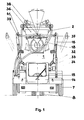
- the device for mechanized underbody processing of ships in the dock consists of a device carrier 1 and three tools, the water jet device 3 and the brush cleaning device 4 for cleaning and the centrifugal jet device 2 for rust removal.
- the device carrier 1 has the task of optionally picking up the tools, pressing them onto the underbody and guiding them there. Flat and slightly curved and deformed areas of the sub-floor can be processed without attaching the outer skin.
- the equipment carrier 1 is an autonomous vehicle with a diesel-hydraulic drive.
- the driving movements take place via the front wheels 7, which are individually hydraulically driven by a manual and an axle gear.
- the manual transmission also serves as a parking brake when both clutches are switched on.
- the device carrier 1 is braked while driving via the hydraulic system.
- the rear wheel 8 is designed as a twin wheel with a rigid axle body and a vertical steering axis 9.
- the hydrostatic energy metered by the steering unit in the driver's cab 14 is converted into mechanical kinetic energy above the rear wheel suspension by means of two hydraulic working cylinders 10.
- the working cylinders 10 are connected to one another by a roller chain 11, which rotates a sprocket 12 placed directly on the vertical steering axis 9 and thus actuates the steering.
- the internal front wheel drive is throttled to support the rear wheel steering. This is done via hydraulic directional valves, which are mechanically actuated by a pair of curves 13 arranged on the chain wheel 12 with a corresponding steering angle.
- the operating and command devices for the equipment carrier 1 and the working devices are located in the driver's cab 14 in side operating desks, easily accessible for the operator.
- the operator receives a seated workplace and is well protected in the driver's cab 14 against environmental influences.
- the arrangement of the driver's cab 14 in the center at the front ensures a good view of the implement.
- the all-round view is restricted by the overall height of the equipment rack 1.
- Getting in and out of the driver's cab 14 is only possible from the front through the entry flap.
- the steering wheel 15 with the steering unit must be folded out laterally.
- the operator is equipped with radio communication.
- the support arms 16 serve to quickly and securely hold the implement.
- the three devices mentioned can optionally be picked up and brought into the desired position.
- the support arms 16 are connected vertically between the lowest and the highest working position via the axis 32 to the frame structure of the equipment carrier 1.
- the support arms 16 are pivoted in this direction by means of hydraulic cylinders 33.
- the support arms 16 connect a cross member 34, which ensures the parallelism of the support arms 16 when swiveling out to the side.
- This pivoting movement is realized by a hydraulic cylinder 35 which engages on the one hand on the cross member 34 and on the other hand at the hinge point of the axis 32.
- a cardanic receptacle 36 which represents the link between the support arms 16 and the implement, ensures the attachment of the implement to the sub-floor even in areas deformed in several axes.
- the cardanic receptacle 36 consists of a frame 37 which horizontally surrounds the implement in the normal position and which has two pivot axes which intersect at a right angle. One pivot axis is realized via a pivot bearing 38, which connects the implement to the frame 37.
- pins 39 are arranged on the corresponding opposite sides of the frame, with which the frame 37 carrying the implement is suspended in the free ends of the support arms 16.
- the support arms 16 are therefore provided with bearing shells 40 which are open at the top and which allow the attachment or removal of the implement by means of a suitable lifting device facilitate.
- a securing element 41 prevents the implement from being unintentionally released from the implement carrier 1.
- the water jet device 3 works as a cleaning medium with high pressure water, which is provided with a pressure of approx. 320 bar in the dock.
- the equipment carrier 1 and thus the water jet device 3 are supplied with this high-pressure water via a stationary high-pressure water line with several connection points and a high-pressure water hose.
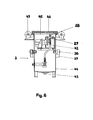
- the medium is distributed to a plurality of high-pressure water nozzles 28 arranged on a nozzle carrier 27 and sprayed against the underbody.
- the nozzle holder 27 is set into an oscillating movement transversely to the direction of travel of the device holder 1 by means of a crank mechanism 42, so that all areas of the working surface can be operated with a water jet.
- the water jet device 3 is surrounded by a housing 44, the working opening 45 of which is directed towards the underbody and bears against it with a brush seal 46.
- the brush seal 46 prevents the high-pressure water jet from escaping from the water jet device 3.
- the waste water and the cut off dirt particles are discharged through the drain opening 43 in the lower region of the housing 44.
- the rollers 47 arranged around the working opening 45 guide the water jet device 3 in connection with the cardanic receptacle 36 and with the vertical pivoting movement of the support arms 16 along the processing surface, the rollers 47 performing the function of the contact points for automatically setting the minimum force with which the water jet device 3 pressed against the underbody.
- the brush cleaning device 4 consists of four brush plates which are arranged next to each other in order to clean over the entire working width.
- Each brush plate 29 has its own drive 48 and is equipped with four cup brushes 30.
- the pot brushes 30 are resilient and pivotable in the axial direction.
- the pot brushes 30 can e.g. if the sub-floor is slightly dirty, replace it with plastic brushes.
- the brush system is surrounded by a housing 49, the working opening 50 of which is also directed towards the underbody. In this working device, too, the working opening 50 is surrounded by a brush seal 51, which prevents the cleaning residues that are produced from being thrown out of the working opening 50.
- the cleaning residues are collected in the dirt collecting box 31 arranged in the lower region of the brush cleaning device 4 and removed from time to time. Spacers 52 ensure the necessary brush pressure by automatically setting the minimum force.
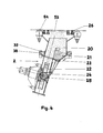
- the centrifugal blasting device 2 works with a closed blasting medium circuit.
- the wire grain 20 is located in a collecting container 21. After pressing the centrifugal blasting device 2 against the underbody and after the centrifugal wheel 22 is running, the abrasive pusher 23 is opened and the wire grain 20 slides through a funnel 24 to the pre-accelerator 25, which connects the wire grain 20 to it Spin wheel 22 releases.
- the centrifugal wheel 22 accelerates the wire grain 20 and hurls it against the underbody, from where it falls back into the collecting container 21.
- the wire grain 20 is prevented by a brush seal 26 from emerging from the centrifugal jet device 2.
- the circumferential amount of wire grains per unit of time can be metered by the position of the blasting medium slide 23.
- the centrifugal wheel parts are made of chilled cast iron and the blasting chamber is lined with low-abrasion material that can be replaced if necessary.
- Prerequisite for functionality of the centrifugal jet device 2 is the suction of the resulting dust, otherwise there is a risk that the gravity transport of the wire grain 20 clogs.
- the blasting chamber of the centrifugal blasting device 2 is connected to corresponding disposal devices which are arranged on the device carrier 1.
- the dust generated during rust removal consisting of the smallest rust, metal, vegetation, dirt and paint particles, is sucked out of the blasting chamber of the centrifugal blasting device 2 by means of a suction fan 17 via a hose line 18.
- the suction fan 17 draws the dust air through a dedusting system 19, in which the dust is collected with the aid of hose separators, and blows the cleaned air outward.
- the dust collected in the dedusting system 19 can be removed via side flaps with the aid of dust boxes.
- the working opening 53 abuts the sub-floor on all sides.
- This is controlled by sensors 54 in conjunction with the gimbal mount 36 already described and the automatic setting of the minimum force for pressing on the implement.
- the sensors 54 control the blasting medium slide 23 in such a way that the feed of wire grain 20 to the centrifugal wheel 22 is interrupted immediately when the sensors 54 indicate that the working opening 53 is not in contact with the underbody. This measure, together with the brush seal 26, minimizes the loss of wire grain 20.
- the device considerably reduces the expenditure on equipment required for complex processing according to the known prior art.
Landscapes
- Engineering & Computer Science (AREA)
- Mechanical Engineering (AREA)
- Chemical & Material Sciences (AREA)
- Combustion & Propulsion (AREA)
- Ocean & Marine Engineering (AREA)
- Cleaning In General (AREA)
- Furnace Charging Or Discharging (AREA)
- Encapsulation Of And Coatings For Semiconductor Or Solid State Devices (AREA)
- Cleaning By Liquid Or Steam (AREA)
- Earth Drilling (AREA)
- Motorcycle And Bicycle Frame (AREA)
Applications Claiming Priority (2)
| Application Number | Priority Date | Filing Date | Title |
|---|---|---|---|
| DD83255067A DD231205A3 (de) | 1983-09-23 | 1983-09-23 | Einrichtung zur mechanischen unterbodenbearbeitung von schiffen im dock |
| DD255067 | 1983-09-23 |
Publications (2)
| Publication Number | Publication Date |
|---|---|
| EP0141120A1 true EP0141120A1 (fr) | 1985-05-15 |
| EP0141120B1 EP0141120B1 (fr) | 1987-07-22 |
Family
ID=5550617
Family Applications (1)
| Application Number | Title | Priority Date | Filing Date |
|---|---|---|---|
| EP84110181A Expired EP0141120B1 (fr) | 1983-09-23 | 1984-08-27 | Dispositif pour le traitement mécanique de la surface inférieure d'un bateau en cale |
Country Status (9)
| Country | Link |
|---|---|
| EP (1) | EP0141120B1 (fr) |
| JP (1) | JPS6099791A (fr) |
| DD (1) | DD231205A3 (fr) |
| DE (1) | DE3464873D1 (fr) |
| DK (1) | DK158293C (fr) |
| ES (1) | ES8601041A1 (fr) |
| FI (1) | FI81756C (fr) |
| NO (1) | NO843317L (fr) |
| PT (1) | PT79253B (fr) |
Cited By (7)
| Publication number | Priority date | Publication date | Assignee | Title |
|---|---|---|---|---|
| FR2603219A1 (fr) * | 1986-08-30 | 1988-03-04 | Schlick Roto Jet Masch | Dispositif a cage de grenaillage mobile, pour nettoyer des surfaces d'objets de grandes dimensions. |
| BE1002563A3 (fr) * | 1988-10-19 | 1991-03-26 | Rutten Leon | Turbine de grenaillage. |
| WO2000015491A1 (fr) * | 1998-09-14 | 2000-03-23 | Metro Machine Corporation | Systeme d'appontement autonome pour le nettoyage et la mise en peinture de soutes vrac |
| US6102157A (en) * | 1997-02-19 | 2000-08-15 | Metro Machine Corporation | Self-contained staging system for cleaning and painting bulk cargo holds |
| CN113118978A (zh) * | 2021-05-25 | 2021-07-16 | 上海倍朔环保科技有限公司 | 一种船舶涂装用自动化作业平台 |
| CN114589137A (zh) * | 2022-03-25 | 2022-06-07 | 广船国际有限公司 | 一种船舱清洁小车 |
| NO20220169A1 (en) * | 2022-02-07 | 2023-08-08 | Marine Pro As | Cleaning head |
Families Citing this family (3)
| Publication number | Priority date | Publication date | Assignee | Title |
|---|---|---|---|---|
| DE9109360U1 (de) * | 1991-07-29 | 1991-11-28 | Mühlhan + Co International, 2102 Hamburg | Einrichtung zum Reinigen ebener und gekrümmter Flächen mit direkter Aufnahme des anfallenden Wassers |
| JP2006273170A (ja) * | 2005-03-30 | 2006-10-12 | Tcm Corp | 船底洗浄車 |
| CN112911869A (zh) * | 2021-02-01 | 2021-06-04 | 刘志贤 | 一种具有自动清理机构的电力设备 |
Citations (3)
| Publication number | Priority date | Publication date | Assignee | Title |
|---|---|---|---|---|
| FR1332779A (fr) * | 1962-05-11 | 1963-07-19 | Mercantile Marine Engineering | Procédé et machines pour produire le décapage ou toutes opérations similaires, plus spécialement de surfaces métalliques |
| GB1048707A (en) * | 1964-05-11 | 1966-11-16 | Sierra Charles | Apparatus for cleaning walls and the like |
| US4092942A (en) * | 1977-07-05 | 1978-06-06 | Magster Company | Mobile shot blasting apparatus for shot blasting the bottom of a ship or the like |
Family Cites Families (2)
| Publication number | Priority date | Publication date | Assignee | Title |
|---|---|---|---|---|
| JPS5014039A (fr) * | 1973-06-11 | 1975-02-14 | ||
| US3983322A (en) * | 1975-07-31 | 1976-09-28 | Talos Systems, Inc. | Method and apparatus for converting the location and movement of a manually controlled instrument into corresponding electrical signals |
-
1983
- 1983-09-23 DD DD83255067A patent/DD231205A3/de not_active IP Right Cessation
-
1984
- 1984-07-20 FI FI842934A patent/FI81756C/fi not_active IP Right Cessation
- 1984-08-20 NO NO843317A patent/NO843317L/no unknown
- 1984-08-27 EP EP84110181A patent/EP0141120B1/fr not_active Expired
- 1984-08-27 DE DE8484110181T patent/DE3464873D1/de not_active Expired
- 1984-08-31 JP JP59180867A patent/JPS6099791A/ja active Pending
- 1984-08-31 DK DK418584A patent/DK158293C/da not_active IP Right Cessation
- 1984-09-21 PT PT79253A patent/PT79253B/pt unknown
- 1984-09-21 ES ES536142A patent/ES8601041A1/es not_active Expired
Patent Citations (3)
| Publication number | Priority date | Publication date | Assignee | Title |
|---|---|---|---|---|
| FR1332779A (fr) * | 1962-05-11 | 1963-07-19 | Mercantile Marine Engineering | Procédé et machines pour produire le décapage ou toutes opérations similaires, plus spécialement de surfaces métalliques |
| GB1048707A (en) * | 1964-05-11 | 1966-11-16 | Sierra Charles | Apparatus for cleaning walls and the like |
| US4092942A (en) * | 1977-07-05 | 1978-06-06 | Magster Company | Mobile shot blasting apparatus for shot blasting the bottom of a ship or the like |
Cited By (10)
| Publication number | Priority date | Publication date | Assignee | Title |
|---|---|---|---|---|
| FR2603219A1 (fr) * | 1986-08-30 | 1988-03-04 | Schlick Roto Jet Masch | Dispositif a cage de grenaillage mobile, pour nettoyer des surfaces d'objets de grandes dimensions. |
| BE1002563A3 (fr) * | 1988-10-19 | 1991-03-26 | Rutten Leon | Turbine de grenaillage. |
| US6102157A (en) * | 1997-02-19 | 2000-08-15 | Metro Machine Corporation | Self-contained staging system for cleaning and painting bulk cargo holds |
| US6186273B1 (en) | 1997-02-19 | 2001-02-13 | Metro Machine Corporation | Self-contained staging system for cleaning and painting bulk cargo holds |
| WO2000015491A1 (fr) * | 1998-09-14 | 2000-03-23 | Metro Machine Corporation | Systeme d'appontement autonome pour le nettoyage et la mise en peinture de soutes vrac |
| AU747014B2 (en) * | 1998-09-14 | 2002-05-09 | Metro Machine Corporation | Self-contained staging system for cleaning and painting bulk cargo holds |
| CN113118978A (zh) * | 2021-05-25 | 2021-07-16 | 上海倍朔环保科技有限公司 | 一种船舶涂装用自动化作业平台 |
| NO20220169A1 (en) * | 2022-02-07 | 2023-08-08 | Marine Pro As | Cleaning head |
| WO2023149806A1 (fr) * | 2022-02-07 | 2023-08-10 | Marine Pro As | Tête de nettoyage pour le nettoyage d'une surface sous-marine |
| CN114589137A (zh) * | 2022-03-25 | 2022-06-07 | 广船国际有限公司 | 一种船舱清洁小车 |
Also Published As
| Publication number | Publication date |
|---|---|
| PT79253A (de) | 1984-10-01 |
| DK158293B (da) | 1990-04-30 |
| EP0141120B1 (fr) | 1987-07-22 |
| DK158293C (da) | 1990-11-12 |
| DK418584D0 (da) | 1984-08-31 |
| JPS6099791A (ja) | 1985-06-03 |
| ES536142A0 (es) | 1985-10-16 |
| FI842934A0 (fi) | 1984-07-20 |
| FI842934A7 (fi) | 1985-03-24 |
| NO843317L (no) | 1985-03-25 |
| FI81756B (fi) | 1990-08-31 |
| PT79253B (de) | 1986-08-22 |
| FI81756C (fi) | 1990-12-10 |
| DK418584A (da) | 1985-03-24 |
| DD231205A3 (de) | 1985-12-24 |
| DE3464873D1 (en) | 1987-08-27 |
| ES8601041A1 (es) | 1985-10-16 |
Similar Documents
| Publication | Publication Date | Title |
|---|---|---|
| DE3629623C2 (fr) | ||
| EP0288436A1 (fr) | Véhicule pour nettoyer des sols à revêtement dur | |
| DE2407674A1 (de) | Fahrbare vorrichtung zum schleifen und reinigen von boeden | |
| EP0333040A2 (fr) | Procédé et appareil de nettoyage des appareils de pulvérisation | |
| DE1966202A1 (de) | Schleuderstrahlmaschine | |
| EP0141120B1 (fr) | Dispositif pour le traitement mécanique de la surface inférieure d'un bateau en cale | |
| DE10019682B4 (de) | Vorrichtung zur Bodenreinigung | |
| DE2257607A1 (de) | Verfahren und vorrichtung zur reinigung von oberflaechen | |
| DE2547736A1 (de) | Fahrbare maschine zum reinigen und schleifen von boeden | |
| EP1312419B1 (fr) | Dispositif et procédé de nettoyage des caillebotis dans les cabines de peinture | |
| DE20304792U1 (de) | Vorrichtung zum Abtragen einer Oberflächenschicht | |
| DE2710140A1 (de) | Einrichtung zur mechanischen oberflaechenbehandlung von fahrbahnoberflaechen | |
| EP1185739B1 (fr) | Dispositif mobile pour le nettoyage de gorges de rails avec un liquide | |
| DE2655647C2 (de) | Vorrichtung zum Einbringen und Verteilen von Flüssigmist | |
| EP0435821A1 (fr) | Outil à main pourvu d'un disque à fraiser ou à meuler | |
| DE4009581A1 (de) | Vorrichtung zum aufbereiten feinkoerniger belaege, insbesondere von tennisplaetzen | |
| DE2924333A1 (de) | Wartungsfahrzeug fuer platzspielanlagen | |
| DE2904093A1 (de) | Verfahren und vorrichtung zum strahlen von grossflaechigen werkstuecken | |
| EP0640439B1 (fr) | Dispositif pour le traitement de surface de grandes parois isolées, essentiellement horizontales, notamment pour les fonds de navire | |
| DE2731802A1 (de) | Verfahren und vorrichtung zum entgraten von sandkernen | |
| DE900799C (de) | Raeummaschine zum Entstapeln von Lagerschuppen fuer Brikette od. dgl. | |
| DE202019001541U1 (de) | Flächenreinigungsfahrzeug mit einer Fräsvorrichtung zur Sanierung und Reinigung von Verkehrsflächen | |
| DE102019002510A1 (de) | Flächenreinigungsfahrzeug mit einer Fräsvorrichtung zur Sanierung und Reinigung von Verkehrsflächen | |
| AT2321U1 (de) | Strassenreinigungsmaschine | |
| DE102016113195A1 (de) | Schleifautomat, automatisiertes Schleifverfahren zum Schleifen eines Werkstücks sowie Schleifzelle zum Durchführen des Schleifverfahrens |
Legal Events
| Date | Code | Title | Description |
|---|---|---|---|
| PUAI | Public reference made under article 153(3) epc to a published international application that has entered the european phase |
Free format text: ORIGINAL CODE: 0009012 |
|
| AK | Designated contracting states |
Designated state(s): DE FR GB NL SE |
|
| 17P | Request for examination filed |
Effective date: 19850913 |
|
| 17Q | First examination report despatched |
Effective date: 19860922 |
|
| GRAA | (expected) grant |
Free format text: ORIGINAL CODE: 0009210 |
|
| AK | Designated contracting states |
Kind code of ref document: B1 Designated state(s): DE FR GB NL SE |
|
| REF | Corresponds to: |
Ref document number: 3464873 Country of ref document: DE Date of ref document: 19870827 |
|
| ET | Fr: translation filed | ||
| PLBE | No opposition filed within time limit |
Free format text: ORIGINAL CODE: 0009261 |
|
| STAA | Information on the status of an ep patent application or granted ep patent |
Free format text: STATUS: NO OPPOSITION FILED WITHIN TIME LIMIT |
|
| 26N | No opposition filed | ||
| NLS | Nl: assignments of ep-patents |
Owner name: DEUTSCHE MASCHINEN- UND SCHIFFBAU AG TE ROSTOCK, B |
|
| NLS | Nl: assignments of ep-patents |
Owner name: INGENIEURTECHNIK UND MASCHINENBAU GMBH TE ROSTOCK, |
|
| REG | Reference to a national code |
Ref country code: GB Ref legal event code: 732 |
|
| REG | Reference to a national code |
Ref country code: FR Ref legal event code: TP |
|
| PGFP | Annual fee paid to national office [announced via postgrant information from national office to epo] |
Ref country code: GB Payment date: 19940802 Year of fee payment: 11 |
|
| PGFP | Annual fee paid to national office [announced via postgrant information from national office to epo] |
Ref country code: FR Payment date: 19940811 Year of fee payment: 11 |
|
| PGFP | Annual fee paid to national office [announced via postgrant information from national office to epo] |
Ref country code: SE Payment date: 19940831 Year of fee payment: 11 Ref country code: NL Payment date: 19940831 Year of fee payment: 11 |
|
| EAL | Se: european patent in force in sweden |
Ref document number: 84110181.9 |
|
| PG25 | Lapsed in a contracting state [announced via postgrant information from national office to epo] |
Ref country code: GB Effective date: 19950827 |
|
| PG25 | Lapsed in a contracting state [announced via postgrant information from national office to epo] |
Ref country code: SE Effective date: 19950828 |
|
| PG25 | Lapsed in a contracting state [announced via postgrant information from national office to epo] |
Ref country code: NL Effective date: 19960301 |
|
| GBPC | Gb: european patent ceased through non-payment of renewal fee |
Effective date: 19950827 |
|
| PG25 | Lapsed in a contracting state [announced via postgrant information from national office to epo] |
Ref country code: FR Effective date: 19960430 |
|
| NLV4 | Nl: lapsed or anulled due to non-payment of the annual fee |
Effective date: 19960301 |
|
| EUG | Se: european patent has lapsed |
Ref document number: 84110181.9 |
|
| REG | Reference to a national code |
Ref country code: FR Ref legal event code: ST |
|
| PGFP | Annual fee paid to national office [announced via postgrant information from national office to epo] |
Ref country code: DE Payment date: 19961029 Year of fee payment: 13 |
|
| PG25 | Lapsed in a contracting state [announced via postgrant information from national office to epo] |
Ref country code: DE Free format text: LAPSE BECAUSE OF NON-PAYMENT OF DUE FEES Effective date: 19980501 |