EP0141129A2 - Méthode pour adapter le volume sonore d'un haut-parleur au niveau du bruit ambiant - Google Patents
Méthode pour adapter le volume sonore d'un haut-parleur au niveau du bruit ambiant Download PDFInfo
- Publication number
- EP0141129A2 EP0141129A2 EP84110248A EP84110248A EP0141129A2 EP 0141129 A2 EP0141129 A2 EP 0141129A2 EP 84110248 A EP84110248 A EP 84110248A EP 84110248 A EP84110248 A EP 84110248A EP 0141129 A2 EP0141129 A2 EP 0141129A2
- Authority
- EP
- European Patent Office
- Prior art keywords
- signal
- similarity
- value
- output
- loudspeaker
- Prior art date
- Legal status (The legal status is an assumption and is not a legal conclusion. Google has not performed a legal analysis and makes no representation as to the accuracy of the status listed.)
- Granted
Links
Images


Classifications
-
- H—ELECTRICITY
- H03—ELECTRONIC CIRCUITRY
- H03G—CONTROL OF AMPLIFICATION
- H03G3/00—Gain control in amplifiers or frequency changers
- H03G3/20—Automatic control
- H03G3/30—Automatic control in amplifiers having semiconductor devices
- H03G3/32—Automatic control in amplifiers having semiconductor devices the control being dependent upon ambient noise level or sound level
Definitions
- the invention relates to a method for adjusting the volume of a loudspeaker. in particular in a mobile radio receiver, such as a car radio or the like, to a noise level prevailing at the loudspeaker location of the type specified in the preamble of claim 1.
- the volume is adjusted in accordance with the noise level in the vicinity of the loudspeaker so that the reproduction level of the loudspeaker, that is to say the useful signal level, is always a few decibels (dB) greater than the noise level.
- the useful signal emitted by the loudspeaker is always approximately equally loud by the listener, regardless of the degree of environmental noise.
- the interference component contained in the microphone output signal and originating from the interference noise is used directly as the manipulated variable.
- a counter voltage is generated which is equal to the useful component contained in the microphone output signal and originates from the loudspeaker signal, and subtracts the counter voltage from the microphone output voltage. If the counter voltage is correctly dimensioned, the interference voltage results as differential voltage, which is given as a manipulated variable to the control amplifier.
- the speaker input or useful voltage is given to a voltage amplifier, the gain factor of which is dimensioned accordingly, since the size of the useful component depends on various factors, such as, for. B. the mutual assignment of microphone and speaker, the type of speaker location, the arrangement of several speakers and the like, is dependent.
- a tuning element is provided with which the voltage amplification is changed after the microphone has been arranged at the loudspeaker location until the influence of the loudspeaker signal on the volume setting is no longer perceived.
- the invention has for its object to provide a method of the type mentioned, which is independent of the influences of the speaker location and thus on the one hand tuning to the spatial conditions of the Makes speaker locations superfluous and, on the other hand, works smoothly even with changing spatial conditions of the speaker location.
- the object is achieved according to the invention in a method for adapting the volume of a loudspeaker to a noise level prevailing at the loudspeaker location of the type defined in the preamble of claim 1 by the features in the characterizing part of claim 1.
- the electrical noise component contained in the microphone output signal is also a measure of the manipulated variable of the control amplifier, since the envelopes of the microphone output signal and the useful signal supplied to the loudspeaker are more similar to one another, the lower the noise component contained in the acoustic signal.
- Runtime delays of the acoustic signal composed of loudspeaker output signal and interference noise compared to the useful signal are practically irrelevant, so that no delay device is required for the signal arriving earlier. Likewise, the runtime differences have practically no effect when using multiple speakers
- the similarity comparison of the envelopes gives the opportunity to implement the method digitally with the use of a computer, which on the one hand is due to the low sampling frequency which is completely sufficient for the sampling of the envelopes and on the other hand due to the short integration times for gaining the manipulated variable due to the already greater similarity of the envelopes - compared to the signals themselves - is conditional.
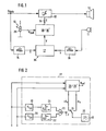
- a microphone (11) is used, which sometimes emits the acoustic loudspeaker output signal emitted by the loudspeaker also called useful signal, and simultaneously detects the interference noise prevailing in the motor vehicle interior.
- the electrical microphone output signal is used to generate a manipulated variable (z) for one usually contained in the car radio
- Control amplifier (12) generates and amplifies the electrical useful signal U Nutz supplied to the loudspeaker as a function of the noise.
- the envelopes of the electrical useful signal U useful and the electrical microphone output signal are continuously checked for similarity and a similarity signal (x) proportional to the degree of similarity is generated.
- the envelopes are in turn more similar, the lower the noise level.
- the similarity signal (x) is compared according to a first method, as is shown in the circuit diagram in FIG. 3, with a predetermined target value U target , which is preferably predetermined as a function of the preselected volume.
- the volume is in turn set by the operator to the desired value by means of a manual volume control (13) designed as a setpoint generator (28).
- the difference between the similarity signal and the setpoint is integrated and forms the manipulated variable (z) supplied to the control amplifier (12) via its control input (14).
- the manually preset volume is changed in accordance with this manipulated variable (2).
- An upper and a lower switching threshold can be assigned to each of the threshold value stages, the control being carried out in such a way that the manipulated variable (z) is increased when the lower switching threshold is undershot and reduced when the upper switching threshold is exceeded.
- the target voltage U target is in turn predetermined by the volume control (13) designed as a target value transmitter (28).
- the electrical useful signal U Nutz applied to the input of the control amplifier (12) is fed to a first envelope detector (15) and the electrical microphone output signal to a second envelope detector (16) of a control device (36).
- the two envelope detectors (15, 16) are connected to a comparison circuit (17) which compares the two envelopes of the useful signal and the microphone output signal for similarity and generates a similarity signal at their output.
- the comparison circuit (17) is followed by a manipulated variable generator (18 or 18 '), the output of which is connected to the control input (14) of the control amplifier (12).
- FIG. 2 An embodiment of the comparison circuit (17) is shown in Fig. 2 in the block diagram.
- Each envelope detector (15, 16) is followed by the series connection of a differentiator (19 or 20) and a zero voltage comparator (21 or 22) via the inputs a and b of the comparison circuit (17).
- the outputs of the two zero voltage comparators (21, 22) are connected to a coincidence element (23), here an equivalence gate, to the output of which the control input of a changeover switch (24) is connected.
- the changeover switch (24) places an averager formed as a low pass (25) on a positive or negative voltage value U, so that an upper and a lower output value can be removed at the output of the Umx switch.
- the differentiators (19, 20) record the changes in the envelope signals. If the change, that is to say the slope of the envelope, is positive, then a logic "1" signal is present at the output of the assigned zero-voltage comparator (21 or 22), the slope is negative, a logic "0" signal. If the signs of the slopes of the two envelopes coincide, a logic "1" signal appears at the output of the coincidence element (23) and the changeover switch (24) assumes the position shown in FIG. 2. In the other case, that is, with different signs of the slopes, a logic "0” signal occurs at the output of the coincidence element (23) and the changeover switch (24) connects the low-pass filter (25) to the voltage value -U.
- the temporal mean value of the voltage amounts + U x and -U x applied in accordance with the signs of the slopes of the envelope is shown as a similarity signal ( x ) removable.
- This similarity signal approaches the value + U if the envelopes are the same and goes to zero if the envelopes are extremely dissimilar.
- the similarity signal (x) is fed to the manipulated variable generator (18 or 18 '), which is generated from the similarity signal ( x ) generates a manipulated variable (z) and is connected to the volume control (13) designed as a setpoint generator (28).
- the manipulated variable generator (18) has a subtractor (26) and an integrator (27) connected downstream of it.
- the similarity signal (X) is present at one input of the subtractor (26) and at the other input there is an actuating voltage U set specified by the setpoint generator (28).
- the differential voltage at the output of the subtractor (26) is integrated in the integrator (27) and fed directly to the control input (14) of the control amplifier (12) as a manipulated variable (z).
- the manipulated variable generator (18 ') has a plurality of threshold switches (40) and an equal number of switchable damping elements (41).
- the attenuators are connected in series.
- the series connection of the attenuators (41) is connected between the input connected to the setpoint generator (28) and the output of the manipulated variable generator (18 ').
- Each attenuator can be switched on and off by means of an associated threshold switch (40), which is symbolically represented by the attenuators (41) connected in / out switches (42).
- Each threshold switch (40) has an upper switching threshold and a lower switching threshold to generate a switching hysteresis.
- the respectively assigned switch (42) is opened so that the assigned damping element (41) is switched on and the manipulated variable (z) is reduced by one step. If the lower switching threshold is undershot, the assigned switch (42) is closed, so that the assigned damping element (41) is bridged, that is to say switched off, and the manipulated variable (z) is raised by one step.
- the switching thresholds of the threshold switches (40) are graduated from one another in such a way that the control behavior is optimally adapted to the subjective perception of volume by the human ear. If the similarity signal (i) assumes its greatest value U x (which means that the microphone output signal and the useful signal are identical, that is to say there is no interference noise), then all switches (42) are open.
- the manipulated variable (z) supplied to the control amplifier (12) is minimal and depends exclusively on the setting of the volume control (13). As soon as a noise occurs, the envelope signals are less similar, the value of the similarity signal (x) decreases. As soon as the lower switching threshold of the first threshold switch (40) is undershot, the assigned switch (42) is closed and the manipulated variable (z) is increased by one step. If the next lower switching threshold is undershot, the next threshold switch (40) responds and the control voltage U target is increased by a further, e.g. B. increased the same amount and so away. If the envelope signals are extremely dissimilar, the similarity signal ( x ) is approximately zero and all switches (42) are closed. The manipulated variable (z) supplied to the control amplifier (12) is maximum.
- the threshold switches (40) can, for. B. be designed as a Schmitt trigger.
- the control mechanism described above takes advantage of the dynamics of the signals.
- the output values + U x and -U x present at the output of the changeover switch (24) are weighted for detecting such noise signals.
- the mean value and the dynamic range are determined from the envelope signals of the useful signal on the one hand and the microphone output signal on the other hand at the inputs a and b of the comparison circuit (17).
- a dynamic or weighting factor is obtained from these mean values and dynamic ranges, which is used to weight these output values.
- the dynamic factor is calculated as the quotient of the two envelope curve ratios of the envelope curve signals. Envelope ratios are understood to mean the quotient of the mean value to the dynamic range of an envelope signal.
- the dynamic factor is the difference between the mean value of the envelope signal derived from the microphone output signal and the ratio of the dynamic ranges of the microphone output signal and the useful signal multiplied by the mean value of the useful signal envelope signal derived envelope signals formed.
- the weighting is then carried out in such a way that the larger output value is reduced by the dynamic factor and the smaller output value is increased by the dynamic factor.
- the comparison circuit (17) has a weighting device (29 or 29 '), which is shown in detail in FIGS. 5 and 6, respectively.
- the inputs a and b of the comparison circuit (17) connected to the envelope detectors (15, 16) each have an averager designed as a low-pass filter (30 or 31) and a dynamic detector (32 or 33 ) connected.
- the dynamic detectors (32, 33) are converters for converting the peak-to-peak value of the envelope signals into a DC voltage.
- Such a converter can consist of two peak value detectors and a subtractor, a peak value detector in each case detecting the upper and lower peak value of the envelope signal.
- the outputs of the two low-pass filters (30, 31) and the two dynamic detectors (32, 33) are connected to an arithmetic unit (34 and 34 ').
- a DC voltage value U 5 or U 5 can be removed, which is directly as a weighted voltage value + U x at the input of the switch (24) and via a negator (35 or 35') is present as a weighted voltage value -U x at the other input of the switch (24).
- the arithmetic unit (34) in FIG. 5 forms the averaging means (30, 31) and the dynamic detectors (32, 33) and one from the output voltages U 1 to U 4 DC reference voltage U ref 'corresponds to the DC voltage U 5
- the dynamic factor a is 1 if there is no noise and otherwise always less than 1.
- the weighting device (29) thus ensures that the larger voltage value + U x decreases by an amount determined by the dynamic factor a and the smaller voltage value -U x by the same amount is increased if the envelope curve ratio U 3 / U 4 assigned to the microphone output signal is greater than the envelope curve ratio U 1 / U 2 associated with the useful signal.
- the envelope curve ratio denotes the ratio of the mean value U 1 or U 3 to the peak-to-peak value U 2 or U 4 of the envelope curve signals at the inputs a or b of the comparison circuit 17.
- the arithmetic unit (34 ') in the weighting device (29') in FIG. 6 forms the input voltages U 1 to U 4 of the low-pass filters (30, 31) and the dynamic end tectors (32, 33) and the reference DC voltage U ref , which corresponds to the maximum value of the microphone signal, the voltage U ' S according to
- the arithmetic unit (34 ') has a divider (43), a multiplier (44) and an adder (45), which in the manner shown in FIG. 6 with each other and with the outputs of the low-pass filters (30, 31) and Dynamic detectors (32, 33) are connected.
- An inverter (46) is also connected between the input of the adder (45) and the output of the low pass (31).
- the voltage U ' S is in turn fed to the changeover switch (24) as a weighted voltage value + U x or -U x .
- the dynamic factor b according to is always zero when there is no noise and goes against U ref with increasing noise.
- the similarity comparison of the envelopes of the electrical useful signal U Nutz and the electrical microphone output signal is only carried out outside of signal pauses in the useful signal.
- the signal pauses are detected in the useful signal and the similarity comparison is prevented during these signal pauses.
- This prevents the similarity signal from becoming very small in the case of pauses in the presence of background noise and thus inadmissibly leading to a large manipulated variable.
- the volume can be adjusted and the manipulated variable (z) can only be changed if the value of the manipulated variable (z) is outside a specified tolerance window.
- the manipulated variable generator (18) according to FIG.
- this tolerance window is placed around the target value U target .
- the invention is not restricted to the exemplary embodiment of the analog circuit arrangement described above.
- the method according to the invention can thus be implemented digitally.
- the voltage values + U x and -U x are digital values with a predetermined size or zero, the mean value of which is calculated in an ALU and forms the digital similarity signal (x).
- the method works in the same way and the mode of operation of the digital device is as described above, taking into account the special features required by digital technology.
- an exclusive-OR gate can also form a coincidence circuit together with the changeover switch (24).
- the output signals of the exclusive-OR gate are interchanged with those of the coincidence element (23) when the switch (24) is in the same position.
Landscapes
- Control Of Amplification And Gain Control (AREA)
- Circuit For Audible Band Transducer (AREA)
Priority Applications (1)
| Application Number | Priority Date | Filing Date | Title |
|---|---|---|---|
| AT84110248T ATE42655T1 (de) | 1983-09-22 | 1984-08-29 | Verfahren zum anpassen der lautstaerke eines lautsprechers an einen am lautsprecherort herrschenden stoergeraeuschpegel. |
Applications Claiming Priority (2)
| Application Number | Priority Date | Filing Date | Title |
|---|---|---|---|
| DE3334262 | 1983-09-22 | ||
| DE3334262 | 1983-09-22 |
Publications (3)
| Publication Number | Publication Date |
|---|---|
| EP0141129A2 true EP0141129A2 (fr) | 1985-05-15 |
| EP0141129A3 EP0141129A3 (en) | 1985-10-16 |
| EP0141129B1 EP0141129B1 (fr) | 1989-04-26 |
Family
ID=6209770
Family Applications (1)
| Application Number | Title | Priority Date | Filing Date |
|---|---|---|---|
| EP84110248A Expired EP0141129B1 (fr) | 1983-09-22 | 1984-08-29 | Méthode pour adapter le volume sonore d'un haut-parleur au niveau du bruit ambiant |
Country Status (4)
| Country | Link |
|---|---|
| EP (1) | EP0141129B1 (fr) |
| JP (1) | JPS60106216A (fr) |
| AT (1) | ATE42655T1 (fr) |
| DE (1) | DE3477982D1 (fr) |
Cited By (3)
| Publication number | Priority date | Publication date | Assignee | Title |
|---|---|---|---|---|
| EP0641070A1 (fr) * | 1993-08-27 | 1995-03-01 | Blaupunkt-Werke GmbH | Méthode et dispositif de commande du volume sonore en fonction du niveau de bruit ambiant |
| WO2002089452A1 (fr) | 2001-04-26 | 2002-11-07 | Harman/Becker Automotive Systems (Straubing Division) Gmbh | Circuit assurant une reproduction audio et presentant une fonction mains libres monte dans un vehicule automobile |
| US6529605B1 (en) | 2000-04-14 | 2003-03-04 | Harman International Industries, Incorporated | Method and apparatus for dynamic sound optimization |
Families Citing this family (1)
| Publication number | Priority date | Publication date | Assignee | Title |
|---|---|---|---|---|
| US5766344A (en) | 1991-09-21 | 1998-06-16 | Semiconductor Energy Laboratory Co., Ltd. | Method for forming a semiconductor |
Family Cites Families (1)
| Publication number | Priority date | Publication date | Assignee | Title |
|---|---|---|---|---|
| JPS55147014A (en) * | 1979-05-07 | 1980-11-15 | Hitachi Ltd | Automatic adjusting unit for sound volume and sound quality |
-
1984
- 1984-08-29 EP EP84110248A patent/EP0141129B1/fr not_active Expired
- 1984-08-29 AT AT84110248T patent/ATE42655T1/de not_active IP Right Cessation
- 1984-08-29 DE DE8484110248T patent/DE3477982D1/de not_active Expired
- 1984-09-17 JP JP59192779A patent/JPS60106216A/ja active Pending
Non-Patent Citations (3)
| Title |
|---|
| ELECTRICAL DESIGN NEWS, Band 26, Nr. 1, 7. Januar 1981, Seite 202, Boston, Massachusetts, US; J. GRAEME: "Feedback lowers AGC distortion" * |
| RADIO FERNSEHEN ELEKTRONIK, Band 29, Nr. 8, August 1980, Seite 539, Berlin, DE; "Störgeräuschabhängige automatische Lautstärkesteuerung" * |
| TECHNISCHE MITTEILUNGEN AEG-TELEFUNKEN, Band 61, Nr. 3, 1971, Seiten 186-189; A. HÄFNER: "Geräuschabhängige elektronische Lautstärkeeinstellung EL 100" * |
Cited By (3)
| Publication number | Priority date | Publication date | Assignee | Title |
|---|---|---|---|---|
| EP0641070A1 (fr) * | 1993-08-27 | 1995-03-01 | Blaupunkt-Werke GmbH | Méthode et dispositif de commande du volume sonore en fonction du niveau de bruit ambiant |
| US6529605B1 (en) | 2000-04-14 | 2003-03-04 | Harman International Industries, Incorporated | Method and apparatus for dynamic sound optimization |
| WO2002089452A1 (fr) | 2001-04-26 | 2002-11-07 | Harman/Becker Automotive Systems (Straubing Division) Gmbh | Circuit assurant une reproduction audio et presentant une fonction mains libres monte dans un vehicule automobile |
Also Published As
| Publication number | Publication date |
|---|---|
| DE3477982D1 (en) | 1989-06-01 |
| ATE42655T1 (de) | 1989-05-15 |
| EP0141129B1 (fr) | 1989-04-26 |
| JPS60106216A (ja) | 1985-06-11 |
| EP0141129A3 (en) | 1985-10-16 |
Similar Documents
| Publication | Publication Date | Title |
|---|---|---|
| DE3426068C2 (fr) | ||
| DE4038805C2 (de) | Vorrichtung zum automatischen Einstellen der Lautstärke | |
| EP1366564B1 (fr) | Dispositif permettant la regulation de l'intensite sonore independamment du bruit | |
| EP0290952B1 (fr) | Montage pour commande de la parole pour un terminal de télécommunication | |
| DE69628411T2 (de) | Vorrichtung und Verfahren zur Geräuschreduzierung eines Sprachsignals | |
| DE69618407T2 (de) | Verfahren und Schaltung zur Tonsignalverarbeitung | |
| DE2345544C3 (de) | Schallwiedergabesystem | |
| DE4021969C2 (de) | Automatische Lautstärkeregelung | |
| DE3802903C2 (fr) | ||
| DE3887786T2 (de) | Elektronisches Fernmeldegerät mit Rauschunterdrückungsfunktion. | |
| DE69600728T2 (de) | Vorrichtung und verfahren zur signalqualitätserfassung | |
| DE4017596A1 (de) | Vorrichtung zur automatischen lautstaerkesteuerung in fahrzeugen | |
| DE3315150A1 (de) | Selbsttaetige lautstaerke-regelvorrichtung | |
| DE69925259T2 (de) | Empfänger mit rückkopplungsschaltung für die verstärkungregelung | |
| CH644974A5 (de) | Schaltungsanordnung zum selbsttaetigen anpassen der lautstaerke mindestens eines lautsprechers an einen am lautsprecherort herrschenden stoergeraeuschpegel fuer rundfunkempfaenger. | |
| DE3525472A1 (de) | Anordnung zum detektieren impulsartiger stoerungen und anordnung zum unterdruecken impulsartiger stoerungen mit einer anordnung zum detektieren impulsartiger stoerungen | |
| DE102009016845B3 (de) | Anordnung und Verfahren zur Erkennung von Rückkopplungen bei Hörvorrichtungen | |
| DE2846234C3 (de) | Schaltungsanordnung zur automatischen Verstärkungsregelung eines Einseitenband-Empfängers | |
| DE10225145A1 (de) | Verfahren zur gehörrichtigen Baßpegelanhebung und zugeordnetes Wiedergabesystem | |
| EP0600164A1 (fr) | Procédé pour l'amélioration de la qualité de transmission d'un dispositif électro-acoustique | |
| EP0141129B1 (fr) | Méthode pour adapter le volume sonore d'un haut-parleur au niveau du bruit ambiant | |
| EP0027519A1 (fr) | Montage de commande automatique du volume sonore d'un haut-parleur en fonction du niveau de bruit ambiant | |
| EP1458216B1 (fr) | Appareil et procédé à l'adaption de microphones dans une prothèse auditive | |
| DE69524331T2 (de) | Schaltung zur automatischen Verstärkungsregelung und Vorrichtung mit einer solchen Schaltung | |
| EP0140333A2 (fr) | Système de reproduction de sons |
Legal Events
| Date | Code | Title | Description |
|---|---|---|---|
| PUAI | Public reference made under article 153(3) epc to a published international application that has entered the european phase |
Free format text: ORIGINAL CODE: 0009012 |
|
| AK | Designated contracting states |
Designated state(s): AT CH DE FR GB IT LI |
|
| PUAL | Search report despatched |
Free format text: ORIGINAL CODE: 0009013 |
|
| AK | Designated contracting states |
Designated state(s): AT CH DE FR GB IT LI |
|
| 17P | Request for examination filed |
Effective date: 19860318 |
|
| 17Q | First examination report despatched |
Effective date: 19870810 |
|
| GRAA | (expected) grant |
Free format text: ORIGINAL CODE: 0009210 |
|
| AK | Designated contracting states |
Kind code of ref document: B1 Designated state(s): AT CH DE FR GB IT LI |
|
| REF | Corresponds to: |
Ref document number: 42655 Country of ref document: AT Date of ref document: 19890515 Kind code of ref document: T |
|
| GBT | Gb: translation of ep patent filed (gb section 77(6)(a)/1977) | ||
| REF | Corresponds to: |
Ref document number: 3477982 Country of ref document: DE Date of ref document: 19890601 |
|
| ET | Fr: translation filed | ||
| ITF | It: translation for a ep patent filed | ||
| PLBE | No opposition filed within time limit |
Free format text: ORIGINAL CODE: 0009261 |
|
| STAA | Information on the status of an ep patent application or granted ep patent |
Free format text: STATUS: NO OPPOSITION FILED WITHIN TIME LIMIT |
|
| 26N | No opposition filed | ||
| ITTA | It: last paid annual fee | ||
| PGFP | Annual fee paid to national office [announced via postgrant information from national office to epo] |
Ref country code: GB Payment date: 19960809 Year of fee payment: 13 |
|
| PGFP | Annual fee paid to national office [announced via postgrant information from national office to epo] |
Ref country code: FR Payment date: 19960814 Year of fee payment: 13 |
|
| PGFP | Annual fee paid to national office [announced via postgrant information from national office to epo] |
Ref country code: AT Payment date: 19960820 Year of fee payment: 13 |
|
| PGFP | Annual fee paid to national office [announced via postgrant information from national office to epo] |
Ref country code: CH Payment date: 19960823 Year of fee payment: 13 |
|
| PGFP | Annual fee paid to national office [announced via postgrant information from national office to epo] |
Ref country code: DE Payment date: 19961024 Year of fee payment: 13 |
|
| PG25 | Lapsed in a contracting state [announced via postgrant information from national office to epo] |
Ref country code: GB Free format text: LAPSE BECAUSE OF NON-PAYMENT OF DUE FEES Effective date: 19970829 Ref country code: AT Free format text: LAPSE BECAUSE OF NON-PAYMENT OF DUE FEES Effective date: 19970829 |
|
| PG25 | Lapsed in a contracting state [announced via postgrant information from national office to epo] |
Ref country code: LI Free format text: LAPSE BECAUSE OF NON-PAYMENT OF DUE FEES Effective date: 19970831 Ref country code: CH Free format text: LAPSE BECAUSE OF NON-PAYMENT OF DUE FEES Effective date: 19970831 |
|
| REG | Reference to a national code |
Ref country code: CH Ref legal event code: PL |
|
| GBPC | Gb: european patent ceased through non-payment of renewal fee |
Effective date: 19970829 |
|
| PG25 | Lapsed in a contracting state [announced via postgrant information from national office to epo] |
Ref country code: FR Free format text: LAPSE BECAUSE OF NON-PAYMENT OF DUE FEES Effective date: 19980430 |
|
| PG25 | Lapsed in a contracting state [announced via postgrant information from national office to epo] |
Ref country code: DE Free format text: LAPSE BECAUSE OF NON-PAYMENT OF DUE FEES Effective date: 19980501 |
|
| REG | Reference to a national code |
Ref country code: FR Ref legal event code: ST |