EP0141306B1 - Raccord de cornière d'angle en deux morceaux pour brides d'assemblage de canaux en tôle - Google Patents
Raccord de cornière d'angle en deux morceaux pour brides d'assemblage de canaux en tôle Download PDFInfo
- Publication number
- EP0141306B1 EP0141306B1 EP84112078A EP84112078A EP0141306B1 EP 0141306 B1 EP0141306 B1 EP 0141306B1 EP 84112078 A EP84112078 A EP 84112078A EP 84112078 A EP84112078 A EP 84112078A EP 0141306 B1 EP0141306 B1 EP 0141306B1
- Authority
- EP
- European Patent Office
- Prior art keywords
- piece
- corner angle
- contact surface
- leg
- pieces
- Prior art date
- Legal status (The legal status is an assumption and is not a legal conclusion. Google has not performed a legal analysis and makes no representation as to the accuracy of the status listed.)
- Expired
Links
- 239000002184 metal Substances 0.000 title description 5
- 238000003780 insertion Methods 0.000 claims abstract description 5
- 230000037431 insertion Effects 0.000 claims abstract description 5
- 230000003014 reinforcing effect Effects 0.000 claims abstract description 5
- 238000005452 bending Methods 0.000 description 6
- 230000002787 reinforcement Effects 0.000 description 2
- 230000007704 transition Effects 0.000 description 2
- 208000027418 Wounds and injury Diseases 0.000 description 1
- 230000000903 blocking effect Effects 0.000 description 1
- 238000010276 construction Methods 0.000 description 1
- 230000006378 damage Effects 0.000 description 1
- 208000014674 injury Diseases 0.000 description 1
- 238000000034 method Methods 0.000 description 1
- 238000007789 sealing Methods 0.000 description 1
- 239000004544 spot-on Substances 0.000 description 1
Images
Classifications
-
- F—MECHANICAL ENGINEERING; LIGHTING; HEATING; WEAPONS; BLASTING
- F16—ENGINEERING ELEMENTS AND UNITS; GENERAL MEASURES FOR PRODUCING AND MAINTAINING EFFECTIVE FUNCTIONING OF MACHINES OR INSTALLATIONS; THERMAL INSULATION IN GENERAL
- F16L—PIPES; JOINTS OR FITTINGS FOR PIPES; SUPPORTS FOR PIPES, CABLES OR PROTECTIVE TUBING; MEANS FOR THERMAL INSULATION IN GENERAL
- F16L23/00—Flanged joints
- F16L23/12—Flanged joints specially adapted for particular pipes
- F16L23/14—Flanged joints specially adapted for particular pipes for rectangular pipes
-
- F—MECHANICAL ENGINEERING; LIGHTING; HEATING; WEAPONS; BLASTING
- F16—ENGINEERING ELEMENTS AND UNITS; GENERAL MEASURES FOR PRODUCING AND MAINTAINING EFFECTIVE FUNCTIONING OF MACHINES OR INSTALLATIONS; THERMAL INSULATION IN GENERAL
- F16B—DEVICES FOR FASTENING OR SECURING CONSTRUCTIONAL ELEMENTS OR MACHINE PARTS TOGETHER, e.g. NAILS, BOLTS, CIRCLIPS, CLAMPS, CLIPS OR WEDGES; JOINTS OR JOINTING
- F16B2200/00—Constructional details of connections not covered for in other groups of this subclass
- F16B2200/65—Miter joints
-
- F—MECHANICAL ENGINEERING; LIGHTING; HEATING; WEAPONS; BLASTING
- F16—ENGINEERING ELEMENTS AND UNITS; GENERAL MEASURES FOR PRODUCING AND MAINTAINING EFFECTIVE FUNCTIONING OF MACHINES OR INSTALLATIONS; THERMAL INSULATION IN GENERAL
- F16B—DEVICES FOR FASTENING OR SECURING CONSTRUCTIONAL ELEMENTS OR MACHINE PARTS TOGETHER, e.g. NAILS, BOLTS, CIRCLIPS, CLAMPS, CLIPS OR WEDGES; JOINTS OR JOINTING
- F16B2200/00—Constructional details of connections not covered for in other groups of this subclass
- F16B2200/67—Rigid angle couplings
-
- Y—GENERAL TAGGING OF NEW TECHNOLOGICAL DEVELOPMENTS; GENERAL TAGGING OF CROSS-SECTIONAL TECHNOLOGIES SPANNING OVER SEVERAL SECTIONS OF THE IPC; TECHNICAL SUBJECTS COVERED BY FORMER USPC CROSS-REFERENCE ART COLLECTIONS [XRACs] AND DIGESTS
- Y10—TECHNICAL SUBJECTS COVERED BY FORMER USPC
- Y10T—TECHNICAL SUBJECTS COVERED BY FORMER US CLASSIFICATION
- Y10T403/00—Joints and connections
- Y10T403/55—Member ends joined by inserted section
- Y10T403/555—Angle section
Definitions
- the invention relates to a corner elbow according to the preamble of claim 1.
- Such a corner piece is known from German utility model 7408661.
- Two-part corner elbows are mainly required when connecting flanges are molded directly onto the sheet metal duct wall and the individual duct sections are made from sheet metal angle parts comprising two duct walls or even from one part. In this case, one-piece corner elbows can no longer be inserted into the open profiles of the connecting flanges.
- the use of two-part corner elbows is also very advantageous if duct sections are delivered in disassembled form to a construction site for transport reasons and are assembled there.
- the associated flange profiles are then also already attached to the duct wall, for example spot-welded.
- the corner elbows must also be subsequently inserted into the open profiles of the connecting flanges. In principle, it would be possible to insert a one-piece corner elbow during the assembly of the channel walls, but this is avoided as much as possible because of the difficult handling.
- the two-part corner elbow known from the utility model specification has some application disadvantages.
- the second section is lifted when it is inserted from the already inserted first section and jams in the flange profile. It must therefore be hammered into the fully inserted position and, as a result of being lifted by the first section, expands the profile cavity. As a result, it sits loosely in the connecting flange after it has been fully inserted, since its profile does not spring together after expansion.
- Another disadvantage can be seen in the fact that both sections between contact surfaces and legs are strongly stressed to bend when the corner angle pieces of two abutting channel sections are screwed together and bend slightly in the transition area between contact surface and legs.
- the invention has for its object to improve the known corner elbow so that when it is inserted into the connecting flanges there is no widening or injury, and when screwing there is no bending or kinking of the sections.
- the second section Since the second section is continuously flat, it can be pushed into the open profile of the connecting flange by hand without any obstacle through the guide groove provided on the first section. This does not widen the profile. Both sections are essentially not weakened in the critical transition area between the contact surface and the leg, since larger sheet thicknesses can be used without being obstructed during insertion. The mutual interlocking of the sections also holds when the sheet metal channel is subjected to a strong corner buckling load, since the contact surfaces of the sections lie smoothly against one another and are not subjected to bending during insertion and subsequent tightening of the screws. The guidance of the second section in the guide groove of the first section also ensures a firm fit of the parts that cannot avoid each other.
- a further reinforcement of the first section in the area critical to bending is achieved by the reinforcement web according to claim 2.
- This reinforcing web can be produced in a particularly simple and stable manner according to claims 3 and 4, but can also take other shapes to adapt to any profile shapes of the connecting flanges.
- this labor-intensive process is avoided by merely pressing the protruding attachment of the first section into the recess or bevel of the second section, for example by a single hammer blow, with the attachment already being flanged at an angle of about 45 ° is sufficient for completely blocking the second section.
- the second section lies in the guide groove of the first section, the latter is fixed and prevented from slipping out.
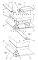
- the first section is generally designated 10 and the second section generally designated 12.
- Both sections have a leg 14 or 16 formed as a flat plate and an associated flat contact surface 18 or 20.
- Both contact surfaces have a flanged edge 22 or 24 on the side opposite the leg 14 or 16.
- the first section 10 also has an offset 26 which, together with the contact surface 18 and the flanged edge 22, forms a guide groove 28 in which the first section 12 is securely guided when it is pushed into the associated connecting flange.
- Both contact surfaces 18 and 20 have in the assembled state according to.
- Fig. 3 overlapping screw holes 30 and 32 respectively.
- the first section 10 bears along its one edge a web 34 which is bent up in one piece and extends essentially over the length of the leg 14 and overlaps part of the contact surface 18, which comes into contact with the inside of the flange profile and has very good bending rigidity of the contact surface 18 guaranteed with respect to the leg 14.
- the corner angle piece according to the invention is inserted according to FIGS. 2 and 3 into the open profile ends 40 of essentially triangular connecting flanges 36 and 38, which are punctured at the end of a sheet metal channel section 42 by spot welds 48.
- the first corner angle piece 10 is first inserted into the connecting flange 38 in such a way that the web 34 stands upwards in the position shown and bears against the inner profile wall.
- the second section 12 is then pushed through the groove 28 of the first section 10 into the other connecting flange 36 until the flanged edge 24 abuts the outer edge of the contact surface 18.
- the projection 44 of the first section protruding beyond the outer edge of the contact surface 18 is turned in by approximately 45 °, so that it bears against the bevel 46 of the second section and thereby locks the position thereof.
Landscapes
- Engineering & Computer Science (AREA)
- General Engineering & Computer Science (AREA)
- Mechanical Engineering (AREA)
- Duct Arrangements (AREA)
- Flanged Joints, Insulating Joints, And Other Joints (AREA)
- Protection Of Pipes Against Damage, Friction, And Corrosion (AREA)
- Details Of Indoor Wiring (AREA)
- Connection Of Plates (AREA)
- Control Of Motors That Do Not Use Commutators (AREA)
- Semiconductor Lasers (AREA)
- Optical Head (AREA)
Claims (5)
Priority Applications (1)
| Application Number | Priority Date | Filing Date | Title |
|---|---|---|---|
| AT84112078T ATE29773T1 (de) | 1983-11-09 | 1984-10-09 | Zweiteiliges eckwinkelstueck fuer verbindungsflansche von blechkanalabschnitten. |
Applications Claiming Priority (2)
| Application Number | Priority Date | Filing Date | Title |
|---|---|---|---|
| DE3340503A DE3340503C1 (de) | 1983-11-09 | 1983-11-09 | Zweiteiliges Eckwinkelstueck fuer Verbindungsflansche von Blechkanalabschnitten |
| DE3340503 | 1983-11-09 |
Publications (2)
| Publication Number | Publication Date |
|---|---|
| EP0141306A1 EP0141306A1 (fr) | 1985-05-15 |
| EP0141306B1 true EP0141306B1 (fr) | 1987-09-16 |
Family
ID=6213860
Family Applications (1)
| Application Number | Title | Priority Date | Filing Date |
|---|---|---|---|
| EP84112078A Expired EP0141306B1 (fr) | 1983-11-09 | 1984-10-09 | Raccord de cornière d'angle en deux morceaux pour brides d'assemblage de canaux en tôle |
Country Status (6)
| Country | Link |
|---|---|
| US (1) | US4552388A (fr) |
| EP (1) | EP0141306B1 (fr) |
| AT (1) | ATE29773T1 (fr) |
| AU (1) | AU563719B2 (fr) |
| DE (1) | DE3340503C1 (fr) |
| ES (1) | ES282144Y (fr) |
Cited By (1)
| Publication number | Priority date | Publication date | Assignee | Title |
|---|---|---|---|---|
| DE202009017460U1 (de) | 2009-12-28 | 2010-03-11 | Berlinerluft. Technik Gmbh | Zweiteiliger Eckwinkel für Luftleitungskanalstücke |
Families Citing this family (20)
| Publication number | Priority date | Publication date | Assignee | Title |
|---|---|---|---|---|
| ZA845730B (en) * | 1984-01-31 | 1986-04-30 | Rafael Garcia | Flange connections for ducting |
| DE3512669A1 (de) * | 1985-04-06 | 1986-10-09 | Karl Meinig KG, 7201 Rietheim-Weilheim | Luftkanalabschnitt mit angeformtem verbindungsflansch |
| US4699343A (en) * | 1985-05-13 | 1987-10-13 | Hirsh Company | Support for workpieces |
| JPH02140553A (ja) * | 1988-08-04 | 1990-05-30 | Bullock Mfg Pty Ltd | 空調ダクト連結装置 |
| GB8826511D0 (en) * | 1988-11-12 | 1988-12-14 | Firmac Ltd | Duct jointing devices |
| US5069484A (en) * | 1990-02-09 | 1991-12-03 | Met-Coil Systems Corporation | Duct joining system |
| US5165730A (en) * | 1991-06-27 | 1992-11-24 | Mcelroy Howard J | Duct joining system |
| US5356184A (en) * | 1992-01-10 | 1994-10-18 | Industrial Air, Inc. | Corner pieces for improved duct connector |
| US5423576A (en) * | 1992-01-10 | 1995-06-13 | Industrial Air, Inc. | Corner pieces for improved duct connector |
| US5450879A (en) * | 1994-06-14 | 1995-09-19 | Met-Coil Systems Corporation | Cornerless slip-on flange system for duct connections |
| DE19547982A1 (de) * | 1995-12-21 | 1997-06-26 | Meinig Metu System | Stoßverbindung von Luftkanalabschnitten |
| AT405869B (de) * | 1998-07-08 | 1999-12-27 | Aumayr Gmbh & Co Leopold | Eckverbindung für die abgekanteten wandflansche eines im querschnitt rechtwinkeligen blechkanalschusses |
| US6536984B1 (en) * | 2000-08-18 | 2003-03-25 | James G. Ring | Taper lock fastening bracket system and method of assembly |
| DE102005042016B3 (de) * | 2005-09-02 | 2007-01-11 | Ing.-Büro H. Prechtl KG Anlagentechnik | Eckwinkelsystem für Verbindungsflansche von Blechkanalabschnitten |
| DE102005057934C5 (de) * | 2005-09-23 | 2014-03-13 | Günter Smitka | System für Klimatisierungskanäle und Eckwinkel |
| WO2007036322A1 (fr) * | 2005-09-23 | 2007-04-05 | Smitka Guenter | Systeme pour conduits de climatisation |
| DE102007012015B3 (de) * | 2007-03-13 | 2008-07-17 | Ing.-Büro H. Prechtl KG Anlagentechnik | Eckwinkelsystem für Verbindungsflanschabschnitte von Blechkanalabschnitten |
| US9212770B2 (en) * | 2007-07-18 | 2015-12-15 | RAM Developing, LLC | Method and apparatus for attaching flange portions to ducts |
| US20100187817A1 (en) * | 2009-01-29 | 2010-07-29 | Martin Stephen S | Slide corner connector for flange |
| DE202019101828U1 (de) * | 2019-04-01 | 2020-07-06 | Wildeboer Bauteile Gmbh | Flanschecke an einem Gehäuse |
Family Cites Families (4)
| Publication number | Priority date | Publication date | Assignee | Title |
|---|---|---|---|---|
| DE7408661U (fr) * | 1974-09-19 | Meinig K Kg | ||
| FR1278118A (fr) * | 1960-10-26 | 1961-12-08 | Grames | Assemblage de profilés métalliques de section à contour fermé et sabot permettant cet assemblage |
| US3272582A (en) * | 1964-12-17 | 1966-09-13 | Amco Eng | Building components for constructing cabinets |
| DE2501611C3 (de) * | 1975-01-16 | 1980-01-24 | Fa. Georg Gabriel, 8035 Gauting. | Flanschverbindung für rechteckige Klimatisierungskanäle |
-
1983
- 1983-11-09 DE DE3340503A patent/DE3340503C1/de not_active Expired
-
1984
- 1984-10-09 AT AT84112078T patent/ATE29773T1/de not_active IP Right Cessation
- 1984-10-09 EP EP84112078A patent/EP0141306B1/fr not_active Expired
- 1984-10-19 ES ES1984282144U patent/ES282144Y/es not_active Expired
- 1984-11-05 US US06/668,312 patent/US4552388A/en not_active Expired - Lifetime
- 1984-11-08 AU AU35229/84A patent/AU563719B2/en not_active Ceased
Cited By (1)
| Publication number | Priority date | Publication date | Assignee | Title |
|---|---|---|---|---|
| DE202009017460U1 (de) | 2009-12-28 | 2010-03-11 | Berlinerluft. Technik Gmbh | Zweiteiliger Eckwinkel für Luftleitungskanalstücke |
Also Published As
| Publication number | Publication date |
|---|---|
| EP0141306A1 (fr) | 1985-05-15 |
| ATE29773T1 (de) | 1987-10-15 |
| DE3340503C1 (de) | 1985-02-07 |
| AU3522984A (en) | 1985-05-30 |
| ES282144Y (es) | 1985-10-16 |
| US4552388A (en) | 1985-11-12 |
| AU563719B2 (en) | 1987-07-16 |
| ES282144U (es) | 1985-03-01 |
Similar Documents
| Publication | Publication Date | Title |
|---|---|---|
| EP0141306B1 (fr) | Raccord de cornière d'angle en deux morceaux pour brides d'assemblage de canaux en tôle | |
| EP0115246A1 (fr) | Collier de serrage | |
| DE3346171A1 (de) | Als leichtbauprofil ausgebildete profilleiste, insbesondere deckentrageprofil | |
| DE4322253A1 (de) | Schalung mit Schaltafeln und Verbindungsmitteln | |
| CH663336A5 (de) | Kasten. | |
| DE10042087A1 (de) | Verstärkungssystem für einen Kraftfahrzeugkotflügel und eine Klammer dafür | |
| DE3729215C1 (de) | Stulpschienen-Eckverbindung | |
| DE2138966A1 (de) | Vorgefertigte flanschverbindung | |
| EP0047467A1 (fr) | Joint à brides pour parties de conduit en métal laminé, notamment pour parties de conduit pour aérateurs | |
| DE2923903C2 (fr) | ||
| DE3047904C2 (de) | Elastomeres Dehnprofil zum Abdichten von bauwerkseitigen Dehnungsfugen | |
| EP2447434A1 (fr) | Sous-structure de plafond métallique | |
| DE8805874U1 (de) | Vorrichtung zum unmittelbaren Verbinden von rechtwinklig zueinander angeordneten Platinen | |
| DE8705531U1 (de) | Vorrichtung zur lösbaren Verbindung zweier stumpf aneinanderstoßender Rohre | |
| DE2926621C2 (de) | Bauelement zur Herstellung ptismatischer Wandkonstruktionen | |
| DE9416529U1 (de) | Abgewinkelter Eckverbinder | |
| EP0695849B1 (fr) | Dispositif d'assemblage d'angle pour éléments d'encadarement de fenêtres, portes ou similaires | |
| DE2920138A1 (de) | Schalung zum errichten von mauern aus beton | |
| EP0592843B1 (fr) | Ferrure, en particulier pour la connexion de plaques | |
| DE1809813A1 (de) | Trageskelett fuer Verkleidungsplatten | |
| DE4221754C2 (de) | Schaltschrank | |
| DE29609198U1 (de) | Druckverschluß für das lösbare Verbinden zweier Bauteile | |
| EP0152512A2 (fr) | Agrafe pour presser l'un contre l'autre deux rails profilés | |
| EP0794400A2 (fr) | Cadre support | |
| DE4316808A1 (de) | Spannstück für Rohrelemente |
Legal Events
| Date | Code | Title | Description |
|---|---|---|---|
| PUAI | Public reference made under article 153(3) epc to a published international application that has entered the european phase |
Free format text: ORIGINAL CODE: 0009012 |
|
| AK | Designated contracting states |
Designated state(s): AT CH FR GB IT LI |
|
| 17P | Request for examination filed |
Effective date: 19850326 |
|
| 17Q | First examination report despatched |
Effective date: 19861003 |
|
| RAP1 | Party data changed (applicant data changed or rights of an application transferred) |
Owner name: METU-SYSTEM MEINIG KG |
|
| ITF | It: translation for a ep patent filed | ||
| GRAA | (expected) grant |
Free format text: ORIGINAL CODE: 0009210 |
|
| AK | Designated contracting states |
Kind code of ref document: B1 Designated state(s): AT CH FR GB IT LI |
|
| REF | Corresponds to: |
Ref document number: 29773 Country of ref document: AT Date of ref document: 19871015 Kind code of ref document: T |
|
| GBT | Gb: translation of ep patent filed (gb section 77(6)(a)/1977) | ||
| ET | Fr: translation filed | ||
| PLBE | No opposition filed within time limit |
Free format text: ORIGINAL CODE: 0009261 |
|
| STAA | Information on the status of an ep patent application or granted ep patent |
Free format text: STATUS: NO OPPOSITION FILED WITHIN TIME LIMIT |
|
| 26N | No opposition filed | ||
| ITTA | It: last paid annual fee | ||
| REG | Reference to a national code |
Ref country code: GB Ref legal event code: IF02 |
|
| PGFP | Annual fee paid to national office [announced via postgrant information from national office to epo] |
Ref country code: GB Payment date: 20021004 Year of fee payment: 19 |
|
| PGFP | Annual fee paid to national office [announced via postgrant information from national office to epo] |
Ref country code: FR Payment date: 20021017 Year of fee payment: 19 |
|
| PGFP | Annual fee paid to national office [announced via postgrant information from national office to epo] |
Ref country code: AT Payment date: 20021022 Year of fee payment: 19 |
|
| PGFP | Annual fee paid to national office [announced via postgrant information from national office to epo] |
Ref country code: CH Payment date: 20030131 Year of fee payment: 19 |
|
| PG25 | Lapsed in a contracting state [announced via postgrant information from national office to epo] |
Ref country code: GB Free format text: LAPSE BECAUSE OF NON-PAYMENT OF DUE FEES Effective date: 20031009 Ref country code: AT Free format text: LAPSE BECAUSE OF NON-PAYMENT OF DUE FEES Effective date: 20031009 |
|
| PG25 | Lapsed in a contracting state [announced via postgrant information from national office to epo] |
Ref country code: LI Free format text: LAPSE BECAUSE OF NON-PAYMENT OF DUE FEES Effective date: 20031031 Ref country code: CH Free format text: LAPSE BECAUSE OF NON-PAYMENT OF DUE FEES Effective date: 20031031 |
|
| GBPC | Gb: european patent ceased through non-payment of renewal fee |
Effective date: 20031009 |
|
| REG | Reference to a national code |
Ref country code: CH Ref legal event code: PL |
|
| PG25 | Lapsed in a contracting state [announced via postgrant information from national office to epo] |
Ref country code: FR Free format text: LAPSE BECAUSE OF NON-PAYMENT OF DUE FEES Effective date: 20040630 |
|
| REG | Reference to a national code |
Ref country code: FR Ref legal event code: ST |