EP0141368A2 - Vantail de porte - Google Patents
Vantail de porte Download PDFInfo
- Publication number
- EP0141368A2 EP0141368A2 EP84112764A EP84112764A EP0141368A2 EP 0141368 A2 EP0141368 A2 EP 0141368A2 EP 84112764 A EP84112764 A EP 84112764A EP 84112764 A EP84112764 A EP 84112764A EP 0141368 A2 EP0141368 A2 EP 0141368A2
- Authority
- EP
- European Patent Office
- Prior art keywords
- door leaf
- metal
- tubes
- fire
- rods
- Prior art date
- Legal status (The legal status is an assumption and is not a legal conclusion. Google has not performed a legal analysis and makes no representation as to the accuracy of the status listed.)
- Granted
Links
Images
Classifications
-
- E—FIXED CONSTRUCTIONS
- E06—DOORS, WINDOWS, SHUTTERS, OR ROLLER BLINDS IN GENERAL; LADDERS
- E06B—FIXED OR MOVABLE CLOSURES FOR OPENINGS IN BUILDINGS, VEHICLES, FENCES OR LIKE ENCLOSURES IN GENERAL, e.g. DOORS, WINDOWS, BLINDS, GATES
- E06B5/00—Doors, windows, or like closures for special purposes; Border constructions therefor
- E06B5/10—Doors, windows, or like closures for special purposes; Border constructions therefor for protection against air-raid or other war-like action; for other protective purposes
- E06B5/11—Doors, windows, or like closures for special purposes; Border constructions therefor for protection against air-raid or other war-like action; for other protective purposes against burglary
-
- E—FIXED CONSTRUCTIONS
- E06—DOORS, WINDOWS, SHUTTERS, OR ROLLER BLINDS IN GENERAL; LADDERS
- E06B—FIXED OR MOVABLE CLOSURES FOR OPENINGS IN BUILDINGS, VEHICLES, FENCES OR LIKE ENCLOSURES IN GENERAL, e.g. DOORS, WINDOWS, BLINDS, GATES
- E06B5/00—Doors, windows, or like closures for special purposes; Border constructions therefor
- E06B5/10—Doors, windows, or like closures for special purposes; Border constructions therefor for protection against air-raid or other war-like action; for other protective purposes
- E06B5/16—Fireproof doors or similar closures; Adaptations of fixed constructions therefor
Definitions
- the invention relates to a door leaf consisting of a chipboard with essentially horizontally extending tubes.
- Door leaves made of chipboard are known per se.
- the tubes of the tubular chipboard run essentially horizontally.
- Such door leaves have the disadvantage that they do not provide security against burglary and can be broken open with simple means.
- Another disadvantage is that such door leaves are not fire-retardant Features include.
- the invention has for its object to provide a door leaf of the type mentioned in such a way that it offers sufficient security against break-ins.
- the door leaf has a plurality of metal bars which are pushed into individual tubes or into a plurality of the tubes of the tubular chipboard.
- the cavities formed between the inner tube wall and the metal rod in question are filled with a preferably powdery material which, according to a preferred embodiment, has fire-retardant properties.
- the invention thus creates a door leaf in which sawing is prevented by the metal rods used and which at the same time has fire-retardant properties.
- the fire-extinguishing or fire-retarding effect of the material introduced sets in and thus delays the burn-through of the door leaf.
- the tubes containing no metal rod are preferably also provided with the fire-retardant material, so that the fire-retardant property of the door leaf is further increased.
- the door leaf is provided with a circumferential metal frame which at least partially surrounds the door leaf surface in the region of the door leaf edges or projects beyond the door leaf edges.
- the Metal frame prevents access to the metal bars and access to the ends of the metal bars in the area of each vertical frame section.
- the metal rods are fixedly connected on their one end face or at their one end to the relevant vertical frame section, for example by welding, so that if the corresponding sections are observed between the metal bars and in coordination with the distances between the individual tubes in the chipboard the metal rods in the form of a comb and can be inserted into the associated tubes of the door leaf in one operation by holding one of the vertical frame sections.
- the metal rods in the form of a comb and can be inserted into the associated tubes of the door leaf in one operation by holding one of the vertical frame sections.
- the remaining cavities in the door leaf are then filled with a preferably fire-retardant material.
- the door leaf also has sound-reducing properties.
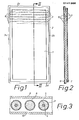
- Fig. 1 shows a schematic representation of a door leaf, which consists of a tubular chipboard 1 and a peripheral frame 2, preferably a metal frame.
- the tube chipboard 1 contains essentially horizontal tubes 3, 6, which extend completely continuously between the two front edges. From the vertical sectional view according to FIG. 2 it can be seen that the tubes 3,6 are formed at equal distances from one another.
- rods made of metal are inserted at predetermined intervals, preferably iron rods, which are denoted by 4.
- the metal rods 4 are inserted in every other tube. In this embodiment , half of all tubes 3, 6 are thus provided with a metal rod 4.
- the number of tubes in which a metal rod is inserted may depend on the height of the door and the desired security against burglary as well as on the desired maximum weight of the door leaf:
- the diameter of the metal rods 4 used is considerably smaller than the diameter of the individual tubes .
- the cavity between the inner wall of the tubes 3 and the metal rod 4 is filled with a material 5, preferably in the form of fire extinguishing powder or the like.
- the tubes that do not contain any metal rods 4 and are designated by 6 in FIG. 3 are preferably filled with the material 5.
- the material 5 has fire-retardant properties or if a fire-extinguishing powder is used as the material 5, this leads to a fire-retardant property of the entire door leaf, the fire-retardant property starting at least after a partial burn-up of the door leaf and delaying or preventing burn-through of the door leaf.
- the use of a filler material 5 ensures that the door leaf is given soundproofing or soundproofing properties.
- the metal rods 4 preferably run over the entire length of the respective tube 3, ie from one vertical metal frame section 2a to the opposite vertical frame section 2b and are gripped by the vertical metal frame sections 2b at their end faces or ends.
- the metal Frame 2 has the profile shown in Fig. 2, so that two substantially parallel legs 7, 8 of the metal frame 2 at least partially surround the door leaf and thus prevent access to the ends of the metal bars 4 in the area of the frame sections 2a, 2b.
- metal rods 4 are used which have a slightly smaller diameter than the diameter of the tubes 3 and thus have a certain intrinsic stability. These metal rods 4 are fastened, for example, to the frame part 2a in the manner of a comb, for example by welding or screwing, so that they can be inserted as a unit and fastened to the frame part 2a simultaneously into the associated tubes 3 of the chipboard 1.
- the metal bars 4 are arranged perpendicularly with respect to the door leaf folded 90 ° in relation to FIG. 1, in order then to be inserted into the tubes 3 with the aid of the frame part 2a as a holding part.
- the door leaf is then turned through 180 ° so that the frame part 2a comes to rest on the bottom and the still free tubes 6 or the remaining cavities of the tubes 3 are filled with the material.
- the metal frame is then placed and fastened overall around the door leaf in a known manner.
- the individual tubes 3, 6 With a diameter of approximately 22 mm, the individual tubes 3, 6 maintain a distance of approximately 4 mm from one another. As can be seen from FIG. 3, there is a hard fiber layer 9, 10 on both sides of the chipboard 1, which form the outer surface of the door leaf.
- the hard fiber layers have a thickness of 4 mm, for example.
- the dimensions given above are only to be considered as an example, in particular the distance between the individual tubes 3 and 6 can be larger or smaller if necessary.
- the profile of the metal frame 2 shown with reference to FIG. 2 has an essentially W-shape, the middle section coming to lie in the door edge region.
- a substantially U-shaped metal frame 2 can be used, the legs 7, 8 of which overlap the door leaf on both sides.
- any suitable, preferably also fire-retardant or fire-extinguishing agent can be used as the material 5 for filling the tube cavities, for example also a material which foams up when exposed to heat, which preferably holds the metal rods 4 in the center of each tube cavity.
Landscapes
- Engineering & Computer Science (AREA)
- Civil Engineering (AREA)
- Structural Engineering (AREA)
- Special Wing (AREA)
- Liquid Crystal (AREA)
- Laminated Bodies (AREA)
- Wing Frames And Configurations (AREA)
- Buffer Packaging (AREA)
- Vehicle Step Arrangements And Article Storage (AREA)
Priority Applications (1)
| Application Number | Priority Date | Filing Date | Title |
|---|---|---|---|
| AT84112764T ATE39728T1 (de) | 1983-10-24 | 1984-10-23 | Tuerblatt. |
Applications Claiming Priority (2)
| Application Number | Priority Date | Filing Date | Title |
|---|---|---|---|
| DE19833338581 DE3338581A1 (de) | 1983-10-24 | 1983-10-24 | Tuerblatt |
| DE3338581 | 1983-10-24 |
Publications (3)
| Publication Number | Publication Date |
|---|---|
| EP0141368A2 true EP0141368A2 (fr) | 1985-05-15 |
| EP0141368A3 EP0141368A3 (en) | 1986-06-25 |
| EP0141368B1 EP0141368B1 (fr) | 1989-01-04 |
Family
ID=6212600
Family Applications (1)
| Application Number | Title | Priority Date | Filing Date |
|---|---|---|---|
| EP84112764A Expired EP0141368B1 (fr) | 1983-10-24 | 1984-10-23 | Vantail de porte |
Country Status (4)
| Country | Link |
|---|---|
| EP (1) | EP0141368B1 (fr) |
| AT (1) | ATE39728T1 (fr) |
| DE (2) | DE3338581A1 (fr) |
| ES (1) | ES282369Y (fr) |
Cited By (5)
| Publication number | Priority date | Publication date | Assignee | Title |
|---|---|---|---|---|
| US4823530A (en) * | 1985-05-08 | 1989-04-25 | Haering Rolf A | Thermic insulating covers for facade and the like walls |
| EP0411457A1 (fr) * | 1989-08-03 | 1991-02-06 | Leo Wassner | Vantail de porte |
| NL9300949A (nl) * | 1993-06-02 | 1995-01-02 | Seac Int Bv | Wandelement. |
| AT1843U1 (de) * | 1997-01-30 | 1997-12-29 | Leo Wassner | Türblatt, insbesondere sicherheitstürblatt |
| EP4035855A1 (fr) * | 2021-01-28 | 2022-08-03 | Sauerländer Spanplatten GmbH & Co. KG | Procédé de moussage d'un panneau aggloméré à cavités tubulaires, ainsi que panneau aggloméré à cavités tubulaires |
Families Citing this family (3)
| Publication number | Priority date | Publication date | Assignee | Title |
|---|---|---|---|---|
| DE3712592A1 (de) * | 1987-04-14 | 1988-11-03 | Sommer Metallbau Stahlbau Gmbh | Tuer |
| DE4128213C2 (de) * | 1991-08-26 | 1993-09-30 | Jeche Regine | Sicherheitstür und Sicherheitsvorrichtung zum Einbau in eine Tür |
| RU2156853C2 (ru) * | 1998-06-09 | 2000-09-27 | Столбиков Владимир Иванович | Дверь |
Family Cites Families (9)
| Publication number | Priority date | Publication date | Assignee | Title |
|---|---|---|---|---|
| DE575798C (de) * | 1933-05-05 | Willy Heidrich | Tuer, Fensterladen oder Abschlusswand aus Holz mit durch verdeckt liegende Metallstaebe erhoehter Einbruchsicherheit | |
| US2070219A (en) * | 1935-05-22 | 1937-02-09 | Michael J Tracy | Door |
| FR1367730A (fr) * | 1963-06-14 | 1964-07-24 | Perfectionnements apportés aux portes, plus spécialement du type coupe-feu | |
| DE2638168A1 (de) * | 1976-08-25 | 1978-03-02 | Josef Gail | Feuerschutztuere und verfahren zur herstellung derselben |
| DE2653056C3 (de) * | 1976-11-23 | 1981-04-23 | Bochumer Eisenhütte Heintzmann GmbH & Co, 4630 Bochum | Schutzvorrichtung für die Luftdurchtrittsbereiche von Räumen oder Gebäuden |
| AT360732B (de) * | 1977-07-25 | 1981-01-26 | Reinberg Ing Josef | Platte, insbesondere tuerblatt |
| DE3025944A1 (de) * | 1980-07-09 | 1982-02-04 | Helmut 8360 Deggendorf Lilge | Gebaeudetuer |
| DE8230161U1 (de) * | 1982-10-27 | 1983-02-03 | Schröders, Theo, 5140 Erkelenz | Tuerblatt |
| DE8300729U1 (de) * | 1983-01-13 | 1983-04-14 | Biergans, Günther, 6116 Eppertshausen | Sicherheitstuerblatt |
-
1983
- 1983-10-24 DE DE19833338581 patent/DE3338581A1/de not_active Withdrawn
-
1984
- 1984-10-23 DE DE8484112764T patent/DE3475930D1/de not_active Expired
- 1984-10-23 AT AT84112764T patent/ATE39728T1/de not_active IP Right Cessation
- 1984-10-23 EP EP84112764A patent/EP0141368B1/fr not_active Expired
- 1984-10-24 ES ES1984282369U patent/ES282369Y/es not_active Expired
Cited By (7)
| Publication number | Priority date | Publication date | Assignee | Title |
|---|---|---|---|---|
| US4823530A (en) * | 1985-05-08 | 1989-04-25 | Haering Rolf A | Thermic insulating covers for facade and the like walls |
| EP0411457A1 (fr) * | 1989-08-03 | 1991-02-06 | Leo Wassner | Vantail de porte |
| DE3925758A1 (de) * | 1989-08-03 | 1991-02-14 | Leo Wassner | Tuerblatt |
| NL9300949A (nl) * | 1993-06-02 | 1995-01-02 | Seac Int Bv | Wandelement. |
| AT1843U1 (de) * | 1997-01-30 | 1997-12-29 | Leo Wassner | Türblatt, insbesondere sicherheitstürblatt |
| EP4035855A1 (fr) * | 2021-01-28 | 2022-08-03 | Sauerländer Spanplatten GmbH & Co. KG | Procédé de moussage d'un panneau aggloméré à cavités tubulaires, ainsi que panneau aggloméré à cavités tubulaires |
| US12070872B2 (en) | 2021-01-28 | 2024-08-27 | Sauerländer Spanplatten GmbH & Co. KG | Method for foaming chipboards with tubes and a chipboard with tubes |
Also Published As
| Publication number | Publication date |
|---|---|
| DE3338581A1 (de) | 1985-06-27 |
| ES282369Y (es) | 1986-01-16 |
| ATE39728T1 (de) | 1989-01-15 |
| EP0141368B1 (fr) | 1989-01-04 |
| DE3475930D1 (de) | 1989-02-09 |
| ES282369U (es) | 1985-06-01 |
| EP0141368A3 (en) | 1986-06-25 |
Similar Documents
| Publication | Publication Date | Title |
|---|---|---|
| DE3200310A1 (de) | Gestell aus mehreren profilstaeben | |
| WO2003079373A1 (fr) | Lame, collimateur multilames, dispositif pour delimiter un faisceau de rayonnement et appareil d'irradiation | |
| EP0141368B1 (fr) | Vantail de porte | |
| DE3640319A1 (de) | Hohlprofilstab fuer rolladen oder rolltore | |
| AT391523B (de) | Feuerschutztuer | |
| DE2543685C2 (de) | Dichtung für Türen, Fenster oder dgl. sowie Verfahren zu deren Herstellung | |
| EP0411457B1 (fr) | Vantail de porte | |
| DE2649421C3 (de) | Gehäuse für ein Treibstangenschloß und zwei von diesem längsverstellbare Treibstangen | |
| DE2302235C3 (de) | Rahmenprofil für Fenster, Türen o.dgl | |
| DE102020108412A1 (de) | Extrudiertes Fenster- oder Tür-Hohlkammerprofil, System mit einem solchen Hohlkammerprofil und daraus hergestellter Rahmen | |
| DE3907280C2 (de) | Tür, insbesondere für in Räumen oder Etagen angeordnete Trennwände | |
| DE3712592C2 (fr) | ||
| DE1934548A1 (de) | Tuerzarge | |
| DE3590444C2 (de) | Rollgitter | |
| DE2623781C3 (de) | Verkleidungsprofil für alte Blendrahmen | |
| DE3512856A1 (de) | Verbesserungen an abgeschirmten und/oder gepanzerten tueren | |
| DE2301752A1 (de) | Jalousie | |
| DE10300240A1 (de) | Glaswand | |
| AT404275B (de) | Fassade oder dach in metall-glas-ausfuehrung | |
| DE1986181U (de) | Profilleiste mit eckverbindevorrichtung. | |
| DE69208420T2 (de) | Gelenkvorrichtung für Rolladen | |
| DE3327950C2 (de) | Rahmenhohlprofil für Fenster-, Tür- und Trennwandelemente | |
| DE8300729U1 (de) | Sicherheitstuerblatt | |
| DE3506096C1 (de) | Tresorwandung | |
| DE202021106848U1 (de) | Modulares Gittergeländer für einen französischen Balkon |
Legal Events
| Date | Code | Title | Description |
|---|---|---|---|
| PUAI | Public reference made under article 153(3) epc to a published international application that has entered the european phase |
Free format text: ORIGINAL CODE: 0009012 |
|
| AK | Designated contracting states |
Designated state(s): AT BE CH DE FR GB IT LI LU NL SE |
|
| RTI1 | Title (correction) | ||
| PUAL | Search report despatched |
Free format text: ORIGINAL CODE: 0009013 |
|
| AK | Designated contracting states |
Kind code of ref document: A3 Designated state(s): AT BE CH DE FR GB IT LI LU NL SE |
|
| 17P | Request for examination filed |
Effective date: 19861003 |
|
| 17Q | First examination report despatched |
Effective date: 19870211 |
|
| GRAA | (expected) grant |
Free format text: ORIGINAL CODE: 0009210 |
|
| AK | Designated contracting states |
Kind code of ref document: B1 Designated state(s): AT BE CH DE FR GB IT LI LU NL SE |
|
| PG25 | Lapsed in a contracting state [announced via postgrant information from national office to epo] |
Ref country code: SE Effective date: 19890104 Ref country code: NL Effective date: 19890104 Ref country code: IT Free format text: LAPSE BECAUSE OF FAILURE TO SUBMIT A TRANSLATION OF THE DESCRIPTION OR TO PAY THE FEE WITHIN THE PRESCRIBED TIME-LIMIT;WARNING: LAPSES OF ITALIAN PATENTS WITH EFFECTIVE DATE BEFORE 2007 MAY HAVE OCCURRED AT ANY TIME BEFORE 2007. THE CORRECT EFFECTIVE DATE MAY BE DIFFERENT FROM THE ONE RECORDED. Effective date: 19890104 Ref country code: GB Free format text: LAPSE BECAUSE OF NON-PAYMENT OF DUE FEES Effective date: 19890104 Ref country code: FR Free format text: THE PATENT HAS BEEN ANNULLED BY A DECISION OF A NATIONAL AUTHORITY Effective date: 19890104 Ref country code: BE Effective date: 19890104 |
|
| REF | Corresponds to: |
Ref document number: 39728 Country of ref document: AT Date of ref document: 19890115 Kind code of ref document: T |
|
| REF | Corresponds to: |
Ref document number: 3475930 Country of ref document: DE Date of ref document: 19890209 |
|
| EN | Fr: translation not filed | ||
| NLV1 | Nl: lapsed or annulled due to failure to fulfill the requirements of art. 29p and 29m of the patents act | ||
| GBV | Gb: ep patent (uk) treated as always having been void in accordance with gb section 77(7)/1977 [no translation filed] | ||
| PLBI | Opposition filed |
Free format text: ORIGINAL CODE: 0009260 |
|
| PG25 | Lapsed in a contracting state [announced via postgrant information from national office to epo] |
Ref country code: LU Free format text: LAPSE BECAUSE OF NON-PAYMENT OF DUE FEES Effective date: 19891031 |
|
| 26 | Opposition filed |
Opponent name: ING. REINBERG HOLZINDUSTRIE GESELLSCHAFT MBH, Effective date: 19890928 |
|
| PLBM | Termination of opposition procedure: date of legal effect published |
Free format text: ORIGINAL CODE: 0009276 |
|
| STAA | Information on the status of an ep patent application or granted ep patent |
Free format text: STATUS: OPPOSITION PROCEDURE CLOSED |
|
| 27C | Opposition proceedings terminated |
Effective date: 19901122 |
|
| PGFP | Annual fee paid to national office [announced via postgrant information from national office to epo] |
Ref country code: DE Payment date: 20001220 Year of fee payment: 17 Ref country code: CH Payment date: 20001220 Year of fee payment: 17 |
|
| PG25 | Lapsed in a contracting state [announced via postgrant information from national office to epo] |
Ref country code: LI Free format text: LAPSE BECAUSE OF NON-PAYMENT OF DUE FEES Effective date: 20011031 Ref country code: CH Free format text: LAPSE BECAUSE OF NON-PAYMENT OF DUE FEES Effective date: 20011031 |
|
| REG | Reference to a national code |
Ref country code: CH Ref legal event code: PL |
|
| PG25 | Lapsed in a contracting state [announced via postgrant information from national office to epo] |
Ref country code: DE Free format text: LAPSE BECAUSE OF NON-PAYMENT OF DUE FEES Effective date: 20020702 |
|
| PGFP | Annual fee paid to national office [announced via postgrant information from national office to epo] |
Ref country code: AT Payment date: 20040426 Year of fee payment: 20 |
|
| PG25 | Lapsed in a contracting state [announced via postgrant information from national office to epo] |
Ref country code: AT Free format text: LAPSE BECAUSE OF EXPIRATION OF PROTECTION Effective date: 20041023 |