EP0141468A2 - Dispositif antivol par microprocesseur pour appareil radio - Google Patents
Dispositif antivol par microprocesseur pour appareil radio Download PDFInfo
- Publication number
- EP0141468A2 EP0141468A2 EP84201570A EP84201570A EP0141468A2 EP 0141468 A2 EP0141468 A2 EP 0141468A2 EP 84201570 A EP84201570 A EP 84201570A EP 84201570 A EP84201570 A EP 84201570A EP 0141468 A2 EP0141468 A2 EP 0141468A2
- Authority
- EP
- European Patent Office
- Prior art keywords
- mode
- theft
- radio
- access
- microprocessor
- Prior art date
- Legal status (The legal status is an assumption and is not a legal conclusion. Google has not performed a legal analysis and makes no representation as to the accuracy of the status listed.)
- Granted
Links
Images
Classifications
-
- B—PERFORMING OPERATIONS; TRANSPORTING
- B60—VEHICLES IN GENERAL
- B60R—VEHICLES, VEHICLE FITTINGS, OR VEHICLE PARTS, NOT OTHERWISE PROVIDED FOR
- B60R11/00—Arrangements for holding or mounting articles, not otherwise provided for
- B60R11/02—Arrangements for holding or mounting articles, not otherwise provided for for radio sets, television sets, telephones, or the like; Arrangement of controls thereof
- B60R11/0205—Arrangements for holding or mounting articles, not otherwise provided for for radio sets, television sets, telephones, or the like; Arrangement of controls thereof for radio sets
-
- B—PERFORMING OPERATIONS; TRANSPORTING
- B60—VEHICLES IN GENERAL
- B60R—VEHICLES, VEHICLE FITTINGS, OR VEHICLE PARTS, NOT OTHERWISE PROVIDED FOR
- B60R11/00—Arrangements for holding or mounting articles, not otherwise provided for
- B60R2011/0096—Theft prevention of articles
- B60R2011/0098—Theft prevention of articles using electric or electronic means, e.g. alarms, codes
-
- G—PHYSICS
- G08—SIGNALLING
- G08B—SIGNALLING SYSTEMS, e.g. PERSONAL CALLING SYSTEMS; ORDER TELEGRAPHS; ALARM SYSTEMS
- G08B13/00—Burglar, theft or intruder alarms
- G08B13/22—Electrical actuation
Definitions
- the present invention relates to an anti-theft device for radio apparatus comprising a microprocessor ensuring, on the one hand, the aestion of a "radio” mode, and, on the other hand, the management of an "anti-theft” mode whose functions F 'i are controlled by the same keys Ti for controlling the functions Fi from "radio” mode, The transition from "anti-theft" mode, in the locked position, to "radio” mode being obtained by providing the microprocessor with a code identical to a code previously stored in a non-volatile memory associated with the microprocessor.
- the invention finds a particularly advantageous application in the field of radio devices for motor vehicles.
- the object of the present invention is to propose a simpler procedure which is better suited to the specific problem posed.
- an anti-theft device for a radio device comprising a microprocessor ensuring, on the one hand, the management of a "radio” mode, and, on the other hand, the management of an "anti-theft” mode whose functions F'i are controlled by the same keys Ti for controlling the functions Fi from "radio” mode,
- the transition from "anti-theft" mode, in the locked position, to "radio” mode being obtained by providing the microprocessor with an identical code to a code previously stored in a non-volatile memory associated with the microprocessor, is notably remarkable in that after a cut in the power supply to the radio device, a power-up of said device causes access, called involuntary access, to the "anti-theft" mode in the locked position.
- "anti-theft” If desired, the user can then lock the "anti-theft" mode in order, for example, to prohibit third parties from accessing the "radio” mode.
- the operation of at least one locking key makes it possible to lock the "anti-theft" mode, after voluntary access.
- Return to "radio" mode is obtained by supplying the code stored in the device's non-volatile memory. Likewise, the user has the possibility to change the code.
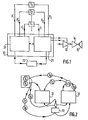
- FIGS. 1 and 2 show an anti-theft device for radio apparatus comprising a microprocessor 11 ensuring the management of a "radio" mode, symbolized by block 21, whose functions Fi are controlled by keys Ti.
- the radio apparatus comprises, inter alia, a preamplifier 12, an amplifier 14 and a loudspeaker 15.
- the microprocessor 11 also ensures the management of an "anti-theft" mode, symbolized by the block 31, whose functions F'i are controlled by the same control keys Ti.
- the "anti-theft" mode 31 consists in putting the radio device out of operation by blocking all the radio functions provided by the microprocessor 11 so as to prevent this passage from block 31 to block 21 .
- the "anti-theft" mode 31 has a locked position such that, to switch from the “anti-theft” mode 31 in the locked position to the "radio” mode 21, it is necessary to supply the microprocessor 11 with a code identical to a code previously stored in a non-volatile memory 13 associated with the microprocessor 11.
- the code stored in the non-volatile memory 13 consists of the numbers significant of a frequency modulation frequency.
- This code is supplied to the microprocessor by means of two keys T4, T5, called coding keys, which, in this case, are the scrolling keys of the frequency, up or down, of a search button d toggle broadcast. The code thus provided is validated by operating a T6 validation key.
- the other keys can be chosen from those which in “radio” mode provide the following functions: increase the volume, decrease the volume, right balance, left balance, front balance, rear balance, bass, treble, etc ...
- the keys T7, T8 for validation and storage of a new code are The keys which, in "radio” mode, allow validating and storing in memory transmission frequencies selected by the user.
Landscapes
- Engineering & Computer Science (AREA)
- Mechanical Engineering (AREA)
- Burglar Alarm Systems (AREA)
- Transceivers (AREA)
- Circuits Of Receivers In General (AREA)
- Fittings On The Vehicle Exterior For Carrying Loads, And Devices For Holding Or Mounting Articles (AREA)
Abstract
Description
- La présente invention concerne un dispositif antivol pour appareil radio comportant un microprocesseur assurant, d'une part, La aestion d'un mode "radio", et, d'autre part, La gestion d'un mode "antivol" dont les fonctions F'i sont commandées par les mêmes touches Ti de commande des fonctions Fi du mode "radio", Le passage du mode "antivol", en position verrouillée, au mode "radio" étant obtenu en fournissant au microprocesseur un code identique à un code préalablement stocké dans une mémoire non volatile associée au microprocesseur.
- L'invention trouve une application particulièrement avantageuse dans Le domaine des appareils radio pour véhicules automobiles.
- Un dispositif antivol conforme au préambule, relatif aux machines à écrire, est décrit dans IBM Technical Disclosure Bulletin (Vol. 25 No 4, 4 Septembre 1982). Ce dispositif connu pré- sente l'inconvénient que les opérations d'identification de l'utilisateur doivent être renouvelées après chaque mise sous tension de La machine sans que celle-ci ait été nécessairement volée ou déplacée, ce qui apporte des contraintes excessives en cas d'usage répété par l'utilisateur habituel ou par une personne autorisée.
- Le but de La présente invention est de proposer une procédure plus simple et mieux adaptée au problème spécifique posé.
- En effet, selon La présente invention, un dispositif antivol pour appareil radio comportant un microprocesseur assurant, d'une part, La gestion d'un mode "radio", et, d'autre part, La gestion d'un mode "antivol" dont les fonctions F'i sont commandées par les mêmes touches Ti de commande des fonctions Fi du mode "radio", Le passage du mode "antivol", en position verrouillée, au mode "radio" étant obtenu en fournissant au microprocesseur un code identique à un code préalablement stocké dans une mémoire non volatile associée au microprocesseur, est notamment remarquable en ce qu'après une coupure de l'alimentation de l'appareil radio, une remise sous tension dudit appareil provoque un accès, dit accès involontaire, au mode "antivol" en position verrouillée.
- Cette situation se produit, notamment, en cas de vol dans une voiture d'un appareil du type auto-radio. Au moment où l'appareil est volé, l'alimentation venant de La batterie est coupée, puis, si l'appareil est remis sous tension, Le microprocesseur ne fonctionnera pas en mode "radio" mais se mettra automatiquement en mode "antivol" en position verrouillée dont on ne pourra alors sortir, pour passer en mode "radio", qu'à l'aide du code susmentionné.
- En outre, il est également prévu qu'un accès, dit accès volontaire, au mode "antivol", à partir du mode "radio", est obtenu par manoeuvre simultanée d'au moins deux touches, dites touches d'accès volontaire au mode "antivol" S'il Le désire, l'utilisateur peut alors verrouiller Le mode "antivol" afin, par exemple, d'interdire à des tiers L'accès au mode "radio". Pour cela, La manoeuvre d'au moins une touche de verrouillage permet de verrouiller le mode "antivol", après accès volontaire. Le retour au mode "radio" est obtenu par fourniture du code stocké dans La mémoire non volatile de l'appareil. De même, l'utilisateur a La possibilité de changer de code. Dans ce but, après accès volontaire au mode "antivol", une manoeuvre d'une touche de programmation, suivie des manoeuvres successives de La touche de codage, et de deux touches de validation-stockage, permet de changer le code stocké dans La mémoire non volatile et de revenir au mode "radio".
- La description qui va suivre, en regard des dessins annexés donnés à titre d'exemples non Limitatifs fera bien comprendre en quoi consiste L'invention.
-
- La figure 1 est un schéma synoptique d'un dispositif antivol selon L'invention.
- La figure 2 précise Les fonctions des touches de commande dans Le mode "antivol".
- Les figures 1 et 2 montrent un dispositif antivol pour appareil radio comportant un microprocesseur 11 assurant La gestion d'un mode "radio", symbolisé par Le bloc 21, dont les fonctions Fi sont commandées par des touches Ti. L'appareiL radio comporte, entre autres, un préamplificateur 12, un amplificateur 14 et un haut- parleur 15. Comme Le montre les figures 1 et 2, le microprocesseur 11 assure également, La gestion d'un mode "antivol", symbolisé par le bloc 31, dont les fonctions F'i sont commandées par les mêmes touches Ti de commande. Dans l'exemple de réalisation montré sur la figure 1, Le mode "antivol" 31 consiste à mettre hors fonctionnement l'appareil radio en bloquant toutes les fonctions radio assurées par Le microprocesseur 11 de façon à interdire Ce passage du bloc 31 au bloc 21.
- Le mode "antivol" 31 dispose d'une position verrouillée telle que, pour passer du mode "antivol" 31 en position verrouillée au mode "radio" 21, il est nécessaire de fournir au microprocesseur 11 un code identique à un code préalablement stocké dans une mémoire non volatile 13 associée au microprocesseur 11. A titre d'exemple, lorsque l'appareil radio comporte un récepteur à modulation de fréquence et un afficheur alphanumérique de La fréquence, Le code stocké dans La mémoire non volatile 13 est constitué par les chiffres significatifs d'une fréquence de modulation de fréquence. Ce code est fourni au microprocesseur à l'aide de deux touches T4, T5, dites touches de codage, qui, dans ce cas, sont les touches-défilement de La fréquence, en montant ou en descendant, d'un bouton de recherche d'émission à basculement. Le code ainsi fourni est validé par manoeuvre d'une touche T6 de validation.
- Un accès involontaire au mode "antivol" 31 en position verrouillée se produit lorsqu'après coupure de l'alimentation de l'appareil radio, celui-ci est remis sous tension. Le microprocesseur parcourt alors Le cycle du mode "antivol" 31 et ne peut passer en mode "radio" 21 que si on lui fournit Le code stocké dans la mémoire non volatile 13.
- il est également prévu de pouvoir accéder volontairement au mode "antivol" 31, par exemple, pour verrouiller Le fonctionnement de l'appareil radio ou, encore, pour changer de code. L'accès volontaire au mode "antivol" 31, à partir du mode "radio" 21, est obtenu par manoeuvre simultanée d'au moins deux touches T1, T2, dites touches d'accès volontaire au mode "antivoL". Le mode "antivol" peut alors être verrouillé par manoeuvre d'une touche T3 de verrouillage Cette possibilité présente L'intérêt d'offrir à l'utilisateur une véritable clé interdisant L'accès de tiers au mode "radio". D'autre part, après accès volontaire au mode "antivol" 31, une manoeuvre d'une touche de programmation T9, suivie des manoeuvres successives des touches T4, T5 de codage, et de deux touches T7, T8 de validation-stockage permet de changer le code stocké dans La mémoire non volatile 13 et de revenir au mode "radio" 21. Enfin, après accès volontaire au mode "antivol" 31 il est toujours possible de revenir directement au mode "radio" 21 à l'aide d'une touche de retour T10.
- Outre Les touches T4, T5 de codage qui en mode "radio" assurent Les fonctions de défilement de La bande de fréquence, Les autres touches peuvent être choisies parmi celles qui en mode "radio" assurent Les fonctions suivantes : augmentation du volume, diminution du volume, balance droite, balance gauche, balance avant, balance arrière, grave, aigu, etc... De préférence, Les touches T7, T8 de validation-stockage d'un nouveau code sont Les touches qui, en mode "radio", permettent de valider et stocker en mémoire des fréquences d'émission sélectionnées par l'utilisateur.
- Enfin, dans le but d'empêcher un tiers de passer du mode "antivol" au mode "radio" en essayant tous les codes possibles, il est prévu qu'au bout de n (3 par exemple) retours consécutifs au mode "antivol", les touches Ti de commande sont inutilisables pendant un temps t de pénalisation, 5 mn par exemple; ce temps t de pénalisation étant ensuite renouvelé après chaque retour au mode "antivol".
Claims (7)
Applications Claiming Priority (2)
| Application Number | Priority Date | Filing Date | Title |
|---|---|---|---|
| FR8317562 | 1983-11-04 | ||
| FR8317562A FR2554665B1 (fr) | 1983-11-04 | 1983-11-04 | Dispositif antivol par microprocesseur pour appareil radio |
Publications (3)
| Publication Number | Publication Date |
|---|---|
| EP0141468A2 true EP0141468A2 (fr) | 1985-05-15 |
| EP0141468A3 EP0141468A3 (en) | 1985-06-19 |
| EP0141468B1 EP0141468B1 (fr) | 1989-05-17 |
Family
ID=9293795
Family Applications (1)
| Application Number | Title | Priority Date | Filing Date |
|---|---|---|---|
| EP84201570A Expired EP0141468B1 (fr) | 1983-11-04 | 1984-10-31 | Dispositif antivol par microprocesseur pour appareil radio |
Country Status (5)
| Country | Link |
|---|---|
| EP (1) | EP0141468B1 (fr) |
| JP (1) | JPS60113745A (fr) |
| DE (1) | DE3478272D1 (fr) |
| ES (1) | ES8600601A1 (fr) |
| FR (1) | FR2554665B1 (fr) |
Cited By (1)
| Publication number | Priority date | Publication date | Assignee | Title |
|---|---|---|---|---|
| EP0859296A1 (fr) * | 1997-02-15 | 1998-08-19 | AEG Hausgeräte GmbH | Méthode pour isoler un appareil électroménager des interventions accidentels durant les fonctionnements choisis |
Families Citing this family (12)
| Publication number | Priority date | Publication date | Assignee | Title |
|---|---|---|---|---|
| US4494114B1 (en) * | 1983-12-05 | 1996-10-15 | Int Electronic Tech | Security arrangement for and method of rendering microprocessor-controlled electronic equipment inoperative after occurrence of disabling event |
| DE3509562A1 (de) * | 1985-03-16 | 1986-09-18 | Blaupunkt-Werke Gmbh, 3200 Hildesheim | System zur sicherung von elektronischen geraeten, insbesondere autoradios gegen diebstahl |
| DE3520395C1 (de) * | 1985-06-07 | 1990-03-29 | Audi AG, 8070 Ingolstadt | Diebstahlsicherung für ein Autoradio |
| JPS6249726A (ja) * | 1985-08-29 | 1987-03-04 | Alpine Electron Inc | 車載用機器の起動方法 |
| FR2586630A1 (fr) * | 1985-09-02 | 1987-03-06 | Lopiccolo Joseph | Dispositif antivol, par dissuasion, pour autoradio |
| JPS62105738A (ja) * | 1985-11-01 | 1987-05-16 | Clarion Co Ltd | 車載用音響機器の盗難防止装置 |
| IT207767Z2 (it) * | 1986-05-13 | 1988-02-15 | Fiat Auto Spa | Autoveicolo provvisto di plancia con radioricevitore incorporato econ sede per mangianastri estraibile e personalizzabile |
| FR2634334A1 (fr) * | 1988-07-12 | 1990-01-19 | Radiotechnique Ind & Comm | Dispositif de commande logique de commutation de l'alimentation d'un autoradio |
| JPH03118250A (ja) * | 1989-09-29 | 1991-05-20 | Pioneer Electron Corp | 車載電気機器の盗難対策装置 |
| JPH02306839A (ja) * | 1990-01-22 | 1990-12-20 | Clarion Co Ltd | 車載用音響機器の盗難防止装置 |
| DE4008031A1 (de) * | 1990-03-14 | 1991-09-19 | Vdo Schindling | Anordnung zur messung einer fluessigkeitsmenge |
| DE19708314A1 (de) * | 1997-02-28 | 1998-09-03 | Volkswagen Ag | Vorrichtung und Verfahren zur Diebstahlsicherung von Zusatzgeräten |
Family Cites Families (5)
| Publication number | Priority date | Publication date | Assignee | Title |
|---|---|---|---|---|
| JPS5715743B2 (fr) * | 1974-11-18 | 1982-04-01 | ||
| FR2448077A1 (fr) * | 1979-02-05 | 1980-08-29 | Pont A Mousson | Dispositif de commande des changements de rapports d'une boite de vitesses |
| DE3104668A1 (de) * | 1981-02-10 | 1982-09-02 | Siemens AG, 1000 Berlin und 8000 München | Multifunktionsbedienteil |
| JPS5835694A (ja) * | 1981-08-26 | 1983-03-02 | 日産自動車株式会社 | 自動車用盗難防止制御装置 |
| IT1154412B (it) * | 1982-01-08 | 1987-01-21 | Fiat Auto Spa | Dispositivo radioricebitore e di controllo di parametri di viaggio di un autoveicolo |
-
1983
- 1983-11-04 FR FR8317562A patent/FR2554665B1/fr not_active Expired
-
1984
- 1984-10-31 DE DE8484201570T patent/DE3478272D1/de not_active Expired
- 1984-10-31 ES ES537266A patent/ES8600601A1/es not_active Expired
- 1984-10-31 EP EP84201570A patent/EP0141468B1/fr not_active Expired
- 1984-11-01 JP JP59229039A patent/JPS60113745A/ja active Pending
Cited By (2)
| Publication number | Priority date | Publication date | Assignee | Title |
|---|---|---|---|---|
| EP0859296A1 (fr) * | 1997-02-15 | 1998-08-19 | AEG Hausgeräte GmbH | Méthode pour isoler un appareil électroménager des interventions accidentels durant les fonctionnements choisis |
| EP0859296B1 (fr) * | 1997-02-15 | 2004-01-28 | AEG Hausgeräte GmbH | Méthode pour isoler un appareil électroménager des interventions accidentelles durant les fonctionnements choisis |
Also Published As
| Publication number | Publication date |
|---|---|
| JPS60113745A (ja) | 1985-06-20 |
| DE3478272D1 (en) | 1989-06-22 |
| ES537266A0 (es) | 1985-09-16 |
| FR2554665B1 (fr) | 1986-07-25 |
| ES8600601A1 (es) | 1985-09-16 |
| FR2554665A1 (fr) | 1985-05-10 |
| EP0141468B1 (fr) | 1989-05-17 |
| EP0141468A3 (en) | 1985-06-19 |
Similar Documents
| Publication | Publication Date | Title |
|---|---|---|
| EP0141468B1 (fr) | Dispositif antivol par microprocesseur pour appareil radio | |
| US4683462A (en) | Device for protecting audio equipment in vehicle against theft | |
| EP0629758B1 (fr) | Système de télécommande à plusieurs portées fonctionnelles sélectionnées par seuil de détection | |
| US4598562A (en) | Steering column protective jacket | |
| US5752416A (en) | Retaining device for a bicycle | |
| FR2754091A1 (fr) | Telecommande rf double portee pour vehicule automobile | |
| FR2781445A1 (fr) | Dispositif de controle d'acces pour vehicule automobile et procede de reglage de la sensibilite de ce dispositif | |
| US5742226A (en) | Simple theft deterrent for electronic control modules | |
| FR2669368A1 (fr) | Serrure electronique et mecanique et cle pour une telle serrure. | |
| EP0595402B1 (fr) | Récepteur de radio pour véhicule automobile, muni d'une partie amovible comportant des fonctions essentielles du récepteur | |
| FR2751293A1 (fr) | Dispositif antivol pour motocycle et casque de protection motocycliste | |
| FR2589405A1 (fr) | Dispositif antivol pour appareil audio | |
| EP3127792B1 (fr) | Système d'authentification de véhicule monté à califourchon et un tel véhicule | |
| US5899100A (en) | Transmission lock device | |
| EP0822695B1 (fr) | Téléphone avec mode de fonctionnement restreint | |
| US5323139A (en) | Antitheft system for a car stereo having a detachable grille | |
| FR2729349A1 (fr) | Installation de securite pour vehicule automobile | |
| FR2720703A1 (fr) | Système antivol de véhicule. | |
| EP1504986B1 (fr) | Système pour démarrer un véhicule motorisé | |
| US6542069B1 (en) | Method of protecting components connected to a car radio | |
| FR2719962A1 (fr) | Dispositif électronique de sécurité et procédé pour son fonctionnement. | |
| US5983681A (en) | Lock device for an automatic shift lever | |
| FR2755420A1 (fr) | Systeme a emetteur et recepteur, notamment pour la commande electrique du derailleur d'un cycle | |
| EP0646506B1 (fr) | Procédé de contrÔle d'un organe antivol de véhicule avec système d'accès par commande à distance, et moyen antivol ainsi constitué | |
| EP1043205B1 (fr) | Système d'accès à un véhicule automobile, équipé d'un dispositif d'identification et d'un identifiant à télécommande |
Legal Events
| Date | Code | Title | Description |
|---|---|---|---|
| PUAI | Public reference made under article 153(3) epc to a published international application that has entered the european phase |
Free format text: ORIGINAL CODE: 0009012 |
|
| PUAL | Search report despatched |
Free format text: ORIGINAL CODE: 0009013 |
|
| AK | Designated contracting states |
Designated state(s): DE FR GB IT NL |
|
| AK | Designated contracting states |
Designated state(s): DE FR GB IT NL |
|
| 17P | Request for examination filed |
Effective date: 19851218 |
|
| 17Q | First examination report despatched |
Effective date: 19870209 |
|
| GRAA | (expected) grant |
Free format text: ORIGINAL CODE: 0009210 |
|
| AK | Designated contracting states |
Kind code of ref document: B1 Designated state(s): DE FR GB IT NL |
|
| PG25 | Lapsed in a contracting state [announced via postgrant information from national office to epo] |
Ref country code: NL Effective date: 19890517 |
|
| REF | Corresponds to: |
Ref document number: 3478272 Country of ref document: DE Date of ref document: 19890622 |
|
| ITF | It: translation for a ep patent filed | ||
| GBT | Gb: translation of ep patent filed (gb section 77(6)(a)/1977) | ||
| RAP2 | Party data changed (patent owner data changed or rights of a patent transferred) |
Owner name: N.V. PHILIPS' GLOEILAMPENFABRIEKEN Owner name: LA RADIOTECHNIQUE PORTENSEIGNE |
|
| NLV1 | Nl: lapsed or annulled due to failure to fulfill the requirements of art. 29p and 29m of the patents act | ||
| PLBE | No opposition filed within time limit |
Free format text: ORIGINAL CODE: 0009261 |
|
| STAA | Information on the status of an ep patent application or granted ep patent |
Free format text: STATUS: NO OPPOSITION FILED WITHIN TIME LIMIT |
|
| 26N | No opposition filed | ||
| REG | Reference to a national code |
Ref country code: FR Ref legal event code: CD |
|
| PGFP | Annual fee paid to national office [announced via postgrant information from national office to epo] |
Ref country code: GB Payment date: 19910930 Year of fee payment: 8 |
|
| ITTA | It: last paid annual fee | ||
| PGFP | Annual fee paid to national office [announced via postgrant information from national office to epo] |
Ref country code: DE Payment date: 19911223 Year of fee payment: 8 |
|
| PG25 | Lapsed in a contracting state [announced via postgrant information from national office to epo] |
Ref country code: GB Effective date: 19921031 |
|
| GBPC | Gb: european patent ceased through non-payment of renewal fee |
Effective date: 19921031 |
|
| PG25 | Lapsed in a contracting state [announced via postgrant information from national office to epo] |
Ref country code: DE Effective date: 19930701 |
|
| PGFP | Annual fee paid to national office [announced via postgrant information from national office to epo] |
Ref country code: FR Payment date: 19941026 Year of fee payment: 11 |
|
| PG25 | Lapsed in a contracting state [announced via postgrant information from national office to epo] |
Ref country code: FR Effective date: 19960628 |
|
| REG | Reference to a national code |
Ref country code: FR Ref legal event code: ST |