EP0141541A2 - Procédé de fabrication d'une lentille de contact et dispositif pour la mise en oeuvre du procédé - Google Patents
Procédé de fabrication d'une lentille de contact et dispositif pour la mise en oeuvre du procédé Download PDFInfo
- Publication number
- EP0141541A2 EP0141541A2 EP84306811A EP84306811A EP0141541A2 EP 0141541 A2 EP0141541 A2 EP 0141541A2 EP 84306811 A EP84306811 A EP 84306811A EP 84306811 A EP84306811 A EP 84306811A EP 0141541 A2 EP0141541 A2 EP 0141541A2
- Authority
- EP
- European Patent Office
- Prior art keywords
- blank
- work holder
- face
- hole
- machine tool
- Prior art date
- Legal status (The legal status is an assumption and is not a legal conclusion. Google has not performed a legal analysis and makes no representation as to the accuracy of the status listed.)
- Granted
Links
- 238000000034 method Methods 0.000 title claims abstract description 13
- 238000004519 manufacturing process Methods 0.000 title claims abstract description 10
- 238000003754 machining Methods 0.000 claims abstract description 9
- 239000000463 material Substances 0.000 claims description 17
- 238000001816 cooling Methods 0.000 claims description 6
- 210000005252 bulbus oculi Anatomy 0.000 claims description 4
- 239000012768 molten material Substances 0.000 claims 1
- 230000000712 assembly Effects 0.000 description 5
- 238000000429 assembly Methods 0.000 description 5
- 239000004033 plastic Substances 0.000 description 3
- 229920003023 plastic Polymers 0.000 description 3
- 230000004438 eyesight Effects 0.000 description 2
- 210000000887 face Anatomy 0.000 description 2
- 239000002184 metal Substances 0.000 description 2
- 150000001875 compounds Chemical class 0.000 description 1
- 238000007796 conventional method Methods 0.000 description 1
- 238000005520 cutting process Methods 0.000 description 1
- 230000007812 deficiency Effects 0.000 description 1
- 229910003460 diamond Inorganic materials 0.000 description 1
- 239000010432 diamond Substances 0.000 description 1
- 230000036571 hydration Effects 0.000 description 1
- 238000006703 hydration reaction Methods 0.000 description 1
- 238000003303 reheating Methods 0.000 description 1
- 229920001169 thermoplastic Polymers 0.000 description 1
- 239000004416 thermosoftening plastic Substances 0.000 description 1
Images

Classifications
-
- B—PERFORMING OPERATIONS; TRANSPORTING
- B24—GRINDING; POLISHING
- B24B—MACHINES, DEVICES, OR PROCESSES FOR GRINDING OR POLISHING; DRESSING OR CONDITIONING OF ABRADING SURFACES; FEEDING OF GRINDING, POLISHING, OR LAPPING AGENTS
- B24B13/00—Machines or devices designed for grinding or polishing optical surfaces on lenses or surfaces of similar shape on other work; Accessories therefor
- B24B13/005—Blocking means, chucks or the like; Alignment devices
-
- B—PERFORMING OPERATIONS; TRANSPORTING
- B29—WORKING OF PLASTICS; WORKING OF SUBSTANCES IN A PLASTIC STATE IN GENERAL
- B29D—PRODUCING PARTICULAR ARTICLES FROM PLASTICS OR FROM SUBSTANCES IN A PLASTIC STATE
- B29D11/00—Producing optical elements, e.g. lenses or prisms
- B29D11/00932—Combined cutting and grinding thereof
Definitions
- This invention relates to a method of manufacturing a contact lens, and to apparatus for use in carrying out the method.
- Contact lenses worn by a user instead of conventional lenses carried by a frame to correct eyesight deficiencies, are manufactured from plastics materials which in a lens as worn can be hard, soft, or gas permeable.
- Such lenses have to be manufactured to a very high degree of accuracy if they are to be useful in providing desired eyesight correction.
- a conventional method of manufacturing a contact lens is to machine a blank of suitable material, for example a right circular cylinder-some 4mm long and 12.7 mm in diameter, to produce from one of the major surfaces of the blank, a face shaped for contact with a user's eyeball.
- suitable material for example a right circular cylinder-some 4mm long and 12.7 mm in diameter
- a carrier mounted for rotation on a spindle of a machine tool is heated and a thermoplastic pitch material applied thereto to produce a body of warm pliable material to which the blank is applied with the shaped face of the blank in contact with warm pliable material.
- the blank Before the warm pliable material cools and sets the blank must be accurately aligned with its longitudinal axis in line with the axis of rotation of the machine tool spindle and with its free major surface perpendicular to that axis. This is achieved by the operator manufacturing the contact lens engaging the blank in a V-shaped notch in a metal bar while the blank is being rotated on the machine tool spindle, the bar being used to urge the blank into the best aligned position possible such position being that in which movement of the metal bar caused by its engagement with the rotating blank is a minimum.
- the carrier with the blank mounted thereon must be removed from the machine tool spindle and reheated to soften the mounting material again, the carrier then being returned to the machine tool spindle for further alignment of the blank.
- This removal of the carrier for reheating with subsequent replacement for alignment of the blank may have to be carried out many times before satisfactory alignment of the blank is achieved.
- the blank is machined on the machine tool to produce a required lens.
- a further disadvantage of the known method discussed above is that on cooling of the initially warm pliable mounting material on which the blank has been aligned, the blank may be caused to tilt on the carrier such that the previously machined face is no longer correctly positioned relative to the axis of rotation of the machine tool spindle. This will result in the contact lens then produced by further machining of the blank, having inherent prismatic problems due to the incorrect relative alignment of its two machined faces.
- a method of manufacturing a contact lens comprises machining a blank to produce thereon a first face shaped for contact with a user's eyeball, and a reference surface accurately spaced a predetermined distance from said first face; mounting the blank on a work holder with a second face of the blank opposite to said first face exposed, the work holder being adapted for accurate mounting on a machine tool and having a part engaged by said reference surface of the blank whereby the work holder holds the blank with said first face accurately positioned relative to a datum point of the machine tool; and machining said second face of the blank held by the work holder on the machine tool to produce a required contact lens.
- the blank is initially in the form of a right circular cylinder and is initially machined to produce said first face from one end surface of the blank and said reference surface as an annular surface facing the same way as said first face and spaced therefrom by a portion of reduced diameter.
- Such a machined blank can be mounted on the work holder by receipt of the reduced diameter portion of the blank as a close fit in a hole in the work holder with said reference surface of the blank in engagement with a rim of the hole whereby said first face of the blank is accurately positioned relative to and within the hole in the work holder.
- a molten wax or similar material can then be introduced into the hole in the work holder and into contact with said first face of the blank, which material after cooling and setting will serve to secure the blank to the work holder while said second face of the blank is machined, the material being cooled or soaked to release a completed contact lens from the work holder.
- the work holder has a surface accurately located a predetermined distance from the rim of the hole in the work holder, which surface serves as said datum point of the machine tool when the work holder is mounted thereon.
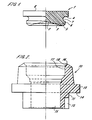
- this shows an intermediate blank 1 machined from a standard blank used in the manufacture of contact lenses, such a standard blank being a right circular cylinder of plastics material 4mm long and 12.7 mm in diameter.
- one end surface of the blank 1 has been machined to produce a first concave compound curve face 2,3 shaped for contact with the eyeball of a person using the contact lens manufactured from the blank 1.
- the blank 1 also has an annular reference surface 4 facing the same way as the first face 2,3, and accurately spaced a predetermined distance therefrom by a portion 5 of reduced diameter having a cylindrical outer surface 6.
- the surface 6 is separated from the reference surface 4 by an arcuate recess 7 the purpose of which will be described later.
- the other end surface of the blank 1 is left as a circular second face 8.
- Figure 2 shows a work holder lO formed of plastics material adapted to hold a blank 1 as shown in Figure 1 and to be accurately mounted on a machine tool, for example a lathe as mentioned above.
- the work holder 10 has at one end a cylindrical mounting portion 11 which can be gripped in the chuck of a lathe as mentioned above, the mounting portion 11 being formed with a recess 12 in which a part of the chuck engages to prevent rotation of the work holder 10 relative to the chuck during machining of a blank held in the work holder 10.
- the inner end of the mounting portion 11 is defined by a flange 13 having a surface 14 facing the free end of the mounting portion 11, which surface 14 serves for accurate location of the work holder lO in the machine tool chuck.
- the work holder 10 is formed with a through hole 15 which terminates at the other end of the work holder remote from the mounting portion 11 with a rim 16.
- the hole 15 Inwardly of the rim 16 the hole 15 has a cylindrical section 17 sized to receive as a close fit the cylindrical surface 6 of the portion 5 of the blank 1 shown in Figure 1.
- the surface 18 of the hole 15 between the section 17 and the rim 16 is belled for a purpose which will be described later.
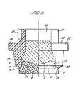
- FIG 3 shows a blank 1 as shown in Figure 1 mounted in the work holder 10 of Figure 2.
- the portion 5 of the blank 1 is received in the section 17 of the hole 15 in the work holder 10, and the blank 1 is positioned with its reference surface 4 in engagement with the rim 16 on the work holder 10.
- the recess 7 in the blank 1 and the belled surface 18 of the hole 15 in the work holder 10 serve to ensure clearance between the blank and the work holder other than for the engagement between the reference surface 4 of the blank 1 and the rim 16 of the work holder 10, and between the surface 6 of the blank 1 and the surface 17 of the hole 15 in the work holder 10, thus helping to ensure accurate location of the blank in the work holder.
- the work holder 10 is manufactured such that the surface 14 of the flange 13 is accurately located a predetermined distance from the rim 16 of the hole 15 in the work holder 10, and thus with the blank 1 mounted in the work holder 10 as shown in Figure 3, the face 2,3 of the blank 1 is accurately located relative to the surface 14 of the work holder 10. Since the surface 14 of the work holder 10 also serves for accurate location of the work holder 10 on the machine tool, then the surface 14 serves as a datum point of the machine tool relative to the first surface 2,3 of the blank 1.
- the second face 8 of the blank 1 can be machined to produce a required contact lens, the final thickness of the contact lens being determined from the machine tool without the need for using any separate thickness gauge. Further, since the blank 1 is accurately located by the work holder 10 at all times there is no possibility of titling of the blank 1 and thus prismatic problems are avoided.
- the completed contact lens- is held by wax 20 and is released from the work holder 10 by cooling the work holder 10, for example in a refrigerator, or if a hydrophilic contact lens is being produced by the subsequent hydration operation.
- the jig arrangement comprises a circular base board 30 having its upper surface covered with a layer 31 of sponge material. Upstanding from the centre of the base board 30 is a bolt 32 carrying a nut 33 which can be screwed down towards the base board 30. Mounted on the bolt 32 beneath the nut 33 is a pressure board 34, shown in plan view in Figure 5, formed with a plurality of holes 35 each to receive the mounting portion 11 of a work holder as shown in Figure 2 but not pass the flange 13 of the work holder 10.
- a plurality of assemblies each comprising a blank 1 as shown in Figure 1 mounted in a work holder 10 as shown in Figure 2 are then mounted between the pressure board 34 and base board 30, as shown in Figure 4-with the blanks 1 in contact with the sponge layer 31, and the nut 33 is then tightened down to compress the assemblies between the boards 30 and 34 thereby to retain the blanks 1 accurately mounted on their respective work holders 10.
- Hot wax 20 ( Figure 3) is then introduced into the hole 15 in each of the work holders 10, and after cooling of the wax to secure the blanks 1 to their work holders 10 the nut 33 is released and the assemblies removed from the jig for mounting on the machine tool.
Landscapes
- Engineering & Computer Science (AREA)
- Mechanical Engineering (AREA)
- Health & Medical Sciences (AREA)
- Manufacturing & Machinery (AREA)
- Ophthalmology & Optometry (AREA)
- Eyeglasses (AREA)
- Grinding And Polishing Of Tertiary Curved Surfaces And Surfaces With Complex Shapes (AREA)
- Casting Or Compression Moulding Of Plastics Or The Like (AREA)
- Jigs For Machine Tools (AREA)
Priority Applications (1)
| Application Number | Priority Date | Filing Date | Title |
|---|---|---|---|
| AT84306811T ATE46845T1 (de) | 1983-10-24 | 1984-10-05 | Verfahren zum herstellen einer kontaktlinse und vorrichtung zur verwertung des verfahrens. |
Applications Claiming Priority (2)
| Application Number | Priority Date | Filing Date | Title |
|---|---|---|---|
| GB08328365A GB2148169B (en) | 1983-10-24 | 1983-10-24 | Method of manufacturing a contact lens and apparatus for use in the method |
| GB8328365 | 1983-10-24 |
Publications (3)
| Publication Number | Publication Date |
|---|---|
| EP0141541A2 true EP0141541A2 (fr) | 1985-05-15 |
| EP0141541A3 EP0141541A3 (en) | 1986-12-03 |
| EP0141541B1 EP0141541B1 (fr) | 1989-10-04 |
Family
ID=10550645
Family Applications (1)
| Application Number | Title | Priority Date | Filing Date |
|---|---|---|---|
| EP84306811A Expired EP0141541B1 (fr) | 1983-10-24 | 1984-10-05 | Procédé de fabrication d'une lentille de contact et dispositif pour la mise en oeuvre du procédé |
Country Status (6)
| Country | Link |
|---|---|
| US (1) | US4619082A (fr) |
| EP (1) | EP0141541B1 (fr) |
| JP (1) | JPS60125652A (fr) |
| AT (1) | ATE46845T1 (fr) |
| DE (1) | DE3479972D1 (fr) |
| GB (1) | GB2148169B (fr) |
Cited By (3)
| Publication number | Priority date | Publication date | Assignee | Title |
|---|---|---|---|---|
| GB2230983A (en) * | 1989-05-05 | 1990-11-07 | Gilco Optics Limited | Lens blank mountings |
| GB2287421A (en) * | 1994-03-04 | 1995-09-20 | Hydron Ltd | Process of preparing lenses |
| WO1996012590A1 (fr) * | 1994-10-19 | 1996-05-02 | Rank Taylor Hobson Limited | Procede in-situ et appareil de blocage de lentilles de contact |
Families Citing this family (20)
| Publication number | Priority date | Publication date | Assignee | Title |
|---|---|---|---|---|
| US5007975A (en) * | 1986-11-13 | 1991-04-16 | Menicon Co., Ltd. | Ultraviolet-hardenable adhesive and bonding method employing same |
| US5145884A (en) * | 1986-11-13 | 1992-09-08 | Menicon Co., Ltd. | Ultraviolet-hardenable adhesive |
| US5009731A (en) * | 1989-10-25 | 1991-04-23 | Menicon Co., Ltd. | Ultraviolet-hardenable adhesive and bonding method employing same |
| US5181053A (en) * | 1990-05-10 | 1993-01-19 | Contact Lens Corporation Of America | Multi-focal contact lens |
| WO1994009946A1 (fr) * | 1992-10-26 | 1994-05-11 | D.A.C., Inc. | Systeme de blocage de lentille et d'epaisseur centrale constante |
| US5494474A (en) * | 1991-03-27 | 1996-02-27 | D.A.C., Inc. | Lens blocking and constant center thickness system |
| US5474489A (en) * | 1991-03-27 | 1995-12-12 | D.A.C., Inc. | Lens blocking and constant center thickness system |
| US5205076A (en) * | 1991-03-27 | 1993-04-27 | Development Associates Controls, Inc. | Self-aligned lens manufacturing system and method |
| US5380387A (en) * | 1992-10-13 | 1995-01-10 | Loctite Corporation | Lens blocking/deblocking method |
| EP1436119B2 (fr) * | 2001-10-17 | 2008-08-13 | Schneider GmbH + Co. KG | Dispositif et procede pour l'usinage complet de lentilles optiquement actives sur les deux faces |
| IL152834A (en) * | 2002-11-14 | 2008-11-26 | Shamir Special Optical Product | Lens production method and process |
| US7121931B2 (en) * | 2002-11-14 | 2006-10-17 | Kti Technologies Ltd. | Lens production method and process |
| US7011571B2 (en) | 2003-10-02 | 2006-03-14 | Radtek Corporation | Blocking apparatus for lens manufacturing including automatic wax delivery system |
| US7059037B2 (en) | 2003-10-02 | 2006-06-13 | Radtek Corporation | Blocking apparatus providing an adjustable offset for precision alignment |
| US20050075060A1 (en) * | 2003-10-02 | 2005-04-07 | Konrad Bergandy | Apparatus for precision alignment during blocking process of lens manufacturing |
| US7187859B2 (en) * | 2004-12-06 | 2007-03-06 | Paragon Vision Sciences, Inc. | Method and apparatus for manufacturing contact lenses |
| US20060117919A1 (en) * | 2004-12-06 | 2006-06-08 | Hank Stute | Method and apparatus for manufacturing contact lenses |
| US8871317B2 (en) * | 2010-09-09 | 2014-10-28 | Teknor Apex Company | Curable adhesive system, method of assembly of distinct components therewith |
| US20130303060A1 (en) * | 2010-11-26 | 2013-11-14 | Schneider Gmbh & Co. Kg | Block piece |
| GB2639434A (en) * | 2022-10-28 | 2025-09-24 | Coopervision Int Ltd | Mandrel for use in the machining of ophthalmic lenses |
Family Cites Families (7)
| Publication number | Priority date | Publication date | Assignee | Title |
|---|---|---|---|---|
| US1911153A (en) * | 1929-12-28 | 1933-05-23 | American Optical Corp | Process of blocking ophthalmic lenses |
| US3030859A (en) * | 1959-05-25 | 1962-04-24 | Jr Daniel O Elliott | Method of making contact lenses |
| US3100955A (en) * | 1960-04-25 | 1963-08-20 | Plastic Contact Lens Company | Apparatus for producing contact lenses |
| US3064531A (en) * | 1960-05-31 | 1962-11-20 | Giles E Bullock | Process for forming contact lenses |
| US3333369A (en) * | 1964-07-08 | 1967-08-01 | William R Barr | Apparatus for mounting plastic lens for grinding |
| US3662040A (en) * | 1970-01-08 | 1972-05-09 | Uroptics International Inc | Technique for lathe grinding multifocal contact lenses |
| EP0035317A1 (fr) * | 1980-03-04 | 1981-09-09 | Yoshiaki Nagaura | Procédé pour la fabrication d'articles en forme de lentille |
-
1983
- 1983-10-24 GB GB08328365A patent/GB2148169B/en not_active Expired
-
1984
- 1984-10-05 EP EP84306811A patent/EP0141541B1/fr not_active Expired
- 1984-10-05 DE DE8484306811T patent/DE3479972D1/de not_active Expired
- 1984-10-05 AT AT84306811T patent/ATE46845T1/de not_active IP Right Cessation
- 1984-10-23 JP JP59221375A patent/JPS60125652A/ja active Pending
- 1984-10-23 US US06/663,780 patent/US4619082A/en not_active Expired - Fee Related
Cited By (5)
| Publication number | Priority date | Publication date | Assignee | Title |
|---|---|---|---|---|
| GB2230983A (en) * | 1989-05-05 | 1990-11-07 | Gilco Optics Limited | Lens blank mountings |
| GB2287421A (en) * | 1994-03-04 | 1995-09-20 | Hydron Ltd | Process of preparing lenses |
| GB2287421B (en) * | 1994-03-04 | 1997-09-03 | Hydron Ltd | Process of preparing lenses |
| WO1996012590A1 (fr) * | 1994-10-19 | 1996-05-02 | Rank Taylor Hobson Limited | Procede in-situ et appareil de blocage de lentilles de contact |
| US5794498A (en) * | 1994-10-19 | 1998-08-18 | Taylor Hobson Limited | In-situ method and apparatus for blocking lenses |
Also Published As
| Publication number | Publication date |
|---|---|
| EP0141541A3 (en) | 1986-12-03 |
| EP0141541B1 (fr) | 1989-10-04 |
| GB8328365D0 (en) | 1983-11-23 |
| DE3479972D1 (en) | 1989-11-09 |
| GB2148169A (en) | 1985-05-30 |
| US4619082A (en) | 1986-10-28 |
| GB2148169B (en) | 1987-05-28 |
| JPS60125652A (ja) | 1985-07-04 |
| ATE46845T1 (de) | 1989-10-15 |
Similar Documents
| Publication | Publication Date | Title |
|---|---|---|
| EP0141541B1 (fr) | Procédé de fabrication d'une lentille de contact et dispositif pour la mise en oeuvre du procédé | |
| US4856234A (en) | Optical lens manufacturing apparatus and method | |
| US7614742B2 (en) | Method for producing ophthalmic lenses and other shaped bodies with optically active surfaces | |
| US20050020186A1 (en) | Device and method for complete machining of lenses that are optically active on two sides | |
| US4089102A (en) | Method of forming and using a lens holder | |
| JPH0671547A (ja) | 眼鏡レンズの製造方法及び装置 | |
| US5003678A (en) | Method of making a channel set ring | |
| US5085013A (en) | Contact lens orientation method and apparatus | |
| US5205076A (en) | Self-aligned lens manufacturing system and method | |
| US4388848A (en) | Cutter ring and method of making same | |
| US7121931B2 (en) | Lens production method and process | |
| US5794498A (en) | In-situ method and apparatus for blocking lenses | |
| US7125117B2 (en) | Opthalmic lens preform | |
| US1952373A (en) | Lens blocking device | |
| US3152427A (en) | Lens blank and block unit | |
| US4267672A (en) | Lens processing method | |
| US5330203A (en) | Method of generating a toric surface on a molding tool | |
| US4341045A (en) | Adapter chuck for mounting lens blanks | |
| KR20030078861A (ko) | 안경렌즈 가공방법 및 장치 | |
| US3815294A (en) | Method for making one-piece multifocal lenses | |
| EP3013566B1 (fr) | Procédés de fabrication et appareil utiles en fabrication de lentilles de contact toriques | |
| US6997046B2 (en) | Method and apparatus for fixtured wax and trace | |
| US3381356A (en) | Apparatus for supporting rotary work holder | |
| US3968599A (en) | Lens blocking tools | |
| IL152834A (en) | Lens production method and process |
Legal Events
| Date | Code | Title | Description |
|---|---|---|---|
| PUAI | Public reference made under article 153(3) epc to a published international application that has entered the european phase |
Free format text: ORIGINAL CODE: 0009012 |
|
| AK | Designated contracting states |
Designated state(s): AT BE CH DE FR IT LI LU NL SE |
|
| PUAL | Search report despatched |
Free format text: ORIGINAL CODE: 0009013 |
|
| AK | Designated contracting states |
Kind code of ref document: A3 Designated state(s): AT BE CH DE FR IT LI LU NL SE |
|
| RAP1 | Party data changed (applicant data changed or rights of an application transferred) |
Owner name: OPTICAL HOLDINGS LIMITED |
|
| 17P | Request for examination filed |
Effective date: 19870319 |
|
| 17Q | First examination report despatched |
Effective date: 19880108 |
|
| GRAA | (expected) grant |
Free format text: ORIGINAL CODE: 0009210 |
|
| RAP1 | Party data changed (applicant data changed or rights of an application transferred) |
Owner name: EMI-MEC LIMITED |
|
| AK | Designated contracting states |
Kind code of ref document: B1 Designated state(s): AT BE CH DE FR IT LI LU NL SE |
|
| PG25 | Lapsed in a contracting state [announced via postgrant information from national office to epo] |
Ref country code: NL Effective date: 19891004 Ref country code: BE Effective date: 19891004 Ref country code: AT Effective date: 19891004 |
|
| REF | Corresponds to: |
Ref document number: 46845 Country of ref document: AT Date of ref document: 19891015 Kind code of ref document: T |
|
| ITF | It: translation for a ep patent filed | ||
| PG25 | Lapsed in a contracting state [announced via postgrant information from national office to epo] |
Ref country code: LU Free format text: LAPSE BECAUSE OF NON-PAYMENT OF DUE FEES Effective date: 19891031 |
|
| REF | Corresponds to: |
Ref document number: 3479972 Country of ref document: DE Date of ref document: 19891109 |
|
| ET | Fr: translation filed | ||
| NLV1 | Nl: lapsed or annulled due to failure to fulfill the requirements of art. 29p and 29m of the patents act | ||
| PLBE | No opposition filed within time limit |
Free format text: ORIGINAL CODE: 0009261 |
|
| STAA | Information on the status of an ep patent application or granted ep patent |
Free format text: STATUS: NO OPPOSITION FILED WITHIN TIME LIMIT |
|
| 26N | No opposition filed | ||
| PGFP | Annual fee paid to national office [announced via postgrant information from national office to epo] |
Ref country code: SE Payment date: 19901030 Year of fee payment: 7 |
|
| ITTA | It: last paid annual fee | ||
| PGFP | Annual fee paid to national office [announced via postgrant information from national office to epo] |
Ref country code: CH Payment date: 19901108 Year of fee payment: 7 |
|
| PG25 | Lapsed in a contracting state [announced via postgrant information from national office to epo] |
Ref country code: SE Effective date: 19911006 |
|
| PGFP | Annual fee paid to national office [announced via postgrant information from national office to epo] |
Ref country code: FR Payment date: 19911017 Year of fee payment: 8 |
|
| PG25 | Lapsed in a contracting state [announced via postgrant information from national office to epo] |
Ref country code: LI Effective date: 19911031 Ref country code: CH Effective date: 19911031 |
|
| REG | Reference to a national code |
Ref country code: CH Ref legal event code: PL |
|
| PG25 | Lapsed in a contracting state [announced via postgrant information from national office to epo] |
Ref country code: FR Effective date: 19930630 |
|
| REG | Reference to a national code |
Ref country code: FR Ref legal event code: ST |
|
| PGFP | Annual fee paid to national office [announced via postgrant information from national office to epo] |
Ref country code: DE Payment date: 19931109 Year of fee payment: 10 |
|
| EUG | Se: european patent has lapsed |
Ref document number: 84306811.5 Effective date: 19920510 |
|
| PG25 | Lapsed in a contracting state [announced via postgrant information from national office to epo] |
Ref country code: DE Effective date: 19950701 |