EP0141552A2 - Arbeitsplattform - Google Patents
Arbeitsplattform Download PDFInfo
- Publication number
- EP0141552A2 EP0141552A2 EP84306932A EP84306932A EP0141552A2 EP 0141552 A2 EP0141552 A2 EP 0141552A2 EP 84306932 A EP84306932 A EP 84306932A EP 84306932 A EP84306932 A EP 84306932A EP 0141552 A2 EP0141552 A2 EP 0141552A2
- Authority
- EP
- European Patent Office
- Prior art keywords
- boom
- booms
- access equipment
- lower boom
- equipment according
- Prior art date
- Legal status (The legal status is an assumption and is not a legal conclusion. Google has not performed a legal analysis and makes no representation as to the accuracy of the status listed.)
- Granted
Links
- 230000003028 elevating effect Effects 0.000 claims description 5
- 239000012530 fluid Substances 0.000 claims description 3
- 230000000694 effects Effects 0.000 description 3
- 230000005484 gravity Effects 0.000 description 1
- 238000000034 method Methods 0.000 description 1
- 230000003068 static effect Effects 0.000 description 1
Images

Classifications
-
- B—PERFORMING OPERATIONS; TRANSPORTING
- B66—HOISTING; LIFTING; HAULING
- B66F—HOISTING, LIFTING, HAULING OR PUSHING, NOT OTHERWISE PROVIDED FOR, e.g. DEVICES WHICH APPLY A LIFTING OR PUSHING FORCE DIRECTLY TO THE SURFACE OF A LOAD
- B66F11/00—Lifting devices specially adapted for particular uses not otherwise provided for
- B66F11/04—Lifting devices specially adapted for particular uses not otherwise provided for for movable platforms or cabins, e.g. on vehicles, permitting workmen to place themselves in any desired position for carrying out required operations
- B66F11/044—Working platforms suspended from booms
- B66F11/046—Working platforms suspended from booms of the telescoping type
Definitions
- the invention is concerned with access equipment by means of which access is gained to elevated locations. More particularly, it is concerned with such access equipment in which a working platform or other load is mounted upon the upper or uppermost of two or more articulated booms and is moved to a desired elevated location by angular movement of the booms about horizontal axes.
- a constant search among designers of access equipment of this type is for methods of extending the height of reach and/or the lateral extent of reach (the "outreach") of such equipment while maintaining the overall stability of the structure without, if possible, increasing the area of the equipment base.
- the greater the outreach beyond the limits of the base the greater is the need to provide a counter-balancing force, in terms either of base weight or of the angle at which the lower boom is set.
- the access equipment according to the present invention is characterised by two features, namely:-
- the elevating of the booms and if desired the extending thereof may be carried out in conventional manner by the use of hydraulic rams.
- the interlocking of the various movements to ensure that the upper boom or booms cannot be moved until the lower boom is set may be achieved mechanically and/or hydraulically, although electronic inter-locking is an acceptable alternative if desired.
- the action of the ram which effects elevation of the lower boom may operate a release valve which permits hydraulic fluid to flow to the controls effecting the movements of the other boom or booms.
- the lower boom may be required to be elevated to its position of maximum height before the other movements are made available to the operator or, less preferably, elevation to any lesser height and locking of the lower boom in that position may permit such other movements.
- the lower boom elevating ram may then operate a release valve as aforesaid only when the piston of the ram reaches the maximum limit of its stroke.
- the boom itself may operate the release valve when the boom reaches its maximum elevation.
- mechanical interlocking ensures that the upper boom cannot be moved until the lower boom is fixed in its position of maximum elevation.
- adjustment of the spatial position of the working platform or other load may be achieved solely by adjustment of the elevation and extension of the upper boom or booms.
- the upper boom may be elevated until it is horizontal and then the outreach is determined exclusively by the extension of the upper boom.
- Vertical adjustment of the position of the working platform may, in that case, be achieved by varying the angle of elevation of the upper boom.
- the lower boom may also be extensible, for example telescopic. Extension of the lower boom may be permitted either only as a second step immediately following elevation and locking of that boom or alternatively at any stage after said elevation and locking.
- tail-swing may need to be considered only during initial setting of the lower boom; by the second arrangement, vertical adjustment of the position of the working platform is achievable with minimum effect on the extent of outreach.
- Additional extent of movement of the working platform may be achieved by providing more than one upper boom, in which case only one of the upper booms or more than one of them may be extensible.
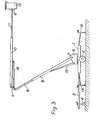
- the illustrated access equipment comprises a trailer 1, mounted upon road wheels 2 and provided with a towing extension 3 supported, when not being towed, upon a retractable wheel 4.
- a turntable 5 Pivotally mounted on the trailer 1 for full-circle rotation about a vertical axis is a turntable 5 carrying a lower boom 6, in turn pivoted at 7 to enable it to be swung towards the vertical.
- a telescopic extension 8 of the lower boom 6 carries a hinge unit 9 by means of which an upper boom 10 is linked at its lower end to the boom 6.
- the upper boom 10 is also telescopically extensible and its extension 11 carries, pivoted at 12, a personnel cage 13.
- the access unit For moving to the working site, the access unit is towed on road wheels 2. Local manoeuvring of the unit at the site may be achieved using the wheels 2 and the wheel 4 in its lowered position. Throughout the moving of the unit, the beams rp and 10 remain in the collapsed or lowered position illustrated in Fig. 1. At the site, jacks 14, which in transit are retracted at the corners of the trailer 1, are extended and lowered to provide a firm working base for .the unit.
- the cage 13 is in an inclined position during transit of the unit.
- the first operation once the working base has been established is the raising of the lower boom 6 to an elevated position as shown in Fig. 2.
- the boom 6 is fully elevated when it is at an angle of about 60 degrees to the horizontal; however other designs of unit may conveniently employ different angles, for example 50 degrees or 70 degrees to the horizontal. Elevating of the boom 6 is effected by means of a ram 15.
- a release valve (not shown in the drawings but optionally located on the turntable 5 adjacent to the pivot 7) is automatically operated to allow hydraulic fluid to flow to the other motion controls of the access unit.
- the personnel cage 13 is upright and may now be entered by the operator. From within the cage, he may initiate lifting of the upper boom 10, by means of a second ram 16, about the hinge 9. Interlocks within the controls ensure that for all movements after elevation of the boom 6, the cage 13 remains upright.
- the upper boom 10 may, by way of example, be elevated until it extends horizontally.
- the outreach may be altered by simple telescopic extending of extension 11 of the upper boom 10. Thus the outreach is changed without any tail-swing of the hinge 9.
- Vertical adjustment of the spatial position of the cage 13 may be achieved by elevation or lowering of the boom 10 or by extending or retracting the extension 8 of the lower beam 6.
- the first alternative avoids the problem of tail-swing and the second has less effect on outreach.
- the unit When the operating cycle of the unit has been completed, the unit may be "collapsed" by the reverse sequence of operations, the boom 10, the cage 13 and the extensions 8 and 11 all being returned to the position shown in Fig. 2 before the lower boom 6 is lowered to the horizontal as the final operation. Because the lower boom 6 is locked in the elevated position throughout the working cycle, it is not necessary to provide, as is conventional, elaborate control equipment to prevent the lower boom being lowered when the upper boom is elevated. Moreover, for the same reason, the rams 15 and 16 and the ram (not visible in the drawings) for extending the member 8 may all be single-acting 3 ams, since their retraction is effected by gravity.
- the illustrated embodiment of the invention is specifically designed as a towable trailer unit.
- the present invention is equally suited to mounting upon a static or other form of supporting structure or for direct mounting upon a driven chassis or upon the body of a conventional or modified vehicle.
Landscapes
- Engineering & Computer Science (AREA)
- Structural Engineering (AREA)
- Life Sciences & Earth Sciences (AREA)
- Geology (AREA)
- Mechanical Engineering (AREA)
- Forklifts And Lifting Vehicles (AREA)
- Liquid Crystal Substances (AREA)
- Lubricants (AREA)
- Electrical Discharge Machining, Electrochemical Machining, And Combined Machining (AREA)
Priority Applications (1)
| Application Number | Priority Date | Filing Date | Title |
|---|---|---|---|
| AT84306932T ATE39468T1 (de) | 1983-10-18 | 1984-10-11 | Arbeitsplattform. |
Applications Claiming Priority (2)
| Application Number | Priority Date | Filing Date | Title |
|---|---|---|---|
| GB8327848 | 1983-10-18 | ||
| GB838327848A GB8327848D0 (en) | 1983-10-18 | 1983-10-18 | Access equipment |
Publications (3)
| Publication Number | Publication Date |
|---|---|
| EP0141552A2 true EP0141552A2 (de) | 1985-05-15 |
| EP0141552A3 EP0141552A3 (en) | 1986-08-06 |
| EP0141552B1 EP0141552B1 (de) | 1988-12-28 |
Family
ID=10550378
Family Applications (1)
| Application Number | Title | Priority Date | Filing Date |
|---|---|---|---|
| EP84306932A Expired EP0141552B1 (de) | 1983-10-18 | 1984-10-11 | Arbeitsplattform |
Country Status (5)
| Country | Link |
|---|---|
| US (1) | US4643273A (de) |
| EP (1) | EP0141552B1 (de) |
| AT (1) | ATE39468T1 (de) |
| DE (1) | DE3475773D1 (de) |
| GB (1) | GB8327848D0 (de) |
Cited By (3)
| Publication number | Priority date | Publication date | Assignee | Title |
|---|---|---|---|---|
| EP0223761A1 (de) * | 1985-11-20 | 1987-05-27 | Hansen & Skov A/S | Fahrbares Hebezeug |
| EP0832841A3 (de) * | 1996-09-25 | 1999-07-14 | Grove U.S. LLC | Mobilkran |
| US6317919B1 (en) | 1998-10-23 | 2001-11-20 | William G. Dahlin | Railcar cleaning apparatus |
Families Citing this family (19)
| Publication number | Priority date | Publication date | Assignee | Title |
|---|---|---|---|---|
| US4775029A (en) | 1987-10-08 | 1988-10-04 | Jlg Industries, Inc. | Collapsible tower boom lift |
| US5427197A (en) | 1992-12-07 | 1995-06-27 | Waters; David | Pruning system |
| US5819534A (en) * | 1996-09-25 | 1998-10-13 | Simon-Telelect, Inc. | Articulated aerial device with hydraulic upper boom compensation |
| US5944204A (en) * | 1997-09-19 | 1999-08-31 | Altec Industries, Inc. | Hydraulic boom compensation system for aerial devices |
| US6390312B1 (en) | 1998-02-27 | 2002-05-21 | Jlg Industries, Inc. | Lift structures and lifting arrangement therefor |
| AU3686899A (en) * | 1998-07-01 | 2000-01-20 | Grove U.S. L.L.C. | Transportable crane |
| US6523221B1 (en) | 1998-10-23 | 2003-02-25 | William G. Dahlin | Railcar cleaning method and apparatus |
| US6889798B2 (en) * | 2000-03-08 | 2005-05-10 | Steven L. Overby | Apparatus for controlled stabilized descent |
| US6955025B2 (en) * | 2002-09-11 | 2005-10-18 | Clipper Windpower Technology, Inc. | Self-erecting tower and method for raising the tower |
| EP1896682B1 (de) * | 2005-06-16 | 2013-05-01 | Barjoh PTY Ltd. | Fahrzeugzugangssystem |
| US7234565B1 (en) | 2005-12-19 | 2007-06-26 | Thomson & Leonard | Convertible lift assembly |
| US20070137944A1 (en) * | 2005-12-19 | 2007-06-21 | Hong Lam | Vertical lift assembly |
| US20080169158A1 (en) * | 2007-01-16 | 2008-07-17 | Hong Lam | Twin Screw Scissor Lift Assembly |
| US9267342B2 (en) | 2012-06-14 | 2016-02-23 | Warrior Energy Services Corporation | Pipe handling apparatus and method |
| US8899901B2 (en) * | 2012-06-14 | 2014-12-02 | Warrior Energy Services Corporation | Pipe handling apparatus and method |
| US8950996B2 (en) | 2012-06-14 | 2015-02-10 | Warrior Energy Services Corporation | Pipe handling apparatus and method |
| US20130233646A1 (en) * | 2012-03-07 | 2013-09-12 | Carl Boysaw | Mobile and Stabilizing Scaffold Apparatus |
| CN106629523B (zh) * | 2016-10-25 | 2018-09-25 | 徐州海伦哲专用车辆股份有限公司 | 一种具有自稳定系统的高空作业车及其自稳定控制方法 |
| KR102140188B1 (ko) * | 2019-01-29 | 2020-07-31 | 전주대학교 산학협력단 | 다단식 붐대의 지지장치 |
Family Cites Families (10)
| Publication number | Priority date | Publication date | Assignee | Title |
|---|---|---|---|---|
| US2905262A (en) * | 1955-07-20 | 1959-09-22 | Daniel H Zwight | Mast control and deck leveling means for vehicle supported mast structure |
| FR1362135A (fr) * | 1963-06-10 | 1964-05-29 | Erray Eric Rayman & Co G M B H | échafaudage volant monté sur roues |
| US3461989A (en) * | 1967-11-29 | 1969-08-19 | Chance Co Ab | Mechanism for preventing excessive relative swinging of an articulated aerial device |
| CH503257A (de) * | 1968-07-19 | 1971-02-15 | Bandstahlkombinat Sitz Eisenhu | Verfahren und Vorrichtung zum kontinuierlichen Messen der Abweichungen des Durchmessers zylindrischer Körper, vorzugsweise Walzen, über die gesamte Länge |
| FR2345388A1 (fr) * | 1976-03-25 | 1977-10-21 | Sabria Const Metalliques Marce | Elevateur telescopique |
| US4081055A (en) * | 1977-01-24 | 1978-03-28 | Teco, Inc. | Hydraulic device for controlling the perpendicularity of boom members in mobile platforms |
| DE7925229U1 (de) * | 1979-09-06 | 1981-04-02 | Förster, Wolfram Lothar, 2800 Bremen | Hubarbeitsbuehne mit voneinander unabhaengiger teleskopbewegung und schwenkbewegung des auslegers |
| IT8005120A0 (it) * | 1980-02-20 | 1980-02-20 | Cella Spa | Dispositivo di limitazione di un'apparecchiatura di sollevamento con braccio ad allungamento telescopico ovvero articolato e telescopico. |
| US4411368A (en) * | 1980-03-21 | 1983-10-25 | Roger Manjot | Safety system for hydraulically controlled hoisting apparatus |
| SE423620B (sv) * | 1980-09-08 | 1982-05-17 | Kranlyft Ab | Sekerhetsanordning for hydrauliskt manovrerade manskapsliftar |
-
1983
- 1983-10-18 GB GB838327848A patent/GB8327848D0/en active Pending
-
1984
- 1984-10-11 DE DE8484306932T patent/DE3475773D1/de not_active Expired
- 1984-10-11 EP EP84306932A patent/EP0141552B1/de not_active Expired
- 1984-10-11 AT AT84306932T patent/ATE39468T1/de not_active IP Right Cessation
- 1984-10-15 US US06/661,291 patent/US4643273A/en not_active Expired - Fee Related
Cited By (4)
| Publication number | Priority date | Publication date | Assignee | Title |
|---|---|---|---|---|
| EP0223761A1 (de) * | 1985-11-20 | 1987-05-27 | Hansen & Skov A/S | Fahrbares Hebezeug |
| US4726445A (en) * | 1985-11-20 | 1988-02-23 | Hansen & Skov A/S | Mobile lift |
| EP0832841A3 (de) * | 1996-09-25 | 1999-07-14 | Grove U.S. LLC | Mobilkran |
| US6317919B1 (en) | 1998-10-23 | 2001-11-20 | William G. Dahlin | Railcar cleaning apparatus |
Also Published As
| Publication number | Publication date |
|---|---|
| ATE39468T1 (de) | 1989-01-15 |
| US4643273A (en) | 1987-02-17 |
| GB8327848D0 (en) | 1983-11-16 |
| EP0141552A3 (en) | 1986-08-06 |
| EP0141552B1 (de) | 1988-12-28 |
| DE3475773D1 (en) | 1989-02-02 |
Similar Documents
| Publication | Publication Date | Title |
|---|---|---|
| EP0141552B1 (de) | Arbeitsplattform | |
| AU601564B2 (en) | Collapsible tower boom lift | |
| US4070807A (en) | Aerial lift | |
| US5014863A (en) | Vehicle mounted crane | |
| US3845596A (en) | Drive system for a telescopic boom | |
| US5005714A (en) | Crane, in particular a large mobile crane | |
| US2375264A (en) | Vehicle stabilizing arrangement | |
| US5704498A (en) | Transportable crane | |
| US3834488A (en) | Aerial platform with articulating jib | |
| US4498596A (en) | Supplementary equipment for use with a self-propelled crane with a telescopic jib | |
| US5117595A (en) | Device for erecting and aligning a tilting telescopic mast mounted on a transport vehicle | |
| EP0978472A2 (de) | Fahrbarer Kran | |
| RU2260558C2 (ru) | Самоходная тележка с телескопической стрелой и увеличителем высоты | |
| US2595897A (en) | Tractor mounted crane | |
| US4770271A (en) | Transportable, articulated-arm crane | |
| JPS594600A (ja) | 接近用プラツトフオ−ム | |
| CA1317555C (en) | Mobile lifting apparatus with articulating and telescoping links for a manually levellable nacelle | |
| JP3392244B2 (ja) | 高所作業車 | |
| JP3392262B2 (ja) | 高所作業車 | |
| JPH0411476B2 (de) | ||
| JPH0718711Y2 (ja) | 作業車のブーム受け | |
| JPH021359Y2 (de) | ||
| JPS606073Y2 (ja) | クレ−ン車 | |
| WO2025261929A1 (en) | Telescopic handler | |
| MXPA99006220A (en) | Transportation crane |
Legal Events
| Date | Code | Title | Description |
|---|---|---|---|
| PUAI | Public reference made under article 153(3) epc to a published international application that has entered the european phase |
Free format text: ORIGINAL CODE: 0009012 |
|
| AK | Designated contracting states |
Designated state(s): AT BE CH DE FR GB IT LI NL SE |
|
| PUAL | Search report despatched |
Free format text: ORIGINAL CODE: 0009013 |
|
| AK | Designated contracting states |
Kind code of ref document: A3 Designated state(s): AT BE CH DE FR GB IT LI NL SE |
|
| 17P | Request for examination filed |
Effective date: 19870202 |
|
| 17Q | First examination report despatched |
Effective date: 19871022 |
|
| GRAA | (expected) grant |
Free format text: ORIGINAL CODE: 0009210 |
|
| AK | Designated contracting states |
Kind code of ref document: B1 Designated state(s): AT BE CH DE FR GB IT LI NL SE |
|
| PG25 | Lapsed in a contracting state [announced via postgrant information from national office to epo] |
Ref country code: NL Effective date: 19881228 Ref country code: LI Effective date: 19881228 Ref country code: IT Free format text: LAPSE BECAUSE OF FAILURE TO SUBMIT A TRANSLATION OF THE DESCRIPTION OR TO PAY THE FEE WITHIN THE PRESCRIBED TIME-LIMIT;WARNING: LAPSES OF ITALIAN PATENTS WITH EFFECTIVE DATE BEFORE 2007 MAY HAVE OCCURRED AT ANY TIME BEFORE 2007. THE CORRECT EFFECTIVE DATE MAY BE DIFFERENT FROM THE ONE RECORDED. Effective date: 19881228 Ref country code: CH Effective date: 19881228 Ref country code: BE Effective date: 19881228 Ref country code: AT Effective date: 19881228 |
|
| REF | Corresponds to: |
Ref document number: 39468 Country of ref document: AT Date of ref document: 19890115 Kind code of ref document: T |
|
| REF | Corresponds to: |
Ref document number: 3475773 Country of ref document: DE Date of ref document: 19890202 |
|
| REG | Reference to a national code |
Ref country code: CH Ref legal event code: PL |
|
| ET | Fr: translation filed | ||
| NLV1 | Nl: lapsed or annulled due to failure to fulfill the requirements of art. 29p and 29m of the patents act | ||
| PGFP | Annual fee paid to national office [announced via postgrant information from national office to epo] |
Ref country code: FR Payment date: 19891025 Year of fee payment: 6 |
|
| PGFP | Annual fee paid to national office [announced via postgrant information from national office to epo] |
Ref country code: SE Payment date: 19891027 Year of fee payment: 6 |
|
| ITTA | It: last paid annual fee | ||
| PGFP | Annual fee paid to national office [announced via postgrant information from national office to epo] |
Ref country code: GB Payment date: 19891031 Year of fee payment: 6 |
|
| PLBE | No opposition filed within time limit |
Free format text: ORIGINAL CODE: 0009261 |
|
| STAA | Information on the status of an ep patent application or granted ep patent |
Free format text: STATUS: NO OPPOSITION FILED WITHIN TIME LIMIT |
|
| PGFP | Annual fee paid to national office [announced via postgrant information from national office to epo] |
Ref country code: DE Payment date: 19891130 Year of fee payment: 6 |
|
| 26N | No opposition filed | ||
| PG25 | Lapsed in a contracting state [announced via postgrant information from national office to epo] |
Ref country code: GB Effective date: 19901011 |
|
| PG25 | Lapsed in a contracting state [announced via postgrant information from national office to epo] |
Ref country code: SE Effective date: 19901012 |
|
| GBPC | Gb: european patent ceased through non-payment of renewal fee | ||
| PG25 | Lapsed in a contracting state [announced via postgrant information from national office to epo] |
Ref country code: FR Effective date: 19910628 |
|
| PG25 | Lapsed in a contracting state [announced via postgrant information from national office to epo] |
Ref country code: DE Effective date: 19910702 |
|
| REG | Reference to a national code |
Ref country code: FR Ref legal event code: ST |
|
| EUG | Se: european patent has lapsed |
Ref document number: 84306932.9 Effective date: 19910603 |