EP0141572B1 - Maschine zum Verpacken einer geniessbaren Flüssigkeit - Google Patents
Maschine zum Verpacken einer geniessbaren Flüssigkeit Download PDFInfo
- Publication number
- EP0141572B1 EP0141572B1 EP84307078A EP84307078A EP0141572B1 EP 0141572 B1 EP0141572 B1 EP 0141572B1 EP 84307078 A EP84307078 A EP 84307078A EP 84307078 A EP84307078 A EP 84307078A EP 0141572 B1 EP0141572 B1 EP 0141572B1
- Authority
- EP
- European Patent Office
- Prior art keywords
- containers
- conveyor
- wheel
- ribbon
- cover stock
- Prior art date
- Legal status (The legal status is an assumption and is not a legal conclusion. Google has not performed a legal analysis and makes no representation as to the accuracy of the status listed.)
- Expired
Links
- 239000007788 liquid Substances 0.000 title claims abstract description 13
- 238000004806 packaging method and process Methods 0.000 title abstract description 9
- 238000007789 sealing Methods 0.000 claims abstract description 30
- 230000001954 sterilising effect Effects 0.000 claims description 14
- 238000001035 drying Methods 0.000 claims description 9
- MHAJPDPJQMAIIY-UHFFFAOYSA-N Hydrogen peroxide Chemical compound OO MHAJPDPJQMAIIY-UHFFFAOYSA-N 0.000 claims description 8
- 238000001816 cooling Methods 0.000 claims description 6
- 238000004659 sterilization and disinfection Methods 0.000 claims description 5
- 239000000853 adhesive Substances 0.000 claims description 4
- 230000001070 adhesive effect Effects 0.000 claims description 4
- 239000000126 substance Substances 0.000 claims description 4
- XLYOFNOQVPJJNP-UHFFFAOYSA-N water Substances O XLYOFNOQVPJJNP-UHFFFAOYSA-N 0.000 claims description 3
- 238000012856 packing Methods 0.000 claims 1
- 230000003252 repetitive effect Effects 0.000 claims 1
- 238000005507 spraying Methods 0.000 claims 1
- 239000003566 sealing material Substances 0.000 description 4
- 239000000945 filler Substances 0.000 description 2
- 239000004033 plastic Substances 0.000 description 2
- 229920003023 plastic Polymers 0.000 description 2
- XAGFODPZIPBFFR-UHFFFAOYSA-N aluminium Chemical compound [Al] XAGFODPZIPBFFR-UHFFFAOYSA-N 0.000 description 1
- 229910052782 aluminium Inorganic materials 0.000 description 1
- 239000004411 aluminium Substances 0.000 description 1
- 230000001276 controlling effect Effects 0.000 description 1
- 239000002826 coolant Substances 0.000 description 1
- 239000006071 cream Substances 0.000 description 1
- 230000000694 effects Effects 0.000 description 1
- 238000010438 heat treatment Methods 0.000 description 1
- 229920001903 high density polyethylene Polymers 0.000 description 1
- 239000004700 high-density polyethylene Substances 0.000 description 1
- 230000036512 infertility Effects 0.000 description 1
- 239000000463 material Substances 0.000 description 1
- 238000000034 method Methods 0.000 description 1
- 239000008267 milk Substances 0.000 description 1
- 210000004080 milk Anatomy 0.000 description 1
- 235000013336 milk Nutrition 0.000 description 1
- 230000002028 premature Effects 0.000 description 1
- 238000012414 sterilization procedure Methods 0.000 description 1
- 230000032258 transport Effects 0.000 description 1
Images


Classifications
-
- B—PERFORMING OPERATIONS; TRANSPORTING
- B65—CONVEYING; PACKING; STORING; HANDLING THIN OR FILAMENTARY MATERIAL
- B65B—MACHINES, APPARATUS OR DEVICES FOR, OR METHODS OF, PACKAGING ARTICLES OR MATERIALS; UNPACKING
- B65B55/00—Preserving, protecting or purifying packages or package contents in association with packaging
- B65B55/02—Sterilising, e.g. of complete packages
- B65B55/04—Sterilising wrappers or receptacles prior to, or during, packaging
- B65B55/10—Sterilising wrappers or receptacles prior to, or during, packaging by liquids or gases
-
- B—PERFORMING OPERATIONS; TRANSPORTING
- B65—CONVEYING; PACKING; STORING; HANDLING THIN OR FILAMENTARY MATERIAL
- B65B—MACHINES, APPARATUS OR DEVICES FOR, OR METHODS OF, PACKAGING ARTICLES OR MATERIALS; UNPACKING
- B65B43/00—Forming, feeding, opening or setting-up containers or receptacles in association with packaging
- B65B43/42—Feeding or positioning bags, boxes, or cartons in the distended, opened, or set-up state; Feeding preformed rigid containers, e.g. tins, capsules, glass tubes, glasses, to the packaging position; Locating containers or receptacles at the filling position; Supporting containers or receptacles during the filling operation
- B65B43/52—Feeding or positioning bags, boxes, or cartons in the distended, opened, or set-up state; Feeding preformed rigid containers, e.g. tins, capsules, glass tubes, glasses, to the packaging position; Locating containers or receptacles at the filling position; Supporting containers or receptacles during the filling operation using roller-ways or endless conveyors
-
- B—PERFORMING OPERATIONS; TRANSPORTING
- B65—CONVEYING; PACKING; STORING; HANDLING THIN OR FILAMENTARY MATERIAL
- B65B—MACHINES, APPARATUS OR DEVICES FOR, OR METHODS OF, PACKAGING ARTICLES OR MATERIALS; UNPACKING
- B65B51/00—Devices for, or methods of, sealing or securing package folds or closures; Devices for gathering or twisting wrappers, or necks of bags
- B65B51/32—Cooling, or cooling and pressing, package closures after heat-sealing
-
- B—PERFORMING OPERATIONS; TRANSPORTING
- B65—CONVEYING; PACKING; STORING; HANDLING THIN OR FILAMENTARY MATERIAL
- B65B—MACHINES, APPARATUS OR DEVICES FOR, OR METHODS OF, PACKAGING ARTICLES OR MATERIALS; UNPACKING
- B65B55/00—Preserving, protecting or purifying packages or package contents in association with packaging
- B65B55/02—Sterilising, e.g. of complete packages
- B65B55/04—Sterilising wrappers or receptacles prior to, or during, packaging
- B65B55/08—Sterilising wrappers or receptacles prior to, or during, packaging by irradiation
-
- B—PERFORMING OPERATIONS; TRANSPORTING
- B65—CONVEYING; PACKING; STORING; HANDLING THIN OR FILAMENTARY MATERIAL
- B65B—MACHINES, APPARATUS OR DEVICES FOR, OR METHODS OF, PACKAGING ARTICLES OR MATERIALS; UNPACKING
- B65B7/00—Closing containers or receptacles after filling
- B65B7/16—Closing semi-rigid or rigid containers or receptacles not deformed by, or not taking-up shape of, contents, e.g. boxes or cartons
- B65B7/28—Closing semi-rigid or rigid containers or receptacles not deformed by, or not taking-up shape of, contents, e.g. boxes or cartons by applying separate preformed closures, e.g. lids, covers
- B65B7/2807—Feeding closures
- B65B7/2814—Feeding closures the closures being interconnected
Definitions
- the present invention relates to an apparatus for packaging an edible liquid in individual sterilized containers.
- the apparatus particularly relates to the packaging of small quantities, i.e. 10 ml of milk or cream in sterile plastic containers for use in restaurants or the like, but the apparatus may also be used for packaging quantities of liquids up to about 200 ml.
- Prior devices utilize a conveyor for moving containers at one level from station to station for the purpose of effecting the various steps comprising the packaging of liquids.
- a conveyor for moving containers at one level from station to station for the purpose of effecting the various steps comprising the packaging of liquids.
- FR-A-2401 065 there is disclosed an apparatus with such a conveyor on which filled containers on a straight run of the conveyor are sealed with a ribbon of sealing material which is subsequently severed between the sealed containers.
- Such severing is likewise effected whilst the filled containers are on a straight run of the conveyor.
- movement of the filled containers on a straight run of the conveyor between sealing and severing can lead to tension in the ribbon of sealing material between the sealed containers sufficient undesirably to break the sealing material prematurely possibly in positions leading to break down of the seal of the adjacent container.
- Such strip tension can also lead to misalignment between sealing material and containers still to be sealed with subsequent mis-sealing.
- the present apparatus utilizes the lower level of an endless conveyor to effect sterilization of the containers prior to the filling and sealing steps which take place on the upper level of the conveyor.
- This container sterilization step is carried out by introducing the containers onto the conveyor in an inverted position so that the interiors thereof can be chemically sterilized, drained and dried readily immediately prior to filling.
- the present apparatus also provides an improved heat sealing station for applying a ribbon of cover stock to the filled containers.
- This improved sealing means comprises the use of a payout wheel to feed cover stock over an idler roller and into a heated sealing wheel. This arrangement ensures an even heating of the cover stock and a precise registration of the cover stock being applied to the containers, thereby providing a reliable liquid seal.
- an apparatus for packaging an edible liquid in sterile, sealed containers having rims about the openings thereof including an endless conveyor having upper and lower levels by which at least one row of containers are conveyed through the apparatus; means for feeding containers onto the conveyor which is provided with parallel rails for supporting the containers by the rims thereof; means for chemically sterilizing the containers as they move along the lower level of the conveyor; means for filling the sterile containers with the liquid as they move along the upper level of the conveyor; means for sealing the filled containers about the rims thereof, comprising a ribbon of sterile cover stock for application to the containers; and a cutter located after sealing means for severing the connecting ribbon of cover stock between containers, characterised in that the means for feeding containers on to the conveyor is operable such that it feeds inverted containers onto the lower level of the conveyor, the ribbon of sterile cover stock has a heat sensitive adhesive thereon and is fed over a payout wheel on to a heated sealing wheel, the cutter is a cut off wheel, and a slightly upwardly
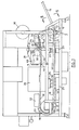
- the inverted cups 10 are captured by a conveyor 18 which comprises a plurality of collars 19 attached to parallel chains 20 (Fig. 2) driven by a sprocket wheel 21.
- the cups 10 are conveyed along a pair of parallel rails 22 to a chemical sterilization station 23 where the cups 10 are sprayed with a suitable sterilizing solution such as 35% hydrogen peroxide.
- the inverted cups 10 drain as they are conveyed to a drying station 25 where heated air is forced over the interior and exterior surfaces of the cups thereby drying them.
- the sterile cups 10 are conveyed on the rails 22 around the end of the conveyor 18 to the upper level of the conveyor 18 where they are filled with the desired edible liquid at a filling station 28 and then capped by a heat sealing wheel 30 with a ribbon of sterile cover stock 31 fed in register onto each cup by a sealing means 35.
- the cover stock 31 sealed onto the cups 10 is severed by a cutoff wheel 37 and the now filled and sealed cups 10 are conveyed from the apparatus by an ejector wheel 40.
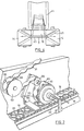
- FIGS 3, 4 and 5 illustrate details of the cup feeding mechanism.
- the inverted cups 10 are stacked in a chute 11 from which they are removed one at a time by a pair of escapement wheels 14.
- the wheels 14 engage the lip or rim 43 of each cup 10 in the spiral groove 45 provided in each wheel 14.
- the groove 45 causes each cup 10 to travel from the chute 11 onto a tooth 1 of the feeder wheel 13 in a sequential fashion.
- the feeder wheel 13 immediately transports each cup 10 onto a pair of parallel rails 22 where the cups 10 are supported by their rims 43 and are sequentially captured by the collars 19 of the conveyor 18 which then assumes the control over the movement of the cups 10 to the various stations of the apparatus.
- the speed of movement of the wheel 13 is matched to the speed of the conveyor 18 so that each tooth 12 of the wheel 13 can sequentially deliver a cup 10 to each successive collar 1 : 9 of the conveyor 18.
- the rotation of the escapement wheels 14 is adjusted to the rotational speed of the wheel 13 so that one cup 10 is deposited on each successive tooth 12 of the wheel 13 which passes therebetween.
- the preferred embodiment comprises several rows of cups 10, preferably the commercial apparatus has four rows.
- adjacent rows of cups 10 preferably use an escapement wheel 14 commonly.
- a shaft 46 is provided with gears 47 for rotating adjacent escapement wheels 14 in opposite directions. This means that the cups 10 in adjacent rows descent into their respective feeder wheels 13 at different times.
- the cup 10 in the adjacent row is only one half way down onto a tooth 12 of its feeder wheel 13. This means that the conveyors 18 of adjacent rows must be adjusted accordingly as shown in Figures 6 and 7.
- the inverted cups 10 are conveyed along the rails 22, which are preferably made of a plastic material, by the conveyor 18 to the chemical sterilizing station 23 and then to the drying station 25. Because the cups 10 are inverted, the sterilization procedure may be carried out more quickly than is the case with other devices since the solution used to sterilize the cups 10 quickly drains from the interiors thereof, and the cups 10 may be quickly dried upon a short exposure to the heated air of the drying station 25. At the drying station 25 air at a temperature of approximately 100°C is forced through a series of nozzles 50 onto all surfaces of the cups 10 as they pass through.
- the cups are conveyed along the rails 22 around the end of the conveyor 18 to the upper level of the conveyor 18 where the cups 10 are situated upright in the collars 19 which engage and support the cups 10 at the underside of the rims 43 thereof.
- the cups 10 may be held from contacting the rails 22 by means of sterile air forced through a series of nozzles 70. The cups 10 may then pass beneath an ultraviolet light 52 before moving on to the filling station 28.
- the liquid filling station 28 may be of any suitable design familiar to those experienced in this art.
- the cups 10 are filled at the station 28 by means of a multiple nozzle filler which travels along with several cups 10 until then desired volume has been introduced into each cup 10 at which time the filler moves back to the next group of cups and repeats the process.
- a five nozzle fillter is preferred.
- the filled cups 10 are conveyed to the sealing station 35 ( Figures 1 and 2) where a ribbon of sterile cover stock 31 is applied by the heated wheel 30.
- the cover stock is provided with a heat sensitive adhesive.
- the conveyor 18 proceeds along parallel arms 55 which comprise a ramp for raising the cups 10 into good contact with the surface of the wheel 30 upon application of the cover stock 31 thereto.
- the arms 55 may be made of a high density polyethylene having a low coefficient of friction with respect to the conveyor 18.
- the arms 55 are raised or lowered about pivots 56 by air cylinders (not shown). Generally, the angle of the ramp 55 above horizontal is only of the order of 1°.
- the cover stock 31 is fed as a ribbon from a spool 60 through a chemical sterilization bath 61 which preferably contains a constant flow of 35% hydrogen peroxide. From the bath 61, the cover stock 31 travels over a payout wheel 63 which is equipped with indexing buttons 65 corresponding to the spacing or pitch of the individual covers.
- the buttons 65 serve to accurately feed the cover stock 31 over an idler wheel 66 onto the larger heat sealing wheel 30 which is also equipped with indexing buttons 65 so that the individual covers are applied in register with the rims 43 of the cups 10 passing beneath the wheel 30. It has been found that without the controlling effect of the payout wheel 63 and the indexing buttons 65, the cover stock 31 cannot reliably be applied to the individual cups 10 with the tolerance needed for a high speed capping operation as in the present case.
- the cups 10 proceed preferably along an upwardly concavely curved ramp comprising arms 67 which engage the collars 19 in the same manner as the arms 55 (see Figures 8 and 9).
- the arms 67 serve to tilt the collars 19 slightly toward one another in a gentle arc so that tension on the ribbon of cover stock 31 sealed to the cups 10 is relieved prior to the severing operation.
- a cooling shoe 68 which just contacts the sealed ribbon of cover stock 31 immediately after the heated sealing wheel 30 for the purpose of fixing the adhesive forming the seal about the rims 43 of the cups 10.
- the cooling shoe 68 has lower surface 69 curved to conform to the curvature of the arms 67.
- the cooling shoe 68 may conveniently be made of aluminium and is hollow to allow for a flow of coolant such as water therethrough.
- the cups 10 proceed along the curved arms 67 to a cutoff wheel 37 where the ribbon of cover 31 is severed between the cups 10.
- the cutoff wheel 37 is of conventional design and has its own drive 70.
- the wheel 37 may be raised and lowered when setting up the machine by means of an air cylinder 71.
- the arms 67 may continue past the cutoff wheel 37 but do not need to be curved after the ribbon 31 is severed.
- the individual sealed cups 10 are conveyed from the cutoff wheel 37 over an ejectment wheel 40 where they are ejected from the collars 19 of the conveyor 18 into a collecting chute for further packaging steps.
Landscapes
- Engineering & Computer Science (AREA)
- Mechanical Engineering (AREA)
- Health & Medical Sciences (AREA)
- General Health & Medical Sciences (AREA)
- Toxicology (AREA)
- Microelectronics & Electronic Packaging (AREA)
- Apparatus For Disinfection Or Sterilisation (AREA)
- Formation And Processing Of Food Products (AREA)
- Vacuum Packaging (AREA)
- Closing Of Containers (AREA)
Claims (19)
Priority Applications (1)
| Application Number | Priority Date | Filing Date | Title |
|---|---|---|---|
| AT84307078T ATE32324T1 (de) | 1983-10-17 | 1984-10-16 | Maschine zum verpacken einer geniessbaren fluessigkeit. |
Applications Claiming Priority (2)
| Application Number | Priority Date | Filing Date | Title |
|---|---|---|---|
| CA000439155A CA1209547A (en) | 1983-10-17 | 1983-10-17 | Apparatus for packaging an edible liquid |
| CA439155 | 1983-10-17 |
Publications (3)
| Publication Number | Publication Date |
|---|---|
| EP0141572A2 EP0141572A2 (de) | 1985-05-15 |
| EP0141572A3 EP0141572A3 (en) | 1985-06-12 |
| EP0141572B1 true EP0141572B1 (de) | 1988-02-03 |
Family
ID=4126301
Family Applications (1)
| Application Number | Title | Priority Date | Filing Date |
|---|---|---|---|
| EP84307078A Expired EP0141572B1 (de) | 1983-10-17 | 1984-10-16 | Maschine zum Verpacken einer geniessbaren Flüssigkeit |
Country Status (6)
| Country | Link |
|---|---|
| US (1) | US4563855A (de) |
| EP (1) | EP0141572B1 (de) |
| JP (1) | JPS60148411A (de) |
| AT (1) | ATE32324T1 (de) |
| CA (1) | CA1209547A (de) |
| DE (1) | DE3469155D1 (de) |
Families Citing this family (13)
| Publication number | Priority date | Publication date | Assignee | Title |
|---|---|---|---|---|
| US4817363A (en) * | 1987-09-02 | 1989-04-04 | Owens-Illinois Plastic Products Inc. | Fitment inserter machine |
| US5058726A (en) * | 1989-12-15 | 1991-10-22 | Fmc Corporation | Tray feed arrangement |
| US5251423A (en) * | 1990-05-30 | 1993-10-12 | Gasti Verpackungsmachinen Gmbh | Method of and apparatus for sterile packaging using stacked packaging elements, especially plastic cups with varying wall thickness |
| FR2682082B1 (fr) * | 1991-10-04 | 1995-04-07 | Metalliques Floren Const | Procede de groupage de pots dans une clayette et machine pour la mise en óoeuvre du procede. |
| DE4313325C2 (de) * | 1993-04-23 | 2000-01-13 | Tetra Pak Gmbh | Vorrichtung zum Füllen und Verschließen von Packungen |
| US5857309A (en) * | 1997-03-28 | 1999-01-12 | Tetra Laval Holdings & Finance, S.A. | Apparatus for sterilizing a spout assembly of a container |
| US6073422A (en) * | 1998-08-11 | 2000-06-13 | Osceola Foods, Inc. | Filling and lidding machine and method |
| WO2003037720A2 (en) * | 2001-10-30 | 2003-05-08 | International Product Technology, Inc. | Method and apparatus for sealing cover tape to carrier tape |
| EP1992560A3 (de) * | 2004-04-20 | 2008-11-26 | Jörgen Henriksen | Band aus Behälterverschlüssen |
| ITMI20091108A1 (it) * | 2009-06-23 | 2010-12-24 | Cottino Francesco | Metodo e apparecchiatura per la sterilizzazione di calzature |
| EP3347277B1 (de) * | 2015-09-11 | 2021-02-17 | Primoreels A/S | Vorrichtung zum weiterleiten von verschlussrohlingen von einer bahn |
| ES2967918T3 (es) * | 2019-04-19 | 2024-05-06 | Siropack Italia S R L | Método para fabricar un contenedor para productos alimenticios |
| CN111846457A (zh) * | 2020-07-15 | 2020-10-30 | 湖南津山口福食品有限公司 | 一种腌制食品用包装消毒装置 |
Family Cites Families (12)
| Publication number | Priority date | Publication date | Assignee | Title |
|---|---|---|---|---|
| FR2120765A5 (en) * | 1970-12-28 | 1972-08-18 | Hamba Maschinen H Muller | Packaging liquid foods - automatically and sterilising containers |
| DE2214080C3 (de) * | 1972-03-23 | 1975-11-13 | Hamba-Maschinenfabrik Hans A. Mueller, 5600 Wuppertal-Vohwinkel | Vorrichtung zum sterilen Abfüllen von Nahrungs- und Genußmitteln |
| US3775934A (en) * | 1972-04-06 | 1973-12-04 | Purity Packaging Ltd | Method of and apparatus for applying caps to containers |
| US3783581A (en) * | 1972-04-18 | 1974-01-08 | Dart Ind Inc | Aseptic packaging method and machine |
| US4042148A (en) * | 1974-05-16 | 1977-08-16 | Solo Cup Company | Cup filling and capping apparatus |
| CH615131A5 (de) * | 1974-12-11 | 1980-01-15 | Aluminiumwerke Ag Rorschach | |
| US4077180A (en) * | 1976-06-17 | 1978-03-07 | Portion Packaging, Inc. | Method and apparatus for packaging fluent material |
| US4152464A (en) * | 1977-08-22 | 1979-05-01 | The Mead Corporation | Method for the aseptic packaging of high acid food |
| US4409775A (en) * | 1977-08-22 | 1983-10-18 | The Mead Corporation | Apparatus for the aseptic packing of high acid food |
| JPS5444988A (en) * | 1977-09-16 | 1979-04-09 | Dainippon Printing Co Ltd | Sterile packaging machine |
| US4296068A (en) * | 1979-02-19 | 1981-10-20 | Dai Nippon Insatsu Kabushiki Kaisha | Apparatus for sterilizing a succession of food containers or the like |
| CA1161741A (en) * | 1981-05-11 | 1984-02-07 | Consumers Glass Company Limited | Ultraviolet sterilization system |
-
1983
- 1983-10-17 CA CA000439155A patent/CA1209547A/en not_active Expired
-
1984
- 1984-02-21 US US06/581,534 patent/US4563855A/en not_active Expired - Lifetime
- 1984-10-16 AT AT84307078T patent/ATE32324T1/de not_active IP Right Cessation
- 1984-10-16 DE DE8484307078T patent/DE3469155D1/de not_active Expired
- 1984-10-16 EP EP84307078A patent/EP0141572B1/de not_active Expired
- 1984-10-17 JP JP59216450A patent/JPS60148411A/ja active Pending
Also Published As
| Publication number | Publication date |
|---|---|
| EP0141572A2 (de) | 1985-05-15 |
| ATE32324T1 (de) | 1988-02-15 |
| JPS60148411A (ja) | 1985-08-05 |
| EP0141572A3 (en) | 1985-06-12 |
| US4563855A (en) | 1986-01-14 |
| DE3469155D1 (en) | 1988-03-10 |
| CA1209547A (en) | 1986-08-12 |
Similar Documents
| Publication | Publication Date | Title |
|---|---|---|
| US4563855A (en) | Apparatus for packaging an edible liquid | |
| US4409775A (en) | Apparatus for the aseptic packing of high acid food | |
| US3783581A (en) | Aseptic packaging method and machine | |
| US4803055A (en) | Apparatus for sterilizing containers | |
| US3939625A (en) | Device for printing and feeding covers to containers | |
| US4077180A (en) | Method and apparatus for packaging fluent material | |
| US4441955A (en) | Base cup applicator | |
| US3800400A (en) | Automatic plastic bottling system and method | |
| CA2059440C (en) | Container filling system and sealing system | |
| US3112590A (en) | Packaging system and apparatus | |
| US3279927A (en) | Packer | |
| US2962846A (en) | Cap assembling and applying apparatus | |
| US4274532A (en) | Can handling system | |
| US5158168A (en) | Container transfer device | |
| EP3202677A1 (de) | Behälterfördervorrichtung | |
| US3744212A (en) | Automatic plastic bottling system and method | |
| US5335474A (en) | Apparatus for supplying containers to a sealing device | |
| JPH072229A (ja) | 液体容器搬送処理装置 | |
| US3376689A (en) | Packaging apparatus and method of utilizing the same | |
| JPH05508139A (ja) | 液体用パック容器の充填及び封口加工装置 | |
| US4505089A (en) | Carrier applicator | |
| US3935967A (en) | Apparatus for feeding shell-like articles | |
| JP4579862B2 (ja) | 容器用のラベリング機械 | |
| JPS62295822A (ja) | 包装機から容器を取り出すための搬送装置 | |
| JPH0466414A (ja) | 容器処理装置 |
Legal Events
| Date | Code | Title | Description |
|---|---|---|---|
| PUAI | Public reference made under article 153(3) epc to a published international application that has entered the european phase |
Free format text: ORIGINAL CODE: 0009012 |
|
| PUAL | Search report despatched |
Free format text: ORIGINAL CODE: 0009013 |
|
| AK | Designated contracting states |
Designated state(s): AT BE CH DE FR GB IT LI LU NL SE |
|
| AK | Designated contracting states |
Designated state(s): AT BE CH DE FR GB IT LI LU NL SE |
|
| 17P | Request for examination filed |
Effective date: 19851128 |
|
| 17Q | First examination report despatched |
Effective date: 19860716 |
|
| GRAA | (expected) grant |
Free format text: ORIGINAL CODE: 0009210 |
|
| AK | Designated contracting states |
Kind code of ref document: B1 Designated state(s): AT BE CH DE FR GB IT LI LU NL SE |
|
| PG25 | Lapsed in a contracting state [announced via postgrant information from national office to epo] |
Ref country code: NL Effective date: 19880203 Ref country code: LI Effective date: 19880203 Ref country code: IT Free format text: LAPSE BECAUSE OF FAILURE TO SUBMIT A TRANSLATION OF THE DESCRIPTION OR TO PAY THE FEE WITHIN THE PRESCRIBED TIME-LIMIT;WARNING: LAPSES OF ITALIAN PATENTS WITH EFFECTIVE DATE BEFORE 2007 MAY HAVE OCCURRED AT ANY TIME BEFORE 2007. THE CORRECT EFFECTIVE DATE MAY BE DIFFERENT FROM THE ONE RECORDED. Effective date: 19880203 Ref country code: FR Free format text: THE PATENT HAS BEEN ANNULLED BY A DECISION OF A NATIONAL AUTHORITY Effective date: 19880203 Ref country code: CH Effective date: 19880203 Ref country code: BE Effective date: 19880203 Ref country code: AT Effective date: 19880203 |
|
| REF | Corresponds to: |
Ref document number: 32324 Country of ref document: AT Date of ref document: 19880215 Kind code of ref document: T |
|
| PG25 | Lapsed in a contracting state [announced via postgrant information from national office to epo] |
Ref country code: SE Effective date: 19880229 |
|
| REF | Corresponds to: |
Ref document number: 3469155 Country of ref document: DE Date of ref document: 19880310 |
|
| REG | Reference to a national code |
Ref country code: CH Ref legal event code: PL |
|
| EN | Fr: translation not filed | ||
| NLV1 | Nl: lapsed or annulled due to failure to fulfill the requirements of art. 29p and 29m of the patents act | ||
| PG25 | Lapsed in a contracting state [announced via postgrant information from national office to epo] |
Ref country code: LU Free format text: LAPSE BECAUSE OF NON-PAYMENT OF DUE FEES Effective date: 19881031 |
|
| PLBE | No opposition filed within time limit |
Free format text: ORIGINAL CODE: 0009261 |
|
| STAA | Information on the status of an ep patent application or granted ep patent |
Free format text: STATUS: NO OPPOSITION FILED WITHIN TIME LIMIT |
|
| 26N | No opposition filed | ||
| PG25 | Lapsed in a contracting state [announced via postgrant information from national office to epo] |
Ref country code: DE Effective date: 19890701 |
|
| REG | Reference to a national code |
Ref country code: GB Ref legal event code: IF02 |
|
| PGFP | Annual fee paid to national office [announced via postgrant information from national office to epo] |
Ref country code: GB Payment date: 20031103 Year of fee payment: 20 |
|
| PG25 | Lapsed in a contracting state [announced via postgrant information from national office to epo] |
Ref country code: GB Free format text: LAPSE BECAUSE OF EXPIRATION OF PROTECTION Effective date: 20041015 |
|
| REG | Reference to a national code |
Ref country code: GB Ref legal event code: PE20 |