EP0141577A2 - Verfahren und Einrichtung zur Herstellung eines kontinuierlichen Bandes - Google Patents
Verfahren und Einrichtung zur Herstellung eines kontinuierlichen Bandes Download PDFInfo
- Publication number
- EP0141577A2 EP0141577A2 EP84307108A EP84307108A EP0141577A2 EP 0141577 A2 EP0141577 A2 EP 0141577A2 EP 84307108 A EP84307108 A EP 84307108A EP 84307108 A EP84307108 A EP 84307108A EP 0141577 A2 EP0141577 A2 EP 0141577A2
- Authority
- EP
- European Patent Office
- Prior art keywords
- die
- chill surface
- strip
- molten
- space
- Prior art date
- Legal status (The legal status is an assumption and is not a legal conclusion. Google has not performed a legal analysis and makes no representation as to the accuracy of the status listed.)
- Withdrawn
Links
- 238000000034 method Methods 0.000 title claims description 22
- 239000000463 material Substances 0.000 claims abstract description 30
- 238000005266 casting Methods 0.000 claims abstract description 14
- 239000012768 molten material Substances 0.000 claims description 38
- 238000007493 shaping process Methods 0.000 claims description 7
- 239000010935 stainless steel Substances 0.000 claims description 3
- 229910001220 stainless steel Inorganic materials 0.000 claims description 3
- 229910000881 Cu alloy Inorganic materials 0.000 claims description 2
- 239000011819 refractory material Substances 0.000 claims description 2
- 239000007787 solid Substances 0.000 abstract 1
- ATJFFYVFTNAWJD-UHFFFAOYSA-N Tin Chemical compound [Sn] ATJFFYVFTNAWJD-UHFFFAOYSA-N 0.000 description 14
- 229910052718 tin Inorganic materials 0.000 description 14
- 229910045601 alloy Inorganic materials 0.000 description 13
- 239000000956 alloy Substances 0.000 description 13
- 229910052751 metal Inorganic materials 0.000 description 12
- 239000002184 metal Substances 0.000 description 12
- 238000001816 cooling Methods 0.000 description 11
- 230000000694 effects Effects 0.000 description 10
- 239000010949 copper Substances 0.000 description 9
- 229910052802 copper Inorganic materials 0.000 description 6
- 239000004411 aluminium Substances 0.000 description 5
- XAGFODPZIPBFFR-UHFFFAOYSA-N aluminium Chemical compound [Al] XAGFODPZIPBFFR-UHFFFAOYSA-N 0.000 description 5
- 239000007789 gas Substances 0.000 description 5
- 229910000838 Al alloy Inorganic materials 0.000 description 4
- IJGRMHOSHXDMSA-UHFFFAOYSA-N Atomic nitrogen Chemical compound N#N IJGRMHOSHXDMSA-UHFFFAOYSA-N 0.000 description 4
- 229910052782 aluminium Inorganic materials 0.000 description 4
- 229910052710 silicon Inorganic materials 0.000 description 4
- RYGMFSIKBFXOCR-UHFFFAOYSA-N Copper Chemical compound [Cu] RYGMFSIKBFXOCR-UHFFFAOYSA-N 0.000 description 3
- 229910000831 Steel Inorganic materials 0.000 description 3
- 239000001996 bearing alloy Substances 0.000 description 3
- 230000015572 biosynthetic process Effects 0.000 description 3
- 230000005499 meniscus Effects 0.000 description 3
- 239000010703 silicon Substances 0.000 description 3
- 238000007711 solidification Methods 0.000 description 3
- 230000008023 solidification Effects 0.000 description 3
- 239000010959 steel Substances 0.000 description 3
- PXHVJJICTQNCMI-UHFFFAOYSA-N Nickel Chemical compound [Ni] PXHVJJICTQNCMI-UHFFFAOYSA-N 0.000 description 2
- 229910052581 Si3N4 Inorganic materials 0.000 description 2
- 229910001128 Sn alloy Inorganic materials 0.000 description 2
- MCMNRKCIXSYSNV-UHFFFAOYSA-N Zirconium dioxide Chemical compound O=[Zr]=O MCMNRKCIXSYSNV-UHFFFAOYSA-N 0.000 description 2
- 238000009749 continuous casting Methods 0.000 description 2
- 230000007423 decrease Effects 0.000 description 2
- 239000006185 dispersion Substances 0.000 description 2
- 239000011261 inert gas Substances 0.000 description 2
- 239000010410 layer Substances 0.000 description 2
- 238000004519 manufacturing process Methods 0.000 description 2
- 229910001092 metal group alloy Inorganic materials 0.000 description 2
- 229910052757 nitrogen Inorganic materials 0.000 description 2
- 239000002245 particle Substances 0.000 description 2
- HQVNEWCFYHHQES-UHFFFAOYSA-N silicon nitride Chemical compound N12[Si]34N5[Si]62N3[Si]51N64 HQVNEWCFYHHQES-UHFFFAOYSA-N 0.000 description 2
- 239000006104 solid solution Substances 0.000 description 2
- 238000003756 stirring Methods 0.000 description 2
- VYZAMTAEIAYCRO-UHFFFAOYSA-N Chromium Chemical compound [Cr] VYZAMTAEIAYCRO-UHFFFAOYSA-N 0.000 description 1
- 229910000676 Si alloy Inorganic materials 0.000 description 1
- 229910001361 White metal Inorganic materials 0.000 description 1
- HCHKCACWOHOZIP-UHFFFAOYSA-N Zinc Chemical compound [Zn] HCHKCACWOHOZIP-UHFFFAOYSA-N 0.000 description 1
- 230000005540 biological transmission Effects 0.000 description 1
- 238000007664 blowing Methods 0.000 description 1
- 229910052793 cadmium Inorganic materials 0.000 description 1
- BDOSMKKIYDKNTQ-UHFFFAOYSA-N cadmium atom Chemical compound [Cd] BDOSMKKIYDKNTQ-UHFFFAOYSA-N 0.000 description 1
- 229910052804 chromium Inorganic materials 0.000 description 1
- 239000011651 chromium Substances 0.000 description 1
- 230000001419 dependent effect Effects 0.000 description 1
- 238000009826 distribution Methods 0.000 description 1
- 230000008014 freezing Effects 0.000 description 1
- 238000007710 freezing Methods 0.000 description 1
- 230000005484 gravity Effects 0.000 description 1
- 238000010438 heat treatment Methods 0.000 description 1
- 239000001307 helium Substances 0.000 description 1
- 229910052734 helium Inorganic materials 0.000 description 1
- SWQJXJOGLNCZEY-UHFFFAOYSA-N helium atom Chemical compound [He] SWQJXJOGLNCZEY-UHFFFAOYSA-N 0.000 description 1
- 239000006193 liquid solution Substances 0.000 description 1
- 239000000155 melt Substances 0.000 description 1
- 238000002074 melt spinning Methods 0.000 description 1
- 230000008018 melting Effects 0.000 description 1
- 238000002844 melting Methods 0.000 description 1
- 239000000203 mixture Substances 0.000 description 1
- 229910052759 nickel Inorganic materials 0.000 description 1
- 230000002093 peripheral effect Effects 0.000 description 1
- 238000005096 rolling process Methods 0.000 description 1
- 238000000926 separation method Methods 0.000 description 1
- 239000002344 surface layer Substances 0.000 description 1
- 239000010409 thin film Substances 0.000 description 1
- 239000010969 white metal Substances 0.000 description 1
- 229910052725 zinc Inorganic materials 0.000 description 1
- 239000011701 zinc Substances 0.000 description 1
Images


Classifications
-
- B—PERFORMING OPERATIONS; TRANSPORTING
- B22—CASTING; POWDER METALLURGY
- B22D—CASTING OF METALS; CASTING OF OTHER SUBSTANCES BY THE SAME PROCESSES OR DEVICES
- B22D11/00—Continuous casting of metals, i.e. casting in indefinite lengths
- B22D11/06—Continuous casting of metals, i.e. casting in indefinite lengths into moulds with travelling walls, e.g. with rolls, plates, belts, caterpillars
-
- B—PERFORMING OPERATIONS; TRANSPORTING
- B22—CASTING; POWDER METALLURGY
- B22D—CASTING OF METALS; CASTING OF OTHER SUBSTANCES BY THE SAME PROCESSES OR DEVICES
- B22D11/00—Continuous casting of metals, i.e. casting in indefinite lengths
- B22D11/06—Continuous casting of metals, i.e. casting in indefinite lengths into moulds with travelling walls, e.g. with rolls, plates, belts, caterpillars
- B22D11/0637—Accessories therefor
- B22D11/064—Accessories therefor for supplying molten metal
- B22D11/0642—Nozzles
Definitions
- the present invention relates to the continuous formation of a strip material, in particular a metal alloy strip for use as a bearing material, however, the invention may be applicable to other materials for other uses.
- Melt Spinning a stream of molten metal is directed against a rapidly moving chill surface, such as a wheel or belt, where it is:cooled instantaneously.
- This is generally used for the manufacture of thin films, for example of about 10 5 m in thickness, and frequently suffers from the disadvantage that it can be very difficult to obtain an even stream distribution.
- molten metal is made to form a meniscus of molten metal between the outlet of a nozzle-and the surface of a cooled drum or belt. As the drum surface is rotated with an upward component past the meniscus, molten metal is dragged up and away from the meniscus and cools on the drum surface to form a strip.
- a method of continuously casting a strip of material in which a shaping die is brought into contact with a relatively moving chill surface to define a space and an outlet opening between the die and the chill surface, the material in molten form is applied to the die under pressure and is brought into contact with the chill surface within the space, the said pressure, the temperature of the chill surface and the speed of relative movement between the chill surface and the die are arranged so that as the strip issues from the outlet opening its surface has solidified, and in which the strip is then removed from the chill surface.
- the outlet opening effectively acts as a continuous casting die and its contours precisely define the cross-section of the strip. It is important that the various parameters, particularly the pressure, are arranged as defined above so that freezing occurs just prior to or at the outlet opening since, for example, if the pressure is too low, the molten material may freeze in the die, while if the pressure is too high, the material may leave the outlet opening while still molten, thus losing the die effect of the outlet opening.
- the combination of the pressure and the die effect of the outlet opening helps to ensure that no gas is entrained in the strip material, with the consequent absence of voids, and also tends to improve the surface correspondence between the formed strip and the chill surface.
- the pressure also tends to improve heat transfer to the chill surface, thus increasing the cooling rate of the strip.
- apparatus for continuously casting a strip of material comprising a shaping die and a relatively movable chill surace, the die being arranged to direct the material in molten form on to the chill surface within space defined between the die and the chill surface, the die and the chill surface together defining an outlet opening through which the strip issues.
- the outlet opening is preferably a uniform slot though it may be non-uniform, for example to compensate for edge effects or centre effects.
- the slot may be deeper at the edges than it is in the centre, either by having a centre depression or by having "bulbous" edges.
- the pressure may be brought about by the head of molten material above the die or may be exerted by external means, such as gas pressure above the molten material.
- the molten material may be held in a crucible or an equivalent vessel above the die. and may be maintained in the molten state by external heating means with optional stirring, for example radio frequency stirring.
- the space is preferably defined by a rear wall and two side walls formed on the' die which closely contact the chill surface to leave-the outlet opening opposite the rear wall..
- the space preferably.- converges towards the outlet opening from the rear wall. Then is then a hydrodynamic effect as the molten metal is forced into the narrowing gap, which in turn forces the solidifying strip on to the chill surface, thus expelling any entrained gas and helping to cause the chill surface to draw out the solidified strip.
- the pressure should be arranged so that it does not exceed the value of 4 ⁇ /d, where ⁇ is the surface tension of the molten material and d is the contact clearance between the die and the chill surface.
- the molten material is delivered to the space via an inclined slot so that the change in direction of the molten material in the die is optimised. Too steep a slot may result in turbulence in the molten material while too shallow a slot may affect the transmission of the pressure. Thus, an inclination of between 45° and 80°, e.g. 70° to the direction of strip formation is preferred.
- the bore of the slot maybe about 1.5mn.
- the chill surface may comprise a belt or, more preferably, a cylindrical drum.and the relative movement between the chill surface and the - die is preferably effected by moving the chill surface, for example by rotating the drum or by driving the belt.
- the speed of relative movement may be between 0.1 and 1Q O m/s, preferably between 0.75 and 2 . 0 m/s e.g.l.5 m/s.
- the chill surface preferably has a high surface finish, for example ⁇ 10 -6 or thereabouts and is preferably highly conductive.
- the surface composition may be a copper alloy or stainless steel.
- the die is preferably made from a non-metallic refractory material, for example zirconia or silicon nitride which is both heat and wear resistant.
- the apparatus may be surrounded by an inert atmosphere e.g. nitrogen. This may be achieved by enclosing at least a part of the apparatus in an inert atmosphere, or by blowing an inert gas over the die region.
- an inert atmosphere e.g. nitrogen.
- means is preferably provided to remove any layer of air adhering to the drum surface. Such means might take the form of a suction device or a wiper or scraper for the drum sur.face.
- the present invention is particularly applicable . to the manufacture of metal bearing alloys, for example alloys of aluminium with tin, copper and optionally silicon or nickel, particularly, Al with 20% Sn and 1 % Cu and Al with 11% Si and 1% Cu.
- metal bearing alloys for example alloys of aluminium with tin, copper and optionally silicon or nickel, particularly, Al with 20% Sn and 1 % Cu and Al with 11% Si and 1% Cu.
- Previous methods of obtaining these alloys in strip form have generally necessitated casting billets of the alloys and then rolling these down. It is common to cast the material at a thickness of over 15mm and then to roll this.down to about lmm in three passes in order to obtain the desired microstructure. This is, of course, very wasteful in terms of manpower, equipment and energy, particularly since it is necessary with many alloys to head/anneal the material between the roll passes.
- the strip may be formed to the required thickness directly.
- This thickness may be between 0.5 and 2.5mm, or perhaps 0.75 to 1.5mm for example about l.Omm.
- the microstructure of the alloy tends to be extremely fine (particularly at the face contacting the chill surface) so that the material may exhibit an improved ductility.
- the alloys tend to be more workable and in fact, alloys which have hitherto been considered too brittle may now be used in bearing applications where roll bonding to a backing is called for. Certain alloys of aluminium and silicon may fall into this category, particularly Al with 10.6% Si and 1% Cu.
- aluminium/ tin For aluminium/ tin, it has been found that 80% of the alloy solidifies by the time the temperature has reached 500°C, though . a temperature of about 200°C is required to allow convenient handling. With aluminium/silicon/tin, or alloys sold under the Trade Mark Lo-eX, these are handleable at about 575°C, while copper/lead can only be handled at about 300°C. Since the strip tends to come off a drum at perhaps about 480° in the case of a 0.5m diameter drum, the strip may be supported on an air cushioning system since this involves no physical handling and also cools the strip.
- One of the problems with Al/Sn as a bearing material is the difficulty in forming a direct bond with a steel backing. This is due to the presence of regions of. pure tin at the surface.
- the rapid cooling employed in the method of the present invention results in a microcrystalline surface layer of the bearing material where it contacts the chill surface.
- the cooling is so rapid that a non-equilibrium or metastable microstructure is formed in which the tin is present as an atomic dispersion or solid solution, i.e. it is frozen in the form in which it was when in liquid solution before the tin atoms have had time to agglomerate.
- the alloy is in this form there is no tendency for the tin to affect the bond to a steel backing.
- agglomerated tin particles in the alloy.
- the proportion of agglomerated tin increases, though of course the actual proportion of tin itself is generally constant throughout the strip.
- a strip may be produced which has one surface whose properties enable it to be bonded directly to a steel backing and another surface which has the desired bearing properties.
- a method of continuously casting a strip of material in which a shaping die is brought into contact with a relatively movable chill surface to define a space and an outlet opening between the die and the chill surface, the material in molten form is applied to the die and is brought into contact with the chill surface within the space, a negative pressure is applied to the molten material, and in which, when the relative movement between the die and the chill surface is at the desired speed, a positive pressure is applied to the molten metal at the chill surface.
- the negative pressure is achieved effectively by "sucking" at the molten material while the positive pressure is achieved by applying an inert gas, e.g. nitrogen, to the molten material.
- an inert gas e.g. nitrogen
- hpg is greater than ; where h is the head of molten material; p is the density of the molten material; g is the force exerted by gravity; ⁇ is the surface tension of the molten material, and 0 is the bore of the slot leading to the space, then dribbling will occur. In order to ensure that no dribbling occurs, a negative pressure is applied thereby effectively reducing the effect of the term hpg.
- the negative pressure applied is not sufficiently great to suck gas bubbles back through the molten material.
- the negative pressure should not exceed hpg + 4Y .
- the positive pressure P applied to the molten material should be greater than .
- an applied pressure of 2 to 15 psi (70 to 1050 kg/m 2 ), preferably 3 to 8 psi (210 to 560 kg/m 2 ), for example 5 psi (350 kg/m 2 ) is generally sufficient.
- the negative pressure is a function of ⁇ p and the positive pressure is controlled in_ dependance upon the drum speed, the die dimensions and the density and surface tension of the molten material. This control is preferably achieved by an automatic control system which may also make pressure adjustments during a casting run.
- a stopper rod may be used. This stopper rod would be movable from a closed position in which the molten metal is prevented from contacting the chill surface and an open position in which the molten metal is allowed to flow through the die when the required parameters have been achieved.
- the invention may also be applied to the formation of multi-layer strips.
- the strips may be formed sequentially from the molten state by methods in accordance with the invention.
- the strip After the strip has been produced and removed from the chill surface, it can either be directed to a coiling or take up device or may be fed directly to roll bonding apparatus for bonding to a backing.
- the shaping die is in the form of a nozzle 11 which has a generally cylindrical body 12 composed of silicon nitride.
- the upper part of the body 12 is generally . hollow and has a bayonnet fitting 13 for attaching the nozzle 11 to a suitable crucible (not shown) for a molten bearing alloy.
- the underside of the nozzle 11 has a flat portion 14 and an upwardly curved concave portion 15 whose curvature follows that of a cylindrical stainless steel drum 16 as shown in Figure 5.
- a channel 17 is formed in the curved portion 15 having a rear wall 18 and two side walls 19, 21.
- the channel defines with the drum a space 22 which gradually converges towards an outlet opening 23 between the nozzle 11 and the drum 16.
- the outlet opening 23 is in the form of a rectangular slot, the cylindrical surface of the drum 16 having been cut away as shown at 24.
- the space 22 is connected to the hollow interior of the nozzle 11 by an inclined slot 25.
- the slot 25 may be of constant cross-section or may converge downwards as shown in Figure 5 or as shown by the chain line 26 in Figure 1.
- the gauge of the slot 25 is 1.5mm.
- the nozzle 11 is located on the surface of the drum 16, as shown in Figure 5, with the bases of the rear wall 18 and two side walls 19, 21 in close contact with the drum surface leaving a contact clearance d.
- Molten material is then fed under pressure to the nozzle 11 and travels down the slot 25 to the space 22, thus coming into contact with the surface of the drum 16, which is rotated with a peripheral speed of about 1.5m/s in the direction of arrow B.
- the molten material solidifies by transferring heat to the drum 16, the solidification front being totally within the space 22 and being indicated generally by the chain line 27 in Figure 5.
- the pressure on the molten material and the rotation of the drum draws the solidified strip out of the outlet opening 23 as shown in broken lines 28.
- the solidified strip remains in contact with the drum for a short distance after leaving the nozzle and is then removed. Since the strip has solidified before leaving the space 22, the contour of the outlet opening 23 defines precisely the cross-sectional shape of the strip.
- the convergent shape of the space 22 enhances the hydrodynamic effect of the molten material which exerts pressure on the forming strip which in turn tends to expel any bubbles from the material of the strip while also inproving the surface finish-
- the top surface 29 of the space 22 is shown as being horizontal and planar, it could be inclined and or somewhat curved to follow to an extent the curvature of the drum 16.
- the maximum cooling rate is at the drum surface and decreases through the thickness of the strip.
- the material at the lower surface tends to he a solid solution, with the t i n present as an atomic dispersion, while the material at the upper.surface includes agglomerated tin atoms giving rise to tin particles..
- the drum 16 may be cooled and the nozzle 11 may be heated or cooled near the outlet opening 23.
- the pressure on the molten material must also be taken into consideration to ensure that it is sufficient to prevent the molten material solidifying so rapidly that a blockage occurs, but that its value is below 4/d, where ⁇ is the surface tension of the molten material and d is the contact clearance, so that the molten material is not squeezed out past the rear and side walls 18, 19 and 21.
- drum rotation rate molten material temperature
- drum surface temperature and pressure depending on the nature of the molten material and the thickness of the strip.
- Means may be incorporated to vary the thickness of the strip, the angle of the channel 22 leading to the outlet opening etc..
- Figures 6 to 8 show alternative forms for the slot connecting the channel 17 to the interior of the nozzle 11.
- the nozzles are shown upside down and have been simplified for clarity by omitting the interior detail of the nozzles and the cutaway portion 24.
- the slots are shown as being vertical as opposed to inclined and this is indeed a possible alternative. 'In fact, the slots could also be vertical and generally convergent towards the channel 17.
- the slot 25 and therefore the rear wall 18, are angled. This may help to increase the flow of material for a given strip thickness.
- the slot 25, and therefore the rear wall 18 are curved, so as to be concave from the direction of the channel 17. This may help to compensate for uneven cooling due to edge effects.
- the slot 25 and the rear wall 18 are set at an oblique angle to the side walls 19, 21. This may help to increase the flow rate of molten material, which may be required in the case of a thicker strip.
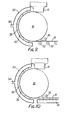
- Figure 9 shows a second embodiment in which the solidified strip 31 is maintained in contact with the drum 16 rather than removing it almost immediately as shown in Figure 5.
- the strip is in contact with the drum through about 180° and is then run out on rollers 32, though a belt or a run-out table may be used in place of the rollers 32.
- This arrangement has the advantage that the strip 31 is in contact with the drum 16 for a considerably greater length of time, thus enabling more heat to be transferred to the drum 16 with the result that the strip 31 is much cooler and probably easier to handle as it runs out.
- a shroud 33 surrounds that portion of the drum 16 which the strip 16 contacts.
- the shroud 33 has a compressed air inlet 34 supplying air at about 80 psi and a series of outlets of slits 35 directed towards the strip 31 on the drum 16.
- the air pressure on the strip 31 also helps to improve the heat transfer to the drum 16.
- the rollers 32 are replaced by an air cushioning system 41 on which the strip 31 is supported.
- This arrangement is particularly suitable in the case of high melting point alloys, such as Cu/Pb which comes off the drum at about 480 C. Under these conditions, the strip 31 is rather difficult to handle directly, and the air cushion additionally helps to cool the strip further.
- shroud 33 is shown as being spaced from the strip surface, it can equally well be arranged to provide an effectively sealed channel for the air along the lines of the "hovercraft principle" in order to minimise the amount of air used. Furthermore, although high pressure air is used in this embodiment, it might be preferable to use helium, which although more costly, has a better cooling effect.
- a high pressure air knife 36 is located at the take-off point. This delivers air at about 80 psi.
- rollers 32 ray be replaced by an air cushioning support system. This has the advantage of cooling the strip without physical contact.
- the nozzle 11 is shown as being generally circular, it could of course be any appropriate shape e.g. sqaure or rectangular when viewed from above.
- the invention has been described as being suitable for aluminium based bearing alloys, it is also suitable for tin and lead based white metals, for example Sn/Cu/Sb optionally with additional chromium and cadmium and Pb/Sb/Sn and also for copper based alloys such as Cu with lead and/or tin, optionally with zinc.
- tin and lead based white metals for example Sn/Cu/Sb optionally with additional chromium and cadmium and Pb/Sb/Sn
- copper based alloys such as Cu with lead and/or tin, optionally with zinc.
Landscapes
- Engineering & Computer Science (AREA)
- Mechanical Engineering (AREA)
- Continuous Casting (AREA)
Applications Claiming Priority (4)
| Application Number | Priority Date | Filing Date | Title |
|---|---|---|---|
| GB838327830A GB8327830D0 (en) | 1983-10-18 | 1983-10-18 | Continuous strip |
| GB8327830 | 1983-10-18 | ||
| GB8403328 | 1984-02-08 | ||
| GB848403328A GB8403328D0 (en) | 1984-02-08 | 1984-02-08 | Forming continuous strip |
Publications (2)
| Publication Number | Publication Date |
|---|---|
| EP0141577A2 true EP0141577A2 (de) | 1985-05-15 |
| EP0141577A3 EP0141577A3 (de) | 1985-06-12 |
Family
ID=26286924
Family Applications (1)
| Application Number | Title | Priority Date | Filing Date |
|---|---|---|---|
| EP84307108A Withdrawn EP0141577A3 (de) | 1983-10-18 | 1984-10-17 | Verfahren und Einrichtung zur Herstellung eines kontinuierlichen Bandes |
Country Status (4)
| Country | Link |
|---|---|
| EP (1) | EP0141577A3 (de) |
| KR (1) | KR850004029A (de) |
| AU (1) | AU3354484A (de) |
| GB (1) | GB2148764A (de) |
Cited By (1)
| Publication number | Priority date | Publication date | Assignee | Title |
|---|---|---|---|---|
| WO1987005545A1 (en) * | 1986-03-20 | 1987-09-24 | Battelle Development Corporation | Wire casting |
Families Citing this family (4)
| Publication number | Priority date | Publication date | Assignee | Title |
|---|---|---|---|---|
| DE3423834A1 (de) * | 1984-06-28 | 1986-01-09 | Mannesmann AG, 4000 Düsseldorf | Verfahren und vorrichtung zum kontinuierlichen giessen von metallschmelze, insbesondere von stahlschmelze |
| GB2182876A (en) * | 1985-11-14 | 1987-05-28 | Atomic Energy Authority Uk | Alloy strip production |
| US5053286A (en) * | 1986-01-23 | 1991-10-01 | Federal-Mogul Corporation | Aluminum-lead engine bearing alloy metallurgical structure and method of making same |
| GB2225740B (en) * | 1988-11-19 | 1993-05-19 | Glyco Metall Werke | A method and a device for the manufacture of laminar material for slide elements |
Family Cites Families (9)
| Publication number | Priority date | Publication date | Assignee | Title |
|---|---|---|---|---|
| GB711866A (en) * | 1951-06-21 | 1954-07-14 | Clevite Ltd | Continuous casting apparatus for aluminium or other molten metals onto metallic strip metal |
| GB728300A (en) * | 1951-10-30 | 1955-04-20 | Joseph Barry Brennan | Improvements in or relating to the continuous casting of metal |
| GB735869A (en) * | 1952-03-03 | 1955-08-31 | Joseph Barry Brennan | Improvements in and relating to the continuous casting of molted metal materials |
| GB736401A (en) * | 1952-03-17 | 1955-09-07 | Brennan Joseph Barry | Improvements in or relating to the continuous casting of materials |
| GB729555A (en) * | 1952-03-17 | 1955-05-11 | Joseph Barry Brennan | Method of and apparatus for casting and bonding metal upon and to a strip |
| US2770022A (en) * | 1952-12-08 | 1956-11-13 | Joseph B Brennan | Method of continuously casting molten metal |
| DE2132757A1 (de) * | 1970-07-06 | 1972-01-20 | Canada Metal Co Ltd | Maschine zum kontinuierlichen Giessen eines bandfoermigen Gitters |
| US4212343A (en) * | 1979-03-16 | 1980-07-15 | Allied Chemical Corporation | Continuous casting method and apparatus for structurally defined metallic strips |
| DE3136303A1 (de) * | 1981-09-12 | 1983-04-14 | Vacuumschmelze Gmbh, 6450 Hanau | Vorrichtung fuer die herstellung von metallband aus einer schmelze |
-
1984
- 1984-09-26 AU AU33544/84A patent/AU3354484A/en not_active Abandoned
- 1984-10-12 KR KR1019840006308A patent/KR850004029A/ko not_active Abandoned
- 1984-10-17 EP EP84307108A patent/EP0141577A3/de not_active Withdrawn
- 1984-10-17 GB GB08426202A patent/GB2148764A/en not_active Withdrawn
Cited By (1)
| Publication number | Priority date | Publication date | Assignee | Title |
|---|---|---|---|---|
| WO1987005545A1 (en) * | 1986-03-20 | 1987-09-24 | Battelle Development Corporation | Wire casting |
Also Published As
| Publication number | Publication date |
|---|---|
| EP0141577A3 (de) | 1985-06-12 |
| GB8426202D0 (en) | 1984-11-21 |
| KR850004029A (ko) | 1985-07-01 |
| AU3354484A (en) | 1985-04-26 |
| GB2148764A (en) | 1985-06-05 |
Similar Documents
| Publication | Publication Date | Title |
|---|---|---|
| CA1078111A (en) | Continuous casting method for metallic strips | |
| US4221257A (en) | Continuous casting method for metallic amorphous strips | |
| CA1180875A (en) | Method and apparatus for strip casting | |
| US4751957A (en) | Method of and apparatus for continuous casting of metal strip | |
| US3432293A (en) | Bearing materials and method of making same | |
| JPS61253149A (ja) | 金属薄板の連続鋳造による製造装置 | |
| GB2148764A (en) | Method and apparatus for casting a continuous strip | |
| CA1296505C (en) | Continuous casting of thin metal strip | |
| US4285386A (en) | Continuous casting method and apparatus for making defined shapes of thin sheet | |
| US5293926A (en) | Method and apparatus for direct casting of continuous metal strip | |
| US4331739A (en) | Amorphous metallic strips | |
| EP0526886A1 (de) | Gussen eines Metallbandes | |
| EP0040073B1 (de) | Vorrichtung zum Giessen eines Streifens | |
| US5063989A (en) | Method and apparatus for planar drag strip casting | |
| JPH0255642A (ja) | ストリツプ鋼を連続的に鋳造する方法および装置 | |
| EP0448773A2 (de) | Stranggussform und Stranggussverfahren | |
| WO1987002285A1 (en) | Method of and apparatus for continuous casting of metal strip | |
| EP0463223A2 (de) | Verfahren und Einrichtung zum Bandstranggiessen | |
| EP0387271B1 (de) | Verfahren und vorrichtung zum direkten giessen von metall zur bildung langer körper | |
| EP0233283B1 (de) | Verfahren zum stranggiessen eines metallbandes auf einem tragband | |
| US3903954A (en) | Apparatus for pouring molten metal | |
| GB2103972A (en) | Process for high-speed vertical continuous casting of aluminium and alloys thereof | |
| US4763718A (en) | Method of and apparatus for casting an elongated metal product | |
| US5143146A (en) | Casting of metal strip | |
| EP0040069B1 (de) | Vorrichtung zum Giessen eines Streifens |
Legal Events
| Date | Code | Title | Description |
|---|---|---|---|
| PUAI | Public reference made under article 153(3) epc to a published international application that has entered the european phase |
Free format text: ORIGINAL CODE: 0009012 |
|
| PUAL | Search report despatched |
Free format text: ORIGINAL CODE: 0009013 |
|
| AK | Designated contracting states |
Designated state(s): AT BE CH DE FR GB IT LI LU NL SE |
|
| AK | Designated contracting states |
Designated state(s): AT BE CH DE FR GB IT LI LU NL SE |
|
| STAA | Information on the status of an ep patent application or granted ep patent |
Free format text: STATUS: THE APPLICATION IS DEEMED TO BE WITHDRAWN |
|
| 18D | Application deemed to be withdrawn |
Effective date: 19860213 |
|
| RIN1 | Information on inventor provided before grant (corrected) |
Inventor name: JOLLY, MARK |