EP0141679B1 - Système optique pour un dispositif de mémoire magnéto-optique - Google Patents
Système optique pour un dispositif de mémoire magnéto-optique Download PDFInfo
- Publication number
- EP0141679B1 EP0141679B1 EP84307685A EP84307685A EP0141679B1 EP 0141679 B1 EP0141679 B1 EP 0141679B1 EP 84307685 A EP84307685 A EP 84307685A EP 84307685 A EP84307685 A EP 84307685A EP 0141679 B1 EP0141679 B1 EP 0141679B1
- Authority
- EP
- European Patent Office
- Prior art keywords
- beam splitter
- optical
- optical system
- polarization
- polarization beam
- Prior art date
- Legal status (The legal status is an assumption and is not a legal conclusion. Google has not performed a legal analysis and makes no representation as to the accuracy of the status listed.)
- Expired
Links
- 230000003287 optical effect Effects 0.000 title claims description 53
- 230000010287 polarization Effects 0.000 claims description 59
- 230000010363 phase shift Effects 0.000 claims description 12
- 239000010409 thin film Substances 0.000 claims description 9
- 230000005540 biological transmission Effects 0.000 claims 1
- 230000006870 function Effects 0.000 description 8
- 238000001514 detection method Methods 0.000 description 7
- 238000010586 diagram Methods 0.000 description 6
- 230000008033 biological extinction Effects 0.000 description 3
- 230000006866 deterioration Effects 0.000 description 3
- 239000004065 semiconductor Substances 0.000 description 3
- 230000000694 effects Effects 0.000 description 2
- 239000010408 film Substances 0.000 description 2
- 229910045601 alloy Inorganic materials 0.000 description 1
- 239000000956 alloy Substances 0.000 description 1
- 229910000808 amorphous metal alloy Inorganic materials 0.000 description 1
- 238000006073 displacement reaction Methods 0.000 description 1
- 239000000696 magnetic material Substances 0.000 description 1
- 238000000034 method Methods 0.000 description 1
- 230000007935 neutral effect Effects 0.000 description 1
- 229910052761 rare earth metal Inorganic materials 0.000 description 1
- 150000002910 rare earth metals Chemical class 0.000 description 1
- 229910052723 transition metal Inorganic materials 0.000 description 1
- 150000003624 transition metals Chemical class 0.000 description 1
Images

Classifications
-
- G—PHYSICS
- G11—INFORMATION STORAGE
- G11B—INFORMATION STORAGE BASED ON RELATIVE MOVEMENT BETWEEN RECORD CARRIER AND TRANSDUCER
- G11B11/00—Recording on or reproducing from the same record carrier wherein for these two operations the methods are covered by different main groups of groups G11B3/00 - G11B7/00 or by different subgroups of group G11B9/00; Record carriers therefor
- G11B11/10—Recording on or reproducing from the same record carrier wherein for these two operations the methods are covered by different main groups of groups G11B3/00 - G11B7/00 or by different subgroups of group G11B9/00; Record carriers therefor using recording by magnetic means or other means for magnetisation or demagnetisation of a record carrier, e.g. light induced spin magnetisation; Demagnetisation by thermal or stress means in the presence or not of an orienting magnetic field
- G11B11/105—Recording on or reproducing from the same record carrier wherein for these two operations the methods are covered by different main groups of groups G11B3/00 - G11B7/00 or by different subgroups of group G11B9/00; Record carriers therefor using recording by magnetic means or other means for magnetisation or demagnetisation of a record carrier, e.g. light induced spin magnetisation; Demagnetisation by thermal or stress means in the presence or not of an orienting magnetic field using a beam of light or a magnetic field for recording by change of magnetisation and a beam of light for reproducing, i.e. magneto-optical, e.g. light-induced thermomagnetic recording, spin magnetisation recording, Kerr or Faraday effect reproducing
- G11B11/10532—Heads
Definitions
- the present invention relates to a magneto-optical memory device, wherein information is recorded into, read out from, or erased from a recording medium by applying a laser beam onto the recording medium having a magnetic thin-film recording layer.
- the present invention relates, more particularly, to an optical system in a magneto-optical memory device.
- an optical memory system which ensures a high density storage, a large capacity storage, and-a high speed accessing.
- an optical memory system wherein a row of fine pits are formed in a recording medium and the diffraction effect of the light beam at the pit portions is used for reproduction purposes, or another optical memory system wherein bit shaped areas having a different refractive index are formed in a recording medium and the variation of the refractive index or the transparency is used for reproduction purposes are on the way of the practical application.
- the optical memory system can only perform the reproduction operation, or can perform the add-on recording at best. That is, the conventional optical memory system cannot perform the erase operation which must be one of the most remarkable features of the memory system.
- a magneto-optical memory system which includes a recording medium made of magnetic material.
- the magneto-optical memory system is very effective because the recording/erasing operation is easily conducted in the magneto-optical memory system.
- the conventional magneto-optical memory system can not ensure the high quality of the reproduced signal, and the optical system thereof is complicated.
- EP-0078673 describes an optical system for a magneto-optical memory device which includes a recording medium in the form of a magnetic thin-film having a magnetic anisotropy in a plane perpendicular to the main surface thereof, and a laser for reproduction purposes, said optical system comprising: a polarisation beam splitter disposed in an optical path of said optical system and a multi-layered dielectric thin-film deposited on a reflection surface of said beam splitter.
- a deterioration in the signal-to-noise ratio arises from a phase shift being introduced between the P-wave and the S-wave which are reflected or transmitted from the beam splitter.
- phase shift is discussed in an article by Mansuripur, Connell and Goodman entitled “Signal and Noise in Magneto-Optical Readout” appearing in the Journal of Applied Physics, Vol. 53 (June 1982), No. 6, New York, U.S.A.
- phase plate is incorporated in the optical system.
- a magnetic recording medium 1 includes an amorphous alloy thin-film recording layer, having a magnetic anisotropy in a direction perpendicular to the major surface thereof, made of the alloy of rare earth metal and transition metal.
- An embodiment of an optical system of a magneto-optical memory device of the present invention includes a semiconductor laser 2 emitting the laser beam at a predetermined intensity.
- the laser beam emitted from the semiconductor laser 2 is converted into a parallel beam by a collimator lens 3, and is introduced into a prism 4 which functions to convert the ellipse laser beam into the approximately circular laser beam.
- the beam introducing surface of the prism 4 is coated with a film which minimizes the reflection of the P-polarized beam.
- a polarization beam splitter 5 is disposed in the optical system so as to apply the reproduced beam reflected from the recording medium 1 to a detection system.
- the polarization beam splitter 5 functions to improve the polarization of the transmitting beam, and to further rotate the polarization direction of the relecting beam, thereby increasing the apparent magneto-optic rotation angle. Functions of the polarization beam splitter 5 will be described later in detail.
- a total reflection prism 6 is disposed in the optical system so as to change the optical path by 90°.
- the slant face of the total reflection prism 6 is coated with a multi-layered dielectric film which maintains the phase shift between the S-wave and the P-wave at nn. That is, the total reflection prism 6 changes the optical path by 90° without changing the polarized condition of the introduced beam.
- An objective lens 7 functions to provide a fine spot on the recording medium 1.
- Another polarization beam splitter 8 is provided so as to introduce the reproduced beam from the polarization beam splitter 5.
- the polarization beam splitter 8 also functions to increase the magneto-optic rotation angle of the reflecting beam.
- the reproduced beam reflected at the polarization beam splitter 8 is introduced into a spot lens 9 via a half-wave plate 10.
- the spot lens 9 functions to apply the reproduced beam to a detection system at a desired beam size.
- the half-wave plate 10 functions to rotate the polarization direction of the reproduced beam in a desired direction.
- a polarization beam splitter 11 separates the S-polarization and the P-polarization.
- the detected, reproduced beam is applied to light responsive elements 12 and 13, respectively.
- Each of the light responsive elements 12 and 13 is preferably made of a Si PIN photodiode, or a Si APD (Avalanche Photo Doide).
- the optical system further includes a spot lens 14, and a cylindrical lens 15.
- the cylindrical lens 15 has the focal line which is inclined by 45° with respect to the tangent direction of the track formed on the recording medium 1.
- a complex detection unit 16 is provided so as to detect the variation of the relative distance between the recording medium 1 and the objective lens 7 through the use of the synergism effects of the spot lens 14 and the cylindrical lens 15. The complex detection unit 16 further detects the displacement of the beam spot from the information track, namely the tracking informetion.
- the polarization beam splitters 5 and 8 have the relection r, against the P-polarization, and the relection r s against the S-polarization.
- the reflection rp should be small so as to ensure the desirable increase of the magneto-optic rotation angle.
- the increase of the magneto-optic rotation angle produced by the polarization beam splitter of the type I, 11 and III is, at its increasing ratio, about 2.1, about 1.8 and about 1.6, respectively.
- Desired polarization beam splitters 5 and 8 should be selected with reference to the transmitting light intensity and the reflecting light intensity.
- the polarization beam splitter 5 should have a high transmissivity in order to reduce the laser power in the writing operation. However, the transmissivity of the polarization beam splitter 5 should not be extremely high because the reproduced signal should be transferred to the detection unit via the polarization beam splitter 5.
- the (r P ) 2 of the polarization beam splitter 5 should be selected between 0.1 and 0.5.
- the (rp) 2 of the polarization beam splitter 8 is preferably between 0.05 and 0.5 when the light responsive elements 12 and 13 are made of Avalanche Photo Diode (APD). This is because the reproduced signal has a high quality when the signal modulation factor is high.
- APD Avalanche Photo Diode
- Figure 2 is a vector diagram showing the optical characteristics of the polarization beam splitters 5 and 8.
- the optical system is arranged in a manner that the laser beam emitted from the semiconductor laser 2 is the P-polarization beam with respect to the polarization beam splitter 5.
- the laser beam reaching the recording medium 1 maintains the polarized condition, and has the energy of (1-(rP)2) times.
- the laser beam reflected at the recording medium 1 and introduced again into the polarization beam splitter 5 has the plane of polarization which is slightly rotated in the clockwise direction or in the counter-clockwise direction by the Kerr rotation angle a in accordance with the magnetized condition (upward or downward) of the recording medium 1.
- the laser beam developed from the polarization beam splitter 5 and directed to the detection unit has the polarization M + ' and M-', respectively.
- the reproduced laser beam is reflected at the polarization beam splitter 5, the beam energy reduces, but the rotation angle ⁇ of the plane of polarization becomes as follows in accordance with the reflection characteristics of the polarization beam splitter 5.
- the apparent magneto-optic rotation angle is increased.
- the above-mentioned increase ratio of the rotation angle is ensured only when the phase shift between the S-wave and the P-wave reflected from the polarization beam splitter is nn. If the phase shift is deviated from nn, the increase ratio becomes small, and the ellipse ratio becomes large. The signal modulation factor becomes small, and the S/N ratio deteriorates.
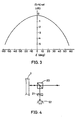
- Figure 3 shows a calculated S/N ratio depending on the phase shift 6 when the polarized beam is applied to an optical system of Figure 4.
- a polarization beam splitter 20 has the following characteristics.
- the optical system of Figure 4 includes the polarization beam splitter 20, an analyzer 21, and a light detecting element 22. It will be clear from Figure 3 that the phase shift 5 between the P-wave and S-wave reflected at the polarization beam splitter 20 must be held in the following condition in order to obtain a sufficient S/N ratio.
- the calculation result of Figure 3 is a relative S/N ratio when the direction of the analyzer 21 is set to ensure the maximum S/N ratio.
- a similar S/N ratio is obtained when the direction of the analyzer 21 is set at the middle (45°) of the S-direction and the P-direction.
- the S/N ratio further deteriorates when the extinction ratio of the optical system deteriorates. That is, the phase shift 5 of the polarization beam splitter must be strictly controlled. Moreover, the phase shift 6 must be properly controlled not only at the polarization beam splitters 5 and 8 but also at the remaining optical components such as the total reflection prism 6.
- the magneto-optic rotation angle is increased, and the reproduction operation is effectively conducted. Since the rotation angle is increased, the azimuth of the analyzer can be selected at a large value. Accordingly, the S/N ratio is hardly influenced by the extinction ratio of the optical components. That is, a desirable reproduction is carried out.
- the main purpose of the polarization beam splitters 5 and 8 is to minimize the deterioration of the information beam reflected from the recording medium 1.
- the detection unit includes an element having the amplifying function such as a photomultiplier or an APD (Avalanche Photo Diode)
- the main noise source is the optical shot noise.
- the S/N ratio can be represented as follows.
- the optical characteristic rp and r s must satisfy the following condition in order to minimize the deterioration of the S/N ratio when the beam has the magneto-optic rotation angle ⁇ o before it is introduced into the polarization beam splitter.
- the optical characteristics should be selected such that the product in the light intensity and the magneto-optic rotation angle after the beam is developed from the polarization beam splitter approximates to that before the beam is introduced into the polarization beam splitter.
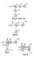
- Figure 5 shows a conventional optical head which utilizes the differential reproduction method.
- the conventional system includes a half mirror 30, and analyzers 31 and 32.
- the analyzers 31 and 32 totally reflect the S-polarization, and totally transmit the P-polarization.
- Light responsive elements 33 and 34 are disposed to detect the reproduced beam.
- the information beams divided by the half mirror 30 are detected, respectively, and differentially reproduced.
- the polarization condition of the information beam divided by the half mirror is not determinative.
- Figure 6 shows an optical system related to the present invention.
- An analyzer 35 polarization beam splitter
- Light responsive elements 36 and 37 are disposed to detect the beam developed from the analyzer 35.
- the difference of the modulation factor is not observed when the azimuth of the analyzer 35 is selected at 45°.
- the signal modulation factor is relatively small and, thus, the S/N ratio is not so high in a specific case when the azimuth of the analyzer is selected at a large value.
- the modulation factor should be improved by employing the above-discussed polarization beam splitters 5 and 8, and increasing the magneto-optic rotation angle of the information beam applied to the analyzer 35.
- the neutral polarization direction of the information beam is adjusted at the middle (45°) of the S-axis and the P-axis of the analyzer by rotating the analyzer 35 (polarization beam splitter) by 45° when it is installed in the optical system.
- a half-wave plate 38 is disposed in front of the analyzer 35 so as to set the fast axis (slow axis) suited for rotating the plane of polarization in a desired direction.
- polarization beam splitter PBS
- DAD digital audio disc
- a plurality of polarization beam splitters 39 are coupled to form an analyser as shown in Figures 7 and 8.
- Light responsive elements 40 and 41 are disposed to detect the beam applied from the analyzer.
Claims (5)



Applications Claiming Priority (2)
| Application Number | Priority Date | Filing Date | Title |
|---|---|---|---|
| JP210370/83 | 1983-11-08 | ||
| JP58210370A JP2504734B2 (ja) | 1983-11-08 | 1983-11-08 | 光磁気記憶装置の光学装置 |
Publications (3)
| Publication Number | Publication Date |
|---|---|
| EP0141679A2 EP0141679A2 (fr) | 1985-05-15 |
| EP0141679A3 EP0141679A3 (en) | 1986-06-04 |
| EP0141679B1 true EP0141679B1 (fr) | 1990-07-04 |
Family
ID=16588232
Family Applications (1)
| Application Number | Title | Priority Date | Filing Date |
|---|---|---|---|
| EP84307685A Expired EP0141679B1 (fr) | 1983-11-08 | 1984-11-07 | Système optique pour un dispositif de mémoire magnéto-optique |
Country Status (5)
| Country | Link |
|---|---|
| US (1) | US4721368A (fr) |
| EP (1) | EP0141679B1 (fr) |
| JP (1) | JP2504734B2 (fr) |
| CA (1) | CA1223349A (fr) |
| DE (1) | DE3482640D1 (fr) |
Families Citing this family (30)
| Publication number | Priority date | Publication date | Assignee | Title |
|---|---|---|---|---|
| JPH0622070B2 (ja) * | 1983-12-29 | 1994-03-23 | オリンパス光学工業株式会社 | 光磁気ピツクアツプ装置 |
| JPS60151855A (ja) * | 1984-01-20 | 1985-08-09 | Olympus Optical Co Ltd | 光磁気ピツクアツプ装置 |
| JPS61160852A (ja) * | 1984-12-30 | 1986-07-21 | Olympus Optical Co Ltd | 光磁気ピツクアツプ装置 |
| US4853923A (en) * | 1985-12-12 | 1989-08-01 | Nikon Corporation | Maneto-optical recording apparatus with path length compensated dual photo-electric conversion |
| EP0226647B1 (fr) * | 1985-12-17 | 1991-05-29 | Ibm Deutschland Gmbh | Tête de lecture/écriture pour disques optiques |
| US4863246A (en) * | 1986-08-14 | 1989-09-05 | Optical Coating Laboratory, Inc. | Optical system and components for optical disk reader |
| US4813032A (en) * | 1986-10-17 | 1989-03-14 | Canon Kabushiki Kaisha | Magneto-optical information reproducing apparatus in which the azimuth angle of the transmission axis of an analyzer is optimized so that the C/N ratio of a reproducing signal is maximum |
| US4918675A (en) * | 1986-12-04 | 1990-04-17 | Pencom International Corporation | Magneto-optical head with separate optical paths for error and data detection |
| US4905216A (en) * | 1986-12-04 | 1990-02-27 | Pencom International Corporation | Method for constructing an optical head by varying a hologram pattern |
| JPS63102031U (fr) * | 1986-12-22 | 1988-07-02 | ||
| DE3802538A1 (de) * | 1987-01-28 | 1988-08-11 | Olympus Optical Co | Vorrichtung zum erfassen von fotomagnetischen signalen |
| JPH073710B2 (ja) * | 1987-06-17 | 1995-01-18 | 日本電気株式会社 | 光磁気ディスク装置 |
| JPS6417247A (en) * | 1987-07-10 | 1989-01-20 | Nippon Telegraph & Telephone | Optical head |
| US5199013A (en) * | 1989-01-18 | 1993-03-30 | Teac Corporation | Optical head apparatus applicable to optical disc apparatus |
| JPH02287932A (ja) * | 1989-04-28 | 1990-11-28 | Toshiba Corp | 光学ヘッド |
| JP2982965B2 (ja) * | 1989-09-18 | 1999-11-29 | オリンパス光学工業株式会社 | 光学式読み取り装置 |
| JPH0435222U (fr) * | 1990-07-23 | 1992-03-24 | ||
| US5119352A (en) * | 1990-08-17 | 1992-06-02 | Hewlett-Packard Company | Magneto optic data storage read out apparatus and method |
| US5218582A (en) * | 1990-12-03 | 1993-06-08 | Eastman Kodak Company | Magneto-optic readout using a polarization-preserving optical guide |
| JPH04301245A (ja) * | 1991-03-28 | 1992-10-23 | Canon Inc | 光磁気記録再生用光ヘッド |
| US5309422A (en) * | 1991-06-10 | 1994-05-03 | Alps Electric Co., Ltd. | Light separation element and light receiving optical device using same |
| US5241523A (en) * | 1991-12-05 | 1993-08-31 | Eastman Kodak Company | Polarization-based auto-focus apparatus |
| JPH06176426A (ja) * | 1992-12-08 | 1994-06-24 | Sony Corp | 光学ピックアップ装置 |
| US5550798A (en) * | 1993-04-13 | 1996-08-27 | Sony Corporation | Enhanced optical beam splitter to increase the kerr rotation angle |
| KR950703164A (ko) * | 1993-06-25 | 1995-08-23 | 에프.제이. 스미트 | 극성화 빔 스플리터와 이를 사용하는 마그네토-광학적 판독 디바이스(Polarizing beam splitter and magneto-optic reading device using the same) |
| JP3541893B2 (ja) * | 1993-08-06 | 2004-07-14 | ソニー株式会社 | 光磁気記録媒体再生装置 |
| TW304232B (en) * | 1996-11-23 | 1997-05-01 | Ind Tech Res Inst | The wide band polarizer with multi-layers film |
| JP5813959B2 (ja) * | 2011-02-07 | 2015-11-17 | 株式会社ディスコ | レーザー光線照射機構およびレーザー加工装置 |
| US10712775B2 (en) * | 2016-12-06 | 2020-07-14 | Facebook Technologies, Llc | Dichroic combiner backlight used in a head mounted display |
| CN120629024A (zh) * | 2025-08-13 | 2025-09-12 | 杭州纳境科技有限公司 | 基于超表面的磁光成像系统及其设计方法 |
Family Cites Families (10)
| Publication number | Priority date | Publication date | Assignee | Title |
|---|---|---|---|---|
| US3594064A (en) * | 1969-06-25 | 1971-07-20 | Du Pont | Enhanced magneto-optic mirror apparatus |
| NL7506495A (nl) * | 1975-06-02 | 1976-12-06 | Philips Nv | Inrichting voor het uitlezen van een registratie- drager. |
| JPS57111843A (en) * | 1980-12-27 | 1982-07-12 | Canon Inc | Vertical magnetic reading optical system |
| JPS57200958A (en) * | 1981-06-02 | 1982-12-09 | Canon Inc | Recording pattern reading opticl system |
| JPS57205840A (en) * | 1981-06-10 | 1982-12-17 | Canon Inc | Vertical magnetic recording and reproducing device |
| JPS5814330A (ja) * | 1981-07-17 | 1983-01-27 | Matsushita Electric Ind Co Ltd | 光学装置 |
| JPH0756709B2 (ja) * | 1981-10-29 | 1995-06-14 | シャ−プ株式会社 | 光磁気記憶装置 |
| CA1190321A (fr) * | 1981-10-29 | 1985-07-09 | Toshihisa Deguchi | Tete magneto-optique |
| JPS58122633A (ja) * | 1982-01-18 | 1983-07-21 | Sharp Corp | 光学装置 |
| US4516837A (en) * | 1983-02-22 | 1985-05-14 | Sperry Corporation | Electro-optical switch for unpolarized optical signals |
-
1983
- 1983-11-08 JP JP58210370A patent/JP2504734B2/ja not_active Expired - Lifetime
-
1984
- 1984-11-02 CA CA000466947A patent/CA1223349A/fr not_active Expired
- 1984-11-06 US US06/668,796 patent/US4721368A/en not_active Expired - Lifetime
- 1984-11-07 DE DE8484307685T patent/DE3482640D1/de not_active Expired - Lifetime
- 1984-11-07 EP EP84307685A patent/EP0141679B1/fr not_active Expired
Also Published As
| Publication number | Publication date |
|---|---|
| CA1223349A (fr) | 1987-06-23 |
| US4721368A (en) | 1988-01-26 |
| EP0141679A3 (en) | 1986-06-04 |
| DE3482640D1 (de) | 1990-08-09 |
| JPS60101745A (ja) | 1985-06-05 |
| JP2504734B2 (ja) | 1996-06-05 |
| EP0141679A2 (fr) | 1985-05-15 |
Similar Documents
| Publication | Publication Date | Title |
|---|---|---|
| EP0141679B1 (fr) | Système optique pour un dispositif de mémoire magnéto-optique | |
| US4571650A (en) | Magneto-optic information storage system utilizing a self-coupled laser | |
| EP0176271B1 (fr) | Appareil d'entraînement pour milieu de mémoire optique | |
| EP0522500B1 (fr) | Dispositif de tête optique | |
| US5187703A (en) | Magneto-optical multilayer recording disk and method of reproducing the same | |
| US4638470A (en) | Apparatus using beam splitter cube with specific characteristics for reading information recorded in a magneto-optic medium | |
| US3474428A (en) | Magneto-optical reproducer | |
| CA1326548C (fr) | Element de memoire magneto-optique | |
| US5898661A (en) | Optical information storage unit | |
| EP0908872B1 (fr) | Unité de stockage d'information optique | |
| US6229783B1 (en) | Optical recording device having a medium with two superimposed levels and method for reading | |
| US4639816A (en) | Magneto-optical recording medium | |
| JPS6255222B2 (fr) | ||
| JP2511202B2 (ja) | 光学装置 | |
| JPH0756709B2 (ja) | 光磁気記憶装置 | |
| JPS60113347A (ja) | 光磁気記憶装置の光学装置 | |
| JPS6273442A (ja) | 磁気光学記憶素子 | |
| JP2510131B2 (ja) | 光磁気記憶装置 | |
| EP0621591B1 (fr) | Milieu d'enregistrement optique et dispositif de sa reproduction | |
| KR100357094B1 (ko) | 근접장 광자기 기록/재생 장치 및 방법 | |
| JP2859519B2 (ja) | 光情報再生装置 | |
| JPH08212615A (ja) | 光磁気記憶装置の光学装置 | |
| JPS62172550A (ja) | 光磁気記録媒体用ピツクアツプ | |
| JPH0247017B2 (ja) | Jikikogakuhetsudo | |
| JPH0785514A (ja) | 光記録媒体及び光記録媒体再生装置 |
Legal Events
| Date | Code | Title | Description |
|---|---|---|---|
| PUAI | Public reference made under article 153(3) epc to a published international application that has entered the european phase |
Free format text: ORIGINAL CODE: 0009012 |
|
| AK | Designated contracting states |
Designated state(s): DE FR GB IT |
|
| PUAL | Search report despatched |
Free format text: ORIGINAL CODE: 0009013 |
|
| AK | Designated contracting states |
Kind code of ref document: A3 Designated state(s): DE FR GB IT |
|
| 17P | Request for examination filed |
Effective date: 19860929 |
|
| 17Q | First examination report despatched |
Effective date: 19880707 |
|
| ITF | It: translation for a ep patent filed | ||
| GRAA | (expected) grant |
Free format text: ORIGINAL CODE: 0009210 |
|
| AK | Designated contracting states |
Kind code of ref document: B1 Designated state(s): DE FR GB IT |
|
| REF | Corresponds to: |
Ref document number: 3482640 Country of ref document: DE Date of ref document: 19900809 |
|
| ET | Fr: translation filed | ||
| PLBE | No opposition filed within time limit |
Free format text: ORIGINAL CODE: 0009261 |
|
| STAA | Information on the status of an ep patent application or granted ep patent |
Free format text: STATUS: NO OPPOSITION FILED WITHIN TIME LIMIT |
|
| 26N | No opposition filed | ||
| ITTA | It: last paid annual fee | ||
| REG | Reference to a national code |
Ref country code: GB Ref legal event code: IF02 |
|
| PGFP | Annual fee paid to national office [announced via postgrant information from national office to epo] |
Ref country code: GB Payment date: 20031105 Year of fee payment: 20 |
|
| PGFP | Annual fee paid to national office [announced via postgrant information from national office to epo] |
Ref country code: FR Payment date: 20031110 Year of fee payment: 20 |
|
| PGFP | Annual fee paid to national office [announced via postgrant information from national office to epo] |
Ref country code: DE Payment date: 20031120 Year of fee payment: 20 |
|
| PG25 | Lapsed in a contracting state [announced via postgrant information from national office to epo] |
Ref country code: GB Free format text: LAPSE BECAUSE OF EXPIRATION OF PROTECTION Effective date: 20041106 |
|
| REG | Reference to a national code |
Ref country code: GB Ref legal event code: PE20 |