EP0142001A1 - Dispositif assorti pour lier un faisceau de lignes électriques - Google Patents
Dispositif assorti pour lier un faisceau de lignes électriques Download PDFInfo
- Publication number
- EP0142001A1 EP0142001A1 EP84111771A EP84111771A EP0142001A1 EP 0142001 A1 EP0142001 A1 EP 0142001A1 EP 84111771 A EP84111771 A EP 84111771A EP 84111771 A EP84111771 A EP 84111771A EP 0142001 A1 EP0142001 A1 EP 0142001A1
- Authority
- EP
- European Patent Office
- Prior art keywords
- thread
- needle
- bundle
- loop
- cutting knife
- Prior art date
- Legal status (The legal status is an assumption and is not a legal conclusion. Google has not performed a legal analysis and makes no representation as to the accuracy of the status listed.)
- Granted
Links
- 238000000034 method Methods 0.000 claims abstract description 55
- 238000005520 cutting process Methods 0.000 claims abstract description 40
- 230000015572 biosynthetic process Effects 0.000 claims description 3
- 230000002441 reversible effect Effects 0.000 claims description 2
- 238000006073 displacement reaction Methods 0.000 claims 1
- 238000000926 separation method Methods 0.000 claims 1
- 238000004804 winding Methods 0.000 description 12
- 210000002105 tongue Anatomy 0.000 description 10
- 230000003993 interaction Effects 0.000 description 4
- 230000006835 compression Effects 0.000 description 3
- 238000007906 compression Methods 0.000 description 3
- 241001295925 Gegenes Species 0.000 description 1
- 230000005540 biological transmission Effects 0.000 description 1
- 230000000903 blocking effect Effects 0.000 description 1
- 239000004020 conductor Substances 0.000 description 1
- 230000000694 effects Effects 0.000 description 1
- 238000005516 engineering process Methods 0.000 description 1
- 239000000463 material Substances 0.000 description 1
- 238000009751 slip forming Methods 0.000 description 1
Images


Classifications
-
- H—ELECTRICITY
- H01—ELECTRIC ELEMENTS
- H01B—CABLES; CONDUCTORS; INSULATORS; SELECTION OF MATERIALS FOR THEIR CONDUCTIVE, INSULATING OR DIELECTRIC PROPERTIES
- H01B13/00—Apparatus or processes specially adapted for manufacturing conductors or cables
- H01B13/012—Apparatus or processes specially adapted for manufacturing conductors or cables for manufacturing wire harnesses
- H01B13/01263—Tying, wrapping, binding, lacing, strapping or sheathing harnesses
- H01B13/01272—Harness tying apparatus
Definitions
- the invention relates to a method for tying a bundle of electrical lines according to the preamble of claim 1 and to an associated device according to the preamble of claim 7.
- a method and a device of the type mentioned above are specified in detail in DE-OS 25 33 640.
- the device described there it is particularly especially possible to machine and continuously wrap a wire harness, with a stability of the thread package created should be achieved by a double thread in each case during the loop formation.
- knotting and cutting off the twine with this device is not possible, so that fully automatic operation is not achieved.
- the latter peculiarity of the device previously known from DE-OS 25 33 640 is regarded by the experts as disadvantageous since practical work cannot be achieved.
- a device for performing this method is characterized by the characterizing features of patent claim 7.
- the device implemented according to the new device can be held like a pistol in one hand during the entire workflow and can be guided to the desired binding point with its gripper the. Since the new process itself works discontinuously, i.e. on the one hand the thread end of the twine is cut off after looping and knotting, but on the other hand the continuous end of the twine is held, binding can be carried out at certain points, for which the device can be freely guided to the cable harness.
- the invention does not implement a continuous looping process of the parallel lines, along which the device had to be moved along as evenly as possible, but rather is bound to discrete locations of the lines. This results in much larger possible uses.
- a continuous crochet structure also had the disadvantage that when the loop was broken at one point, the entire crochet structure was dissolved over the continuous area.
- a double looping process with subsequent double knots is preferably carried out at the binding point, the thread end being pulled through the knot structure after cutting to catch. The binding, knotting, cutting and catching of the thread now form a single, completed work cycle.
- a cutting knife and a catching needle are guided in such a way that the looping and knotting with the latch needle and then cutting and catching takes place in chronological succession.
- the drive is preferably controlled by compressed air and the control is constructed mechanically. However, an electrical / electronic drive control is also possible.
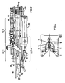
- 100 denotes the housing of a device for tying parallel lines, such as, for example, cable harnesses or the like, which is referred to below as a winding gun.
- a winding gun The designation "winding pistol” already makes it clear that the housing can be held by the user with one hand on a housing knob 105, brought into the correct working position and put into operation via an actuating lever 106.
- the entire winding gun is so compact that it can be brought into the respective operating position without difficulty even in tight working conditions. It is possible to guide the winding gun along a cable harness manually or mechanically, in particular robot-guided.
- the housing 100 of the winding gun essentially consists of two parallel housing plates 110 and 111 which are connected at a distance and on which the working equipment and the necessary operating resources are arranged.
- Backwards can be a supply roll for Twine can be arranged, from which a thread 2 is brought into the working area on the front part of the housing 100 via corresponding guides.
- a thread tensioning and return device 120 provides the necessary tension in the thread.
- the working area is designed with a guide 3 for the thread 2 and a gripper 130 such that a bundle of parallel lines can be wrapped around the thread 2.
- the gripper 130 is roughly horseshoe-shaped and is guided by a gear transmission. It can be swiveled by approximately + 90 ° to ensure that a wire harness with its cross-section lies in the horseshoe profile.
- the needle 4 is referred to as a "tongue needle” because of a driving tongue for the thread 2.
- a forward and backward movement of the latch needle 4 is possible via an associated holder 5 and drive 140 with a compressed air cylinder.
- the holder 5 of the latch needle 4 is equally guided, so that, in addition to the higher-level forward and backward movement, there is also a movement in a predetermined curve shape.
- corresponding guide plates 131 and 132 are provided on the housing plates 110 and 111 in the area of the gripper 130.
- the basic form of the winding pistol which can be seen in FIG. 1 is essentially known from DE-OS 25 33 640.
- latch needle 4 and gripper 130 the interaction of latch needle 4 and gripper 130 is described in detail, wherein loops for looping the parallel lines are continuously formed there. After the looping processes to form a braid along the extended cable harness, the twine must be cut off there and the end of the thread must be knotted manually.
- the winding gun has additional work tools which are attached to the side of the housing plate 111.
- These are essentially a cutting knife 17 and a so-called catch needle 18, both of which can likewise perform a forward and backward movement via a drive 160 with a pressure cylinder.
- the movement takes place in the direction of the housing plate 111, which can be seen from the groove profile shown.
- the pressure medium-actuated drive units 140 and 160 are coupled to one another in the sense of a time delay in the movement sequence, which will be explained further below.
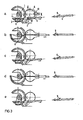
- 1 represents an already bound conductor bundle.
- 2 identify the twine
- 3 a thread guide device
- 4 the latch needle
- 5 the associated holder
- 6 the link wheel
- 10 the associated link guide.
- the assignment of these details to FIG 1 is clearly recognizable.
- the position of the associated tongue 9 is indicated for the tongue needle 4.
- the device shown is initially used in a manner known per se for tying a wire harness.
- the bracket 5 is alternately pushed back and forth in the lower or upper groove of the link guide 10, the looping of the wire harness with the thread 2 interacting with the gripper 130 results.
- the upper guide half of the link guide 10 is locked for the knot, so that the latch needle 4 can now only move back and forth in the groove of the lower guide halves.
- FIG. 3a shows that the thread 2 runs over the thread guide 3 around the line bundle 1 and forms a loop 8 through which the latch needle is guided.
- the gripper 130 is in the starting position.
- the latch needle 4 is at open tongue 9 carried the twine and pulled as a loop 7 through the last loop 8 present from the binding process.
- the link wheel 6 moves in the opposite direction, so that a position according to FIG. 3b results.
- the tongue 9 of the latch needle 4 is now closed, which can be achieved by the thread pressure if the latch needle 4 is designed accordingly.
- FIG. 3c the tongue 9 opening when moving forward and the tongue needle 4 then moving through the newly formed loop into a position according to FIG. 3a.
- Corresponding substeps according to FIG. 3d and FIG. 3e follow, which in principle correspond to the substeps according to FIG. 3b and FIG. 3c, so that the result is a structure with several loops.
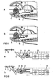
- the associated connecting link guide is shown in detail: it consists essentially of a mounting plate 11 having formed in two guide halves cam groove 10, a pin 12 for guiding the holding ß incardi, 5 for the latch needle 4, a Umschaltzunge 13, a Locking lever 14 and a further pin 15.
- needle 4 executes such a path, which is described in FIG. 4 by points I via II to III and from III to II to back to I, path II to III is blocked during the knotting process, for example.
- the pin 12 and the latch needle 4 thus follow the direct path from I to II and back again from II to I.
- the latter movement defines a loop which can be tightened into a knot and can be repeated as required.
- the setting is blocked by the switching tongue 13, which is pressed upward by the locking lever 14, the locking lever 14 acting directly on the pin 15.
- the thread 2 of the twine is to be tightened and cut in a defined position, it being necessary to ensure that the cut thread can be caught and is thus immediately available for a new binding process.
- the kinematics of cutting off on the one hand and catching the thread end on the other hand are explained in various working phases with reference to FIGS. 5 and 6 on the one hand and FIGS. 7 and 8 on the other hand.
- 16 means the knot to be formed, 17 the cutting knife, 18 the catching needle, 19 the associated holder, 20 a pin on the knife holder, 21 an associated link for guiding the cutting knife 17 and catching needle 18, 22 a compressed air cylinder, 23 a clamping pin, 24 an elbow, 25 a spring, 26 a needle opening and 28 a stop for the catching needle 18.
- FIG. 5a and 6a are in their rest position
- FIG. 5b and FIG. 6b show their position immediately after the cutting process.
- the blade 17 is brought along the slide guide 21 into the plane of the latch needle 4, the thread being cut off directly at the knot 16.
- the catching needle 18 is present, the shape and function of which becomes clear from FIGS. 7 and 8.
- the sectional view of FIG. 8a shows their comparatively complex structure with inner clamping pin 23, inner spring 25 and an outer pin 27 which is resiliently mounted via an angle piece 24.
- the clamping pin 23 is firmly connected to the angle 24 and is pressed forward by the spring 25, so that a thread 2 can be firmly clamped in the needle opening 26.
- the inner spring pin 27 also serves to support the clamping process.
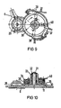
- the latter can be done in one embodiment of the invention in connection with a compressed air drive by a cam control, which is illustrated by the description of FIG. 9 to FIG. 11.
- the cam control is driven via the link wheel 6, which is rotated in a known manner during the forward and backward movement of the latch needle 4 to the left or right.
- a drive gear 29, which serves to drive an associated control gear 30, is fastened concentrically to the sliding gear 6. Its fixed axis 31 is screwed to the holding plate 11 of FIG. 4.
- a freewheel 32 is seated in the axis of the control gear 30, which only allows clockwise rotation of the switching disks 34, 35 and 36 which are jointly fastened on a bushing 33.
- the translation between the gears 29 and 30 is selected so that a working cycle is completed when the disks 34, 35 and 36 are rotated through 360 °. This working cycle includes the binding, knotting, cutting and catching or holding process for the twine.
- the switching disc 34 saw-toothed at the circumference notches that an angular distance of 2 x 90 ° for a two-time binding operation, an angular distance of 2 x 45 ° for a two-time node operation and another 90 0 hold for the zero position.
- a spring-loaded pawl 37 can snap into the notches. The pawl 37 is used for the exact fixing of the switching disks 34, 35 and 36 and thus prevents turning back when the directional gear 6 changes direction.
- the switching disk 35 in FIG. 11 is necessary for the knotting process if, as has been shown above, the blocking of the path II to III in the link guide 10 is to be effected in the angular range of 2 ⁇ 45 °.
- the switching disk 36 with pawl 39 is used to stop the binding device. A reversing slide can be blocked via the pawl 39 and the operating function of the device described can thus be stopped.
- the drive and control takes place on a pneumatic / mechanical basis. It is also possible to provide the drive electrically and to create an electronic sequence control.
- a microprocessor system can expediently be used here.
Landscapes
- Engineering & Computer Science (AREA)
- Manufacturing & Machinery (AREA)
- Basic Packing Technique (AREA)
- Insertion, Bundling And Securing Of Wires For Electric Apparatuses (AREA)
Priority Applications (1)
| Application Number | Priority Date | Filing Date | Title |
|---|---|---|---|
| AT84111771T ATE29797T1 (de) | 1983-10-18 | 1984-10-02 | Vorrichtung zum binden eines buendels elektrischer leitungen. |
Applications Claiming Priority (2)
| Application Number | Priority Date | Filing Date | Title |
|---|---|---|---|
| DE3337853 | 1983-10-18 | ||
| DE19833337853 DE3337853A1 (de) | 1983-10-18 | 1983-10-18 | Verfahren zum binden eines buendels elektrischer leitungen sowie zugehoerige vorrichtung |
Publications (2)
| Publication Number | Publication Date |
|---|---|
| EP0142001A1 true EP0142001A1 (fr) | 1985-05-22 |
| EP0142001B1 EP0142001B1 (fr) | 1987-09-16 |
Family
ID=6212129
Family Applications (1)
| Application Number | Title | Priority Date | Filing Date |
|---|---|---|---|
| EP84111771A Expired EP0142001B1 (fr) | 1983-10-18 | 1984-10-02 | Dispositif assorti pour lier un faisceau de lignes électriques |
Country Status (4)
| Country | Link |
|---|---|
| US (1) | US4558894A (fr) |
| EP (1) | EP0142001B1 (fr) |
| AT (1) | ATE29797T1 (fr) |
| DE (2) | DE3337853A1 (fr) |
Cited By (1)
| Publication number | Priority date | Publication date | Assignee | Title |
|---|---|---|---|---|
| WO1987004683A1 (fr) * | 1986-01-30 | 1987-08-13 | Komax Ag | Outil de ficelage de faisceaux de cables |
Families Citing this family (15)
| Publication number | Priority date | Publication date | Assignee | Title |
|---|---|---|---|---|
| MY130074A (en) * | 1992-02-28 | 2007-05-31 | Bentac Co Ltd | Method and apparatus for tying one more articles |
| GB2317188B (en) | 1996-09-14 | 2000-06-14 | Bentley Harris Sa | Wiring harness bundling |
| US6944932B2 (en) * | 1999-08-27 | 2005-09-20 | Giovanni Fortuna | Method for making a self-locking knot in a stator lacing machine |
| EP1081831B1 (fr) * | 1999-09-06 | 2003-04-09 | Giovanni Fortuna | Procédé et dispositif pour la réalisation d'un noeud se refermant de lui-meme dans une machine de laçage de stators |
| US6279970B1 (en) | 2000-06-20 | 2001-08-28 | Michael Torres | Automatic knot-tying device |
| US6648378B1 (en) | 2002-10-04 | 2003-11-18 | Via Science Llc | Automatic knot-tying device |
| KR100804960B1 (ko) * | 2007-03-29 | 2008-02-20 | 이덕희 | 택 부착기의 매듭기의 교체장치 |
| ATE549914T1 (de) | 2009-05-06 | 2012-04-15 | Qimas E U | Portable bindemaschine |
| US8622440B2 (en) * | 2010-10-05 | 2014-01-07 | Ideal Industries, Inc. | Knot tying device and cartridge system for providing tying filament thereto |
| US9433198B2 (en) * | 2014-03-06 | 2016-09-06 | Phyllis D. O'Neal | Fishing line knotter |
| EP3133913B1 (fr) | 2014-04-24 | 2020-02-26 | Cruzzolin, Andrea | Appareil et méthode opérationnelle correspondante pour lier automatiquement ensemble au moins deux éléments |
| JP6803151B2 (ja) * | 2016-05-02 | 2020-12-23 | 東和精工株式会社 | 下げ札装着機 |
| US11970297B2 (en) | 2018-12-18 | 2024-04-30 | The Boeing Company | System, device and method to facilitate tying a knot |
| US11375702B2 (en) * | 2019-04-26 | 2022-07-05 | Nathanael Wills | Knot tying device |
| CN110924205A (zh) * | 2019-11-29 | 2020-03-27 | 李跃 | 一种钢丝绳绳头固定用铁丝缠绕器 |
Citations (4)
| Publication number | Priority date | Publication date | Assignee | Title |
|---|---|---|---|---|
| US3700010A (en) * | 1971-06-17 | 1972-10-24 | Us Army | Wire tying apparatus including demountable tying mechanism |
| DE2228162A1 (de) * | 1972-06-09 | 1974-01-03 | Goodwill Automated Devices Inc | Vorrichtung zum abbinden von kabelstraengen o. dgl |
| DE2533640A1 (de) * | 1975-07-28 | 1977-02-03 | Boris Sergeevitsch Egorov | Verfahren zum binden einer gruppe paralleler elektrischer leitungen, einrichtung zur durchfuehrung dieses verfahrens und nach diesem verfahren gebundene elektrische sammelleitung |
| DE2705418A1 (de) * | 1976-02-21 | 1977-09-01 | Max Co Ltd | Automatischer binder |
Family Cites Families (2)
| Publication number | Priority date | Publication date | Assignee | Title |
|---|---|---|---|---|
| US3252723A (en) * | 1964-03-02 | 1966-05-24 | United Shoe Machinery Corp | Cable lacing methods |
| US3670783A (en) * | 1970-11-04 | 1972-06-20 | Goodwill Automated Devices Inc | Cable tying machine |
-
1983
- 1983-10-18 DE DE19833337853 patent/DE3337853A1/de not_active Withdrawn
-
1984
- 1984-10-02 DE DE8484111771T patent/DE3466311D1/de not_active Expired
- 1984-10-02 EP EP84111771A patent/EP0142001B1/fr not_active Expired
- 1984-10-02 AT AT84111771T patent/ATE29797T1/de not_active IP Right Cessation
- 1984-10-18 US US06/662,180 patent/US4558894A/en not_active Expired - Fee Related
Patent Citations (4)
| Publication number | Priority date | Publication date | Assignee | Title |
|---|---|---|---|---|
| US3700010A (en) * | 1971-06-17 | 1972-10-24 | Us Army | Wire tying apparatus including demountable tying mechanism |
| DE2228162A1 (de) * | 1972-06-09 | 1974-01-03 | Goodwill Automated Devices Inc | Vorrichtung zum abbinden von kabelstraengen o. dgl |
| DE2533640A1 (de) * | 1975-07-28 | 1977-02-03 | Boris Sergeevitsch Egorov | Verfahren zum binden einer gruppe paralleler elektrischer leitungen, einrichtung zur durchfuehrung dieses verfahrens und nach diesem verfahren gebundene elektrische sammelleitung |
| DE2705418A1 (de) * | 1976-02-21 | 1977-09-01 | Max Co Ltd | Automatischer binder |
Cited By (1)
| Publication number | Priority date | Publication date | Assignee | Title |
|---|---|---|---|---|
| WO1987004683A1 (fr) * | 1986-01-30 | 1987-08-13 | Komax Ag | Outil de ficelage de faisceaux de cables |
Also Published As
| Publication number | Publication date |
|---|---|
| ATE29797T1 (de) | 1987-10-15 |
| DE3466311D1 (en) | 1987-10-22 |
| EP0142001B1 (fr) | 1987-09-16 |
| US4558894A (en) | 1985-12-17 |
| DE3337853A1 (de) | 1985-04-25 |
Similar Documents
| Publication | Publication Date | Title |
|---|---|---|
| EP0142001B1 (fr) | Dispositif assorti pour lier un faisceau de lignes électriques | |
| DE2700641C3 (de) | Verpackungshüllenabschnitt mit einer Aufhängeschtaufe und Verfahren und Vorrichtung zum Anbringen derselben | |
| DE2720027C3 (de) | Bindewerkzeug zum Verdrillen der freien Enden eines Bindedrahtes | |
| DE69606943T2 (de) | Maschine zur herstellung von aufgussbeuteln, die mittels verbindungsfäden befestigte anhänger aufweisen | |
| EP0084680B1 (fr) | Appareil pour lier des balles dans une presse à balles | |
| DE69305197T2 (de) | Verfahren und Vorrichtung zum Umschnüren von einem oder mehreren Gegenständen | |
| DE3202233C2 (de) | Vorrichtung zum Umschnüren von Ballen | |
| DE2243210C3 (de) | Verfahren zum Bewickeln von Kollektorankern elektrischer Maschinen | |
| DE1032380B (de) | Ankerwickelmaschine fuer Anker elektrischer Maschinen mit auf einer Welle befestigtem genutetem Ankerkern und Kommutator | |
| DE10308432A1 (de) | Verfahren und Vorrichtung zur maschinellen Herstellung von spulenlosen Kabelwickeln | |
| DE2105163C3 (de) | Maschine zum Pressen und Umschnüren von Ballen mit Draht | |
| DE3121934C2 (fr) | ||
| DE2437452A1 (de) | Vorrichtung und verfahren zum schnueren bzw. binden von spulen | |
| DE2825151A1 (de) | Vorrichtung zum intermittierenden bilden einer drahtflechte aus einem ohne unterbrechung zugefuehrten einzeldraht | |
| DE68920287T2 (de) | Bindemechanismus mit umlaufendem Führungsring. | |
| DE2313719A1 (de) | Drahtschlingvorrichtung | |
| DE3006537A1 (de) | Spulenwickelmaschine | |
| DE2833257A1 (de) | Verfahren zum ballenpressen und ballenpresse fuer heu, stroh u.dgl. | |
| DE2725511C2 (de) | Einrichtung zur Verstärkung eines Spulendrahtabschnittes | |
| DE1909747C3 (de) | Gerät zum Fädeln von Fadenmaterial durch mindestens eine öffnung eines Körpers | |
| DE2803511C2 (de) | Vorrichtung zum Vorlegen einer Aufhängeschlaufe zur Verwendung an einer Maschine zum Verschließen von Wursthüllen | |
| DE2533640A1 (de) | Verfahren zum binden einer gruppe paralleler elektrischer leitungen, einrichtung zur durchfuehrung dieses verfahrens und nach diesem verfahren gebundene elektrische sammelleitung | |
| DE2228162C2 (de) | Vorrichtung zum Abbinden von Kabelsträngen | |
| DE2553882C2 (de) | Vorrichtung zum Wickeln sattelförmiger Ablenkspulen | |
| DE3741215C2 (fr) |
Legal Events
| Date | Code | Title | Description |
|---|---|---|---|
| PUAI | Public reference made under article 153(3) epc to a published international application that has entered the european phase |
Free format text: ORIGINAL CODE: 0009012 |
|
| AK | Designated contracting states |
Designated state(s): AT DE FR GB IT NL SE |
|
| 17P | Request for examination filed |
Effective date: 19850827 |
|
| 17Q | First examination report despatched |
Effective date: 19860423 |
|
| GRAA | (expected) grant |
Free format text: ORIGINAL CODE: 0009210 |
|
| AK | Designated contracting states |
Kind code of ref document: B1 Designated state(s): AT DE FR GB IT NL SE |
|
| REF | Corresponds to: |
Ref document number: 29797 Country of ref document: AT Date of ref document: 19871015 Kind code of ref document: T |
|
| REF | Corresponds to: |
Ref document number: 3466311 Country of ref document: DE Date of ref document: 19871022 |
|
| ET | Fr: translation filed | ||
| ITF | It: translation for a ep patent filed | ||
| GBT | Gb: translation of ep patent filed (gb section 77(6)(a)/1977) | ||
| PLBE | No opposition filed within time limit |
Free format text: ORIGINAL CODE: 0009261 |
|
| STAA | Information on the status of an ep patent application or granted ep patent |
Free format text: STATUS: NO OPPOSITION FILED WITHIN TIME LIMIT |
|
| RAP2 | Party data changed (patent owner data changed or rights of a patent transferred) |
Owner name: PAUL HELLERMANN GMBH |
|
| 26N | No opposition filed | ||
| NLT2 | Nl: modifications (of names), taken from the european patent patent bulletin |
Owner name: PAUL HELLERMAN GMBH TE PINNEBERG, BONDSREPUBLIEK D |
|
| REG | Reference to a national code |
Ref country code: GB Ref legal event code: 732 |
|
| ITPR | It: changes in ownership of a european patent |
Owner name: CESSIONE;PAUL HELLERMANN GMBH |
|
| REG | Reference to a national code |
Ref country code: FR Ref legal event code: TP |
|
| NLS | Nl: assignments of ep-patents |
Owner name: PAUL HELLERMAN GMBH TE PINNEBERG, BONDSREPUBLIEK D |
|
| ITTA | It: last paid annual fee | ||
| EAL | Se: european patent in force in sweden |
Ref document number: 84111771.6 |
|
| PGFP | Annual fee paid to national office [announced via postgrant information from national office to epo] |
Ref country code: FR Payment date: 19960810 Year of fee payment: 13 |
|
| PGFP | Annual fee paid to national office [announced via postgrant information from national office to epo] |
Ref country code: GB Payment date: 19960911 Year of fee payment: 13 |
|
| PGFP | Annual fee paid to national office [announced via postgrant information from national office to epo] |
Ref country code: SE Payment date: 19961021 Year of fee payment: 13 Ref country code: AT Payment date: 19961021 Year of fee payment: 13 |
|
| PGFP | Annual fee paid to national office [announced via postgrant information from national office to epo] |
Ref country code: NL Payment date: 19961029 Year of fee payment: 13 |
|
| PGFP | Annual fee paid to national office [announced via postgrant information from national office to epo] |
Ref country code: DE Payment date: 19961220 Year of fee payment: 13 |
|
| PG25 | Lapsed in a contracting state [announced via postgrant information from national office to epo] |
Ref country code: GB Free format text: LAPSE BECAUSE OF NON-PAYMENT OF DUE FEES Effective date: 19971002 Ref country code: AT Free format text: LAPSE BECAUSE OF NON-PAYMENT OF DUE FEES Effective date: 19971002 |
|
| PG25 | Lapsed in a contracting state [announced via postgrant information from national office to epo] |
Ref country code: SE Free format text: LAPSE BECAUSE OF NON-PAYMENT OF DUE FEES Effective date: 19971003 |
|
| PG25 | Lapsed in a contracting state [announced via postgrant information from national office to epo] |
Ref country code: FR Free format text: THE PATENT HAS BEEN ANNULLED BY A DECISION OF A NATIONAL AUTHORITY Effective date: 19971031 |
|
| PG25 | Lapsed in a contracting state [announced via postgrant information from national office to epo] |
Ref country code: NL Free format text: LAPSE BECAUSE OF NON-PAYMENT OF DUE FEES Effective date: 19980501 |
|
| GBPC | Gb: european patent ceased through non-payment of renewal fee |
Effective date: 19971002 |
|
| NLV4 | Nl: lapsed or anulled due to non-payment of the annual fee |
Effective date: 19980501 |
|
| PG25 | Lapsed in a contracting state [announced via postgrant information from national office to epo] |
Ref country code: DE Free format text: LAPSE BECAUSE OF NON-PAYMENT OF DUE FEES Effective date: 19980701 |
|
| EUG | Se: european patent has lapsed |
Ref document number: 84111771.6 |
|
| REG | Reference to a national code |
Ref country code: FR Ref legal event code: ST |