EP0142050A2 - Signalkabel - Google Patents
Signalkabel Download PDFInfo
- Publication number
- EP0142050A2 EP0142050A2 EP84112384A EP84112384A EP0142050A2 EP 0142050 A2 EP0142050 A2 EP 0142050A2 EP 84112384 A EP84112384 A EP 84112384A EP 84112384 A EP84112384 A EP 84112384A EP 0142050 A2 EP0142050 A2 EP 0142050A2
- Authority
- EP
- European Patent Office
- Prior art keywords
- signal cable
- conductors
- insulated
- cable according
- individual
- Prior art date
- Legal status (The legal status is an assumption and is not a legal conclusion. Google has not performed a legal analysis and makes no representation as to the accuracy of the status listed.)
- Granted
Links
Images
Classifications
-
- H—ELECTRICITY
- H01—ELECTRIC ELEMENTS
- H01B—CABLES; CONDUCTORS; INSULATORS; SELECTION OF MATERIALS FOR THEIR CONDUCTIVE, INSULATING OR DIELECTRIC PROPERTIES
- H01B11/00—Communication cables or conductors
- H01B11/02—Cables with twisted pairs or quads
- H01B11/06—Cables with twisted pairs or quads with means for reducing effects of electromagnetic or electrostatic disturbances, e.g. screens
- H01B11/08—Screens specially adapted for reducing cross-talk
-
- H—ELECTRICITY
- H01—ELECTRIC ELEMENTS
- H01B—CABLES; CONDUCTORS; INSULATORS; SELECTION OF MATERIALS FOR THEIR CONDUCTIVE, INSULATING OR DIELECTRIC PROPERTIES
- H01B11/00—Communication cables or conductors
- H01B11/02—Cables with twisted pairs or quads
- H01B11/06—Cables with twisted pairs or quads with means for reducing effects of electromagnetic or electrostatic disturbances, e.g. screens
- H01B11/10—Screens specially adapted for reducing interference from external sources
- H01B11/1033—Screens specially adapted for reducing interference from external sources composed of a wire-braided conductor
-
- H—ELECTRICITY
- H01—ELECTRIC ELEMENTS
- H01B—CABLES; CONDUCTORS; INSULATORS; SELECTION OF MATERIALS FOR THEIR CONDUCTIVE, INSULATING OR DIELECTRIC PROPERTIES
- H01B11/00—Communication cables or conductors
- H01B11/18—Coaxial cables; Analogous cables having more than one inner conductor within a common outer conductor
- H01B11/20—Cables having a multiplicity of coaxial lines
-
- H—ELECTRICITY
- H01—ELECTRIC ELEMENTS
- H01R—ELECTRICALLY-CONDUCTIVE CONNECTIONS; STRUCTURAL ASSOCIATIONS OF A PLURALITY OF MUTUALLY-INSULATED ELECTRICAL CONNECTING ELEMENTS; COUPLING DEVICES; CURRENT COLLECTORS
- H01R13/00—Details of coupling devices of the kinds covered by groups H01R12/70 or H01R24/00 - H01R33/00
- H01R13/648—Protective earth or shield arrangements on coupling devices, e.g. anti-static shielding
- H01R13/658—High frequency shielding arrangements, e.g. against EMI [Electro-Magnetic Interference] or EMP [Electro-Magnetic Pulse]
- H01R13/6591—Specific features or arrangements of connection of shield to conductive members
- H01R13/65912—Specific features or arrangements of connection of shield to conductive members for shielded multiconductor cable
- H01R13/65918—Specific features or arrangements of connection of shield to conductive members for shielded multiconductor cable wherein each conductor is individually surrounded by shield
Definitions
- the invention relates to a signal cable, such as an amplifier cable, with two insulated conductors running alongside one another with connection elements.
- the invention relates in particular to a signal cable such as occurs in the transmission of music signals between components of a music system.
- the invention also relates to cables for the transmission of digital signals, for example in data communication.
- those with a common shielding of both conductors are used as signal cables by a surrounding shielding line which is electrically connected to one of the individual conductors on the connecting element.
- the invention is therefore based on the object of developing a signal cable of the type mentioned which has significantly better transmission properties than the known cables and in particular also avoids parasitic magnetic and / or capacitive couplings of the two individual conductors, with the associated disadvantageous pulse delays and distortions caused thereby , such as external disturbances and their influence on the individual conductors or the signals transmitted through them.
- each conductor is surrounded by its own coaxial individual shield that is insulated against it and against one another and that the individual shields are insulated from the connection elements. Due to the configuration according to the invention First a shielding of the parallel single conductors against external interference is achieved, but moreover a mutual shielding of the individual conductors and a reduction in the total capacitance of the cable, thereby reducing the mutual influence of the signal-carrying individual conductors. It is essential not only that the individual conductors are each shielded from one another to the outside and against one another, but moreover that the individual shields themselves are not electrically connected to the connecting elements and in particular also not to a single conductor, but rather are electrically insulated in every respect are.
- the design according to the invention on the one hand avoids inductive influences which prevent an undisturbed signal transmission or oppose such interference and on the other hand practically achieves a series arrangement of capacitances with the resulting reduction in the total capacitance.
- the conductors and the individual shields are jointly surrounded by an insulated overall shield, it being possible in particular in a manner known per se that the overall shield, but not the individual shields, is electrically connected to one of the connection elements.
- the individual shields are designed as bare tinned copper mesh and / or that the conductors are silver-plated.
- the overall screen could also be designed as a bare or tinned copper mesh, but according to a preferred embodiment, it is provided that the overall screen is designed as a silver-plated copper mesh.
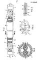
- the signal cable 1 has two individual conductors 2, 3.
- the conductors 2, 3 are connected at their ends to connecting elements 4 in the form of plugs, the conductor 2 being electrically connected to a plug socket 6 and the conductor 3 being each electrically connected to a plug pin 7 insulated from the socket 6.
- the individual conductors 2, 3 can consist, for example, of silver-plated copper strands. If the individual conductors 2, 3 have larger cross sections, for example more than 0.5 mm 2 , it is advantageous to design the conductors with individually insulated strands, the strands having, for example, PTFE insulation.
- the conductors 2, 3 are each as such surrounded by an insulating jacket 8, 9.
- a single shield 11, 12 made of electrically conductive, mesh-like shielding braid is arranged around the insulation 8, 9 coaxially with the conductors 2, 3.
- Each individual screen 11, 12 is in turn surrounded by an insulating jacket 13, 14.
- the structure of each individual conductor arrangement 2, 8, 11, 13 or 3, 9, 12, 14 described corresponds to a coaxial cable. While in a coaxial cable both the inner conductor (here, for example, 3) and the shielding braid (here, for example, 12) and a pole of a connector are connected, according to the invention, the individual shields 11, 12 end in front of the plug-in elements 4, are not connected to them, but rather opposite them Isolated.
- both individual conductor arrangements 2, 8, 11, 13 and 3, 9, 12, 14 are arranged in a common insulating inner jacket 16, which is not required for electrical engineering reasons in the illustrated embodiment of the signal cable 1 according to the invention, since each individual conductor arrangement is due to the coats 13, 14 is insulated, but is also preferable for mechanical reasons.
- the inner jacket 16 is in turn coaxially surrounded by an overall screen 17 in the form of a conductive shielding braid. To the outside there is also an outer jacket 18 which strips the entire signal cable from the outside.
- the overall screen 17 is at least one of the connecting elements te 4 and there with one of the poles 6 and 7, in the illustrated embodiment with the socket 6 electrically connected.
- the signal cable 1 according to the invention not only offers optimal shielding from external interference, but moreover in particular a reduction in the mutual influence of the signal-carrying conductors, which is the case with known signals leads to interference, distortion, etc.
- the advantages according to the invention are achieved in particular in that the shields 11, 12 themselves are not switched on in the electrical conduction process, but rather are insulated from the connection elements and only perform shielding tasks.
- the cable according to the invention is also suitable for transmission in data communication, since the embodiments according to the invention distort runtime etc. be minimized.
Landscapes
- Physics & Mathematics (AREA)
- Electromagnetism (AREA)
- Communication Cables (AREA)
- Insulated Conductors (AREA)
Abstract
Description
- Die Erfindung betrifft ein Signalkabel, wie als Verstärkerkabel, mit zwei nebeneinander verlaufenden isolierten Leitern mit Anschlußelementen.
- Die Erfindung bezieht sich insbesondere auf ein Signalkabel, wie sie bei der Übertragung von Musiksignalen zwischen Komponenten einer Musikanlage auftreten.Neben solchen Phonokabeln bezieht sich die Erfindung auch auf Kabel zur Übertragung digitaler Signale, beispielsweise in der Datenkommunikation.
- Üblicherweise werden beispielsweise als Signalkabel solche mit einer gemeinsamen Abschirmung beider Leiter durch eine diese umgebende Schirmleitung benutzt,die mit einer der Einzel leitern am Anschlußelement elektrisch verbunden ist.
- Weiterhin wurde schon versucht Koaxialkabel einzusetzen, bei denen also der eine Einzelleiter eine Litze Ist und der andere Einzelleiter ein diese umgebender koaxialer Schirm ist. Schließlich wurde versucht zwei im Querschnitt ringförmige Leitungen koaxial zueinander anzuordnen, um so die Übertragungseigenschaften eines solchen Kabels zu verbessern. Im allgemeinen bedingt aber die Erreichung der Verbesserung hinsichtlich einer Kenngröße eine Verschlechterung hinsichtlich anderer Kenngrößen, so daß im allgemeinen bei den bekannten Kabeln immer gewisse Nachteile in Kauf zu nehmen sind bzw. in Kauf genommen werden, wenn diese als weniger gewichtig bewertet werden.
- Der Erfindung liegt daher die Aufgabe zugrunde, ein Signalkabel in der eingangs genannten Art zu entwickeln, das gegenüber den bekannten Kabeln wesentlich bessere Übertragungseigenschaften aufweist und insbesondere parasitäre magnetische und/oder kapazitive Verkopplungen der beiden Einzelleiter mit hierdurch verbundenen nachteiligen Impulsverzögerungen und hierdurch bedingten Verzerrungen ebenso vermeidet, wie äußere Störungen und deren Einfluß auf die Einzelleiter bzw. die durch diese übertragenen Signale.
- Erfindungsgemäß wird die genannte Aufgabe dadurch gelöst, daß jeder Leiter von einem gegen ihn und gegeneinander isolierten eigenen koaxialen Einzelschirm umgeben ist und daß die Einzelschirme gegen die Anschlußelemente isoliert sind. Durch die erfindungsgemäße Ausgestaltung wird zunächst eine Abschirmung der parallel verlaufenden Einzelleiter gegen Außenstörungen erreicht,darüberhinaus aber eine gegenseitige Abschirmung der Einzelleiter sowie eine Senkung der Gesamtkapazität des Kabels, wodurch eine Verringerung der gegenseitigen Beeinflussung der signalführenden Einzelleiter erzielt wird. Wesentlichist nicht nur, daß die Einzel leiter jeweils durch Einzelschirme nach außen hin und gegeneinander abgeschirmt sind, sondern darüberhinaus daß die einzelnen Schirme selbst nicht mit den Anschlußelementen und insbesondere auch dadurch auch nicht mit einem Einzelleiter elektrisch verbunden sind, sondern vielmehr in jeder Hinsicht elektrisch isoliert sind. Durch die erfindungsgemäße Ausgestaltung werden einerseits induktive, eine ungestörte Signalübertragung hindernde bzw. einer solchen entgegenstehende Einflüsse vermieden und andererseits praktisch eine Reihenanordnung von Kapazitäten mit der hierdurch bedingten Verringerung der Gesamtkapazität erzielt.
- Gemäß einer bevorzugten Ausgestaltung der Erfindung ist vorgesehen, daß die Leiter und die Einzelschirme gemeinsam von einem isolierten Gesamtschirm umgeben sind, wobei insbesondere auch in ansich bekannter Weise vorgesehen sein kann, daß der Gesamtschirm, nicht aber die Einzelschirme mit einem der Anschlußelemente elektrisch verbunden sind. In weiterer Ausgestaltung ist vorgesehen, daß die Einzelschirme als blanke verzinnte Kupfergewebe ausgebildet sind und/oder daß die Leiter versilbert sind. Grundsätzlich könnte auch der Gesamtschirm als blankes oder verzinntes Kupfergewebe ausgebildet sein, aber gemäß einer bevorzugten Ausgestaltung ist aber vorgesehen, daß der Gesamtschirm als versilbertes Kupfergewebe ausgebildet ist. Ins- , besondere in dem Fall, daß die Einzelleiter eine größere Stärke, beispielsweise im Bereich von einem Querschnitt über 0,5mm2 aufweisen, bestehen diese vorteilhafterweise aus einzeln isolierten Litzen, die vorzugsweise selbst versilbert sind; es kann eine Isolierung, aus Fluorkohlenstoffmaterial, wie (P)TFE, FEP, PFA gewählt werden.
- Weitere Vorteile und Merkmale der Erfindung ergeben sich aus den Ansprüchen und aus der nachfolgenden Beschreibung, in der ein Ausführungsbeispiel des erfindungsgemäßen Kabels unterBezugnahme auf die Zeichnung im einzelnen erläutert ist. Dabei zeigt:
- Figur 1 eine Seitenansicht einer bevorzugten Ausgestaltung des erfindungsgemäßen Kabels, mit teilweise weggebrochenen Teilen;
- Figur 2 eine schematische Darstellung der einzelnen nicht isolierenden Elemente des Kabels nach Figur 1;
- Figur 3 einen Schnitt entlang der Linie III-III der Figur 1; und
- Figur 4 eine schematische Darstellung des Schnitts der Figur 3.
- Das erfindungsgemäße Signalkabel 1 weist zwei Einzelleiter 2, 3 auf. Die Leiter 2, 3 sind an ihren Enden mit Anschlußelementen 4 in Form von Steckern verbunden, wobei der Leiter 2 mit einer Steckerbuchse 6 und der Leiter 3 jeweils mit einem gegen die Steckerbuchse 6 isolierten Steckstift 7 elektrisch verbunden ist.
- Die Einzelleiter 2, 3 können beispielsweise aus versilberten Kupferlitzen bestehen. Wenn die Einzelleiter 2, 3 größere Querschnitte, beispielsweise über 0,5 mm2 aufweisen, so ist es vorteilhaft die Leiter mit einzeln isolierten Litzen auszubilden, wobei die Litzen beispielsweise eine PTFE-Isolierung aufweisen.
- Die Leiter 2, 3 sind jeweils als solche von einem Isoliermantel 8, 9 umgeben. Um die Isolierung 8, 9 herum ist jeweils koaxial zu den Leitern 2, 3 ein Einzelschirm 11, 12 aus elektrisch leitfähigem netzartigen Abschirmgeflecht angeordnet. Jeder Einzelschirm 11, 12 ist wiederum von einem Isoliermantel 13, 14 umgeben. Insofern entspricht der beschriebene Aufbau jeder Einzelleiteranordnung 2, 8 , 11, 13 bzw. 3, 9, 12, 14 ansich einem Koaxialkabel. Während bei einem Koaxialkabel aber sowohl der Innenleiter (hier beispielsweise 3) als auch das Abschirmgeflecht (hier beispielsweise12)und einem Pol eines Steckverbinders verbunden ist, enden erfindungsgemäß die Einzelabschirmungen 11, 12 vor den Steckelementen 4, sind mit diesen nicht verbunden, sondern gegenüber diesen Isoliert.
- Beide Einzelleiteranordnungen 2,8, 11, 13 und 3, 9, 12, 14 sind im dargestellten Ausführungsbeispiel in einem gemeinsamen isolierenden Innenmantel 16 angeordnet, der aus elektrotechnischen Gründen bei der dargestellten Ausführungsform des erfindungsgemäßen Signalkabels 1 ansich nicht erforderlich ist, da jede Einzelleiteranordnung durch die Mäntel 13, 14 isoliert ist, aber auch aus mechanischen Gründen vorzuziehen ist. Der Innenmantel 16 ist wiederum koaxial von einem Gesamtschirm 17 in Form ebenfalls eines leitenden Abschirmgeflechts umgeben. Nach außen schließt sich weiterhin ein Außenisollermantel 18 an, der das gesamte Signalkabel nach außen hin abisoliert. Der Gesamtschirm 17 ist zumindestens mit einem der Anschlußelemen te 4 und dort mit einem der Pole 6 bzw. 7, im dargestellten Ausführungsbeispiel mit der Steckhülse 6 elektrisch verbunden.
- Das erfindungsgemäße Signalkabel 1 bietet nicht nur eine optimale Abschirmung von Außenstörungen, sondern darüberhinaus insbesondere eine Verringerung der gegenseitigen Beeinflussung der signalführenden Leiter, was bei bekannten Signalkabeln zu Störungen, Verzerrungen etc. führt. Die erfindungsgemäßen Vorteile werden insbesondere dadurch erreicht, daß die Abschirmungen 11, 12 selbst nicht in den elektrischen Leitungsvorgang mit eingeschaltet sind, sondern vielmehr gegenüber den Anschlußelementen isoliert sind und ledigl ich Abschirmaufgaben erfüllen. Neben dem Einsatz im Musikbereich eignet sich das erfindungsgemäße Kabel auch zur Übertragung in der Datenkommunikation, da durch die erfindungsgemäße Ausgestaltungen Laufzeitverzerrungen etc . minimiert werden.
- Die in der vorstehenden Beschreibung, in der Zeichnung sowie in den Ansprüchen offenbarten Merkmale der Erfindung können sowohl einzeln als auch in geeigneten Kombinationen für die Verwirklichung der Erfindung wesentlich sein.
Claims (9)
Applications Claiming Priority (2)
| Application Number | Priority Date | Filing Date | Title |
|---|---|---|---|
| DE3337432 | 1983-10-14 | ||
| DE3337432A DE3337432A1 (de) | 1983-10-14 | 1983-10-14 | Signalkabel |
Publications (3)
| Publication Number | Publication Date |
|---|---|
| EP0142050A2 true EP0142050A2 (de) | 1985-05-22 |
| EP0142050A3 EP0142050A3 (en) | 1986-08-13 |
| EP0142050B1 EP0142050B1 (de) | 1989-03-08 |
Family
ID=6211857
Family Applications (1)
| Application Number | Title | Priority Date | Filing Date |
|---|---|---|---|
| EP84112384A Expired EP0142050B1 (de) | 1983-10-14 | 1984-10-13 | Signalkabel |
Country Status (4)
| Country | Link |
|---|---|
| US (1) | US4599483A (de) |
| EP (1) | EP0142050B1 (de) |
| JP (1) | JPS60101808A (de) |
| DE (2) | DE3337432A1 (de) |
Cited By (6)
| Publication number | Priority date | Publication date | Assignee | Title |
|---|---|---|---|---|
| EP0237195A1 (de) * | 1986-03-10 | 1987-09-16 | Amp Incorporated | Multiplexsystem mit geschirmtem Kabel |
| EP0252397A1 (de) * | 1986-07-10 | 1988-01-13 | Siemens Aktiengesellschaft | Verbindungskabel zwischen einem Impulserzeuger und einem Stosswellengenerator |
| EP0199216A3 (de) * | 1985-04-25 | 1989-03-08 | Westinghouse Electric Corporation | EEG-Ableitkabel mit Abschirmung gegen Störsignale |
| WO1993016478A1 (en) * | 1992-02-06 | 1993-08-19 | Telefonaktiebolaget Lm Ericsson | An electric cable |
| EP1734598A1 (de) * | 2005-04-13 | 2006-12-20 | Exide Italia S.r.l. | Batteriedeckel und Batterie mit diesem Deckel |
| WO2012095158A1 (de) * | 2011-01-11 | 2012-07-19 | Brose Fahrzeugteile Gmbh & Co. Kg, Hallstadt | Sensoreinheit zum berührungslosen betätigen einer fahrzeugtür |
Families Citing this family (36)
| Publication number | Priority date | Publication date | Assignee | Title |
|---|---|---|---|---|
| US4709702A (en) * | 1985-04-25 | 1987-12-01 | Westinghouse Electric Corp. | Electroencephalographic cap |
| JPH0216540Y2 (de) * | 1986-11-29 | 1990-05-08 | ||
| US4754102A (en) * | 1987-06-02 | 1988-06-28 | Dzurak Thomas J | Directional interconnection cable for high fidelity signal transmission |
| FR2617659B1 (fr) * | 1987-06-30 | 1990-09-14 | Inst Francais Du Petrole | Transducteur piezo-electrique comportant plusieurs elements sensibles coaxiaux |
| US4973794A (en) * | 1987-07-31 | 1990-11-27 | General Electric Company | Cable assembly for an electrical signal transmission system |
| US4987394A (en) * | 1987-12-01 | 1991-01-22 | Senstar Corporation | Leaky cables |
| US4992626A (en) * | 1989-10-12 | 1991-02-12 | The United States Of America As Represented By The Secretary Of The Army | Electrical cable for vehicles |
| US5033091A (en) * | 1989-10-12 | 1991-07-16 | Bond Matthew R | Cable interconnection for audio component system |
| JP2548178Y2 (ja) * | 1990-01-29 | 1997-09-17 | 株式会社ケンウッド | カーオーディオ用接続ケーブル |
| GB9013689D0 (en) * | 1990-06-19 | 1990-08-08 | Raychem Ltd | Electrical cable |
| US5266744A (en) * | 1991-08-16 | 1993-11-30 | Fitzmaurice Dwight L | Low inductance transmission cable for low frequencies |
| JPH07320561A (ja) * | 1994-05-23 | 1995-12-08 | Satoshi Kamimura | 信号ケーブル |
| CA2157322C (en) * | 1995-08-31 | 1998-02-03 | Gilles Gagnon | Dual insulated data communication cable |
| FR2743941B1 (fr) * | 1996-01-19 | 1998-03-27 | Schneider Electric Sa | Canalisation de distribution electrique a element flexible |
| US6441308B1 (en) | 1996-06-07 | 2002-08-27 | Cable Design Technologies, Inc. | Cable with dual layer jacket |
| JP3452456B2 (ja) * | 1997-01-30 | 2003-09-29 | 松下電器産業株式会社 | 電子機器間の接続方法と接続ケーブル |
| US5876242A (en) * | 1997-07-21 | 1999-03-02 | Williams; Hugh D. | Remote battery extension apparatus |
| JP2002521794A (ja) * | 1998-07-21 | 2002-07-16 | パオロ・アゴスティネリ | 録音及び再生装置におけるオーディオ信号用、較正できる接続ケーブル |
| US6476328B2 (en) | 2000-03-21 | 2002-11-05 | Paolo Agostinelli | Audio signal connection cable for recording and reproduction devices |
| US6540655B1 (en) * | 2000-11-10 | 2003-04-01 | Scimed Life Systems, Inc. | Miniature x-ray unit |
| US6540720B1 (en) | 2000-11-10 | 2003-04-01 | Scimed Life Systems, Inc. | Miniature x-ray unit |
| US6554757B1 (en) | 2000-11-10 | 2003-04-29 | Scimed Life Systems, Inc. | Multi-source x-ray catheter |
| US6546080B1 (en) * | 2000-11-10 | 2003-04-08 | Scimed Life Systems, Inc. | Heat sink for miniature x-ray unit |
| US6509521B1 (en) * | 2000-11-10 | 2003-01-21 | Scimed Life Systems, Inc. | X-ray catheter with coaxial conductor |
| US6551278B1 (en) * | 2000-11-10 | 2003-04-22 | Scimed Life Systems, Inc. | Miniature x-ray catheter with retractable needles or suction means for positioning at a desired site |
| US7033213B2 (en) * | 2004-03-10 | 2006-04-25 | Hewlett-Packard Development Company, L.P. | Connector for shielded cable assembly |
| US7112078B2 (en) * | 2005-02-28 | 2006-09-26 | Gore Enterprise Holdings, Inc. | Gimbling electronic connector |
| US7314997B1 (en) * | 2005-07-18 | 2008-01-01 | Yazaki North America, Inc. | High speed data communication link using triaxial cable |
| UA93836C2 (ru) * | 2010-05-19 | 2011-03-10 | Александр Юлиевич Хотенко | Электрический кабель (варианты) |
| CN103201800B (zh) * | 2010-09-30 | 2016-02-03 | 加布里埃尔专利技术有限责任公司 | 减少由传输导线和电缆中的电介质材料导致的信号失真的方法 |
| CN103680752B (zh) * | 2013-12-09 | 2016-06-08 | 泰州日顺电器发展有限公司 | 一种同轴电缆及其制造工艺 |
| DE102014013558B4 (de) * | 2014-09-18 | 2016-10-27 | Hartmut Bayer | Audiokabel zur Signalübertragung |
| JP6265157B2 (ja) * | 2015-03-26 | 2018-01-24 | トヨタ自動車株式会社 | 通信システム |
| US10643766B1 (en) * | 2018-10-22 | 2020-05-05 | Dell Products L.P. | Drain-aligned cable and method for forming same |
| CN215298943U (zh) * | 2021-01-04 | 2021-12-24 | 富士康(昆山)电脑接插件有限公司 | 线缆 |
| CN216353555U (zh) * | 2021-01-04 | 2022-04-19 | 富士康(昆山)电脑接插件有限公司 | 线缆 |
Family Cites Families (13)
| Publication number | Priority date | Publication date | Assignee | Title |
|---|---|---|---|---|
| DE211486C (de) * | ||||
| US2047152A (en) * | 1932-10-22 | 1936-07-07 | Galvin Mfg Corp | Automobile radio cable |
| NL48345C (de) * | 1934-07-17 | |||
| US2145092A (en) * | 1935-09-24 | 1939-01-24 | Phelps Dodge Copper Prod | High tension electric cable |
| US2243851A (en) * | 1940-06-06 | 1941-06-03 | Bell Telephone Labor Inc | Wire line transmission |
| US2440290A (en) * | 1944-01-08 | 1948-04-27 | Standard Telephones Cables Ltd | High-frequency cable and method of balancing the same |
| US3485224A (en) * | 1967-11-14 | 1969-12-23 | Northern Electric Co | Composite electric cable with mechanical protection for structurally weak conductive elements |
| US3692924A (en) * | 1971-03-10 | 1972-09-19 | Barge Inc | Nonflammable electrical cable |
| US3683103A (en) * | 1971-07-07 | 1972-08-08 | J & J Equity Co | Multi-strand electrical conductor |
| FR2233685B1 (de) * | 1973-06-12 | 1977-05-06 | Josse Bernard | |
| GB2046500A (en) * | 1979-04-05 | 1980-11-12 | Rolls Royce | Electrical cables |
| FR2479576A1 (fr) * | 1980-03-25 | 1981-10-02 | Cables De Lyon Geoffroy Delore | Dispositif de decouplage galvanique d'un cable d'antenne de television ou de telealimentation |
| FR2497006A1 (fr) * | 1980-12-24 | 1982-06-25 | Ind Electro Ste Gle | Contacts electriques pour cables coaxiaux et cables bifilaires |
-
1983
- 1983-10-14 DE DE3337432A patent/DE3337432A1/de not_active Withdrawn
-
1984
- 1984-10-12 US US06/660,090 patent/US4599483A/en not_active Expired - Fee Related
- 1984-10-13 DE DE8484112384T patent/DE3477084D1/de not_active Expired
- 1984-10-13 EP EP84112384A patent/EP0142050B1/de not_active Expired
- 1984-10-15 JP JP59214457A patent/JPS60101808A/ja active Pending
Cited By (9)
| Publication number | Priority date | Publication date | Assignee | Title |
|---|---|---|---|---|
| EP0199216A3 (de) * | 1985-04-25 | 1989-03-08 | Westinghouse Electric Corporation | EEG-Ableitkabel mit Abschirmung gegen Störsignale |
| EP0237195A1 (de) * | 1986-03-10 | 1987-09-16 | Amp Incorporated | Multiplexsystem mit geschirmtem Kabel |
| US4779264A (en) * | 1986-03-10 | 1988-10-18 | Amp Incorporated | Multiplex system including shielded cable |
| EP0252397A1 (de) * | 1986-07-10 | 1988-01-13 | Siemens Aktiengesellschaft | Verbindungskabel zwischen einem Impulserzeuger und einem Stosswellengenerator |
| WO1993016478A1 (en) * | 1992-02-06 | 1993-08-19 | Telefonaktiebolaget Lm Ericsson | An electric cable |
| EP0558463A1 (de) * | 1992-02-06 | 1993-09-01 | Telefonaktiebolaget Lm Ericsson | Elektrisches Kabel |
| US5391836A (en) * | 1992-02-06 | 1995-02-21 | Telefonaktiebolaget L M Ericsson | Electric cable |
| EP1734598A1 (de) * | 2005-04-13 | 2006-12-20 | Exide Italia S.r.l. | Batteriedeckel und Batterie mit diesem Deckel |
| WO2012095158A1 (de) * | 2011-01-11 | 2012-07-19 | Brose Fahrzeugteile Gmbh & Co. Kg, Hallstadt | Sensoreinheit zum berührungslosen betätigen einer fahrzeugtür |
Also Published As
| Publication number | Publication date |
|---|---|
| US4599483A (en) | 1986-07-08 |
| EP0142050A3 (en) | 1986-08-13 |
| EP0142050B1 (de) | 1989-03-08 |
| DE3337432A1 (de) | 1985-04-25 |
| DE3477084D1 (en) | 1989-04-13 |
| JPS60101808A (ja) | 1985-06-05 |
Similar Documents
| Publication | Publication Date | Title |
|---|---|---|
| EP0142050B1 (de) | Signalkabel | |
| EP3224838B1 (de) | Kabel mit verseilten aderpaaren | |
| DE112019007459B4 (de) | Verbinder | |
| DE2916996A1 (de) | Verbindungsanordnung fuer ein gegen elektromagnetische stoerungen abgeschirmtes elektrisches kabel | |
| DE2951528C2 (de) | ||
| DE112015005676B4 (de) | Verbinder und Elektrokabeleinheit | |
| DE3625631A1 (de) | Elektromagnetische abschirmung | |
| DE202011005273U1 (de) | Sternvierer-Kabel mit Schirm | |
| EP3020102B1 (de) | Verwendung eines kabels für die übertragung von tonsignalen | |
| EP4322341A1 (de) | Verbindungsanordnung zum elektrischen verbinden eines busteilnehmers an ein differentielles bussystem | |
| EP0091562A2 (de) | Datenübertragungssystem | |
| DE102014223119B4 (de) | Datenkabel sowie Verfahren zur Herstellung eines Datenkabels | |
| EP0142051A2 (de) | Kabel zur Leistungsübertragung, wie Lautsprecherkabel | |
| DE2744862C2 (de) | Aus Koaxialleitungsstücken gebildeter Hochfrequenztransformator | |
| DE69221370T2 (de) | Zusammengesetzter dosenförmiger Steckverbinder für Datenübermittlungskoppler | |
| DE3874407T2 (de) | Gewebtes kabel mit einer vielzahl verlustbehafteter uebertragungsleitungen. | |
| DE102011016563A1 (de) | Schirmung | |
| DE19845006C1 (de) | Oberirdische Kabelverbindung | |
| DE102018104117A1 (de) | Steckverbindungen mit Hochfrequenzanwendungen | |
| DE202011005272U1 (de) | Sternvierer-Kabel mit Schirm | |
| DE10312276A1 (de) | Elektrischer Kabelsteckverbinder für ein geschirmtes Kabel | |
| DE2339559C2 (de) | Kondensatoranordnung | |
| DE102010007078A1 (de) | Drehstromkabelsysteme mit Kompensationsbeschaltungen | |
| EP3595099A1 (de) | Adernkreuzer | |
| DE4229705C2 (de) | Steckvorrichtung für hochfrequente Signale |
Legal Events
| Date | Code | Title | Description |
|---|---|---|---|
| PUAI | Public reference made under article 153(3) epc to a published international application that has entered the european phase |
Free format text: ORIGINAL CODE: 0009012 |
|
| AK | Designated contracting states |
Designated state(s): DE FR GB SE |
|
| PUAL | Search report despatched |
Free format text: ORIGINAL CODE: 0009013 |
|
| AK | Designated contracting states |
Kind code of ref document: A3 Designated state(s): DE FR GB SE |
|
| 17P | Request for examination filed |
Effective date: 19870130 |
|
| 17Q | First examination report despatched |
Effective date: 19880415 |
|
| GRAA | (expected) grant |
Free format text: ORIGINAL CODE: 0009210 |
|
| AK | Designated contracting states |
Kind code of ref document: B1 Designated state(s): DE FR GB SE |
|
| REF | Corresponds to: |
Ref document number: 3477084 Country of ref document: DE Date of ref document: 19890413 |
|
| ET | Fr: translation filed | ||
| GBT | Gb: translation of ep patent filed (gb section 77(6)(a)/1977) | ||
| PLBE | No opposition filed within time limit |
Free format text: ORIGINAL CODE: 0009261 |
|
| STAA | Information on the status of an ep patent application or granted ep patent |
Free format text: STATUS: NO OPPOSITION FILED WITHIN TIME LIMIT |
|
| 26N | No opposition filed | ||
| PGFP | Annual fee paid to national office [announced via postgrant information from national office to epo] |
Ref country code: SE Payment date: 19901022 Year of fee payment: 7 |
|
| PG25 | Lapsed in a contracting state [announced via postgrant information from national office to epo] |
Ref country code: SE Effective date: 19911014 |
|
| PGFP | Annual fee paid to national office [announced via postgrant information from national office to epo] |
Ref country code: GB Payment date: 19920929 Year of fee payment: 9 |
|
| PGFP | Annual fee paid to national office [announced via postgrant information from national office to epo] |
Ref country code: FR Payment date: 19920930 Year of fee payment: 9 |
|
| PG25 | Lapsed in a contracting state [announced via postgrant information from national office to epo] |
Ref country code: GB Effective date: 19931013 |
|
| GBPC | Gb: european patent ceased through non-payment of renewal fee |
Effective date: 19931013 |
|
| PG25 | Lapsed in a contracting state [announced via postgrant information from national office to epo] |
Ref country code: FR Effective date: 19940630 |
|
| REG | Reference to a national code |
Ref country code: FR Ref legal event code: ST |
|
| EUG | Se: european patent has lapsed |
Ref document number: 84112384.7 Effective date: 19920510 |
|
| PGFP | Annual fee paid to national office [announced via postgrant information from national office to epo] |
Ref country code: DE Payment date: 19961221 Year of fee payment: 13 |
|
| PG25 | Lapsed in a contracting state [announced via postgrant information from national office to epo] |
Ref country code: DE Free format text: LAPSE BECAUSE OF NON-PAYMENT OF DUE FEES Effective date: 19980701 |