EP0142221B1 - Hydraulische Steuereinheit für Fahrzeuggetriebe - Google Patents
Hydraulische Steuereinheit für Fahrzeuggetriebe Download PDFInfo
- Publication number
- EP0142221B1 EP0142221B1 EP84305552A EP84305552A EP0142221B1 EP 0142221 B1 EP0142221 B1 EP 0142221B1 EP 84305552 A EP84305552 A EP 84305552A EP 84305552 A EP84305552 A EP 84305552A EP 0142221 B1 EP0142221 B1 EP 0142221B1
- Authority
- EP
- European Patent Office
- Prior art keywords
- shaft
- housing
- change gear
- hydraulic
- control unit
- Prior art date
- Legal status (The legal status is an assumption and is not a legal conclusion. Google has not performed a legal analysis and makes no representation as to the accuracy of the status listed.)
- Expired
Links
Images

Classifications
-
- B—PERFORMING OPERATIONS; TRANSPORTING
- B60—VEHICLES IN GENERAL
- B60W—CONJOINT CONTROL OF VEHICLE SUB-UNITS OF DIFFERENT TYPE OR DIFFERENT FUNCTION; CONTROL SYSTEMS SPECIALLY ADAPTED FOR HYBRID VEHICLES; ROAD VEHICLE DRIVE CONTROL SYSTEMS FOR PURPOSES NOT RELATED TO THE CONTROL OF A PARTICULAR SUB-UNIT
- B60W30/00—Purposes of road vehicle drive control systems not related to the control of a particular sub-unit, e.g. of systems using conjoint control of vehicle sub-units
- B60W30/18—Propelling the vehicle
-
- B—PERFORMING OPERATIONS; TRANSPORTING
- B60—VEHICLES IN GENERAL
- B60W—CONJOINT CONTROL OF VEHICLE SUB-UNITS OF DIFFERENT TYPE OR DIFFERENT FUNCTION; CONTROL SYSTEMS SPECIALLY ADAPTED FOR HYBRID VEHICLES; ROAD VEHICLE DRIVE CONTROL SYSTEMS FOR PURPOSES NOT RELATED TO THE CONTROL OF A PARTICULAR SUB-UNIT
- B60W10/00—Conjoint control of vehicle sub-units of different type or different function
- B60W10/02—Conjoint control of vehicle sub-units of different type or different function including control of driveline clutches
-
- B—PERFORMING OPERATIONS; TRANSPORTING
- B60—VEHICLES IN GENERAL
- B60W—CONJOINT CONTROL OF VEHICLE SUB-UNITS OF DIFFERENT TYPE OR DIFFERENT FUNCTION; CONTROL SYSTEMS SPECIALLY ADAPTED FOR HYBRID VEHICLES; ROAD VEHICLE DRIVE CONTROL SYSTEMS FOR PURPOSES NOT RELATED TO THE CONTROL OF A PARTICULAR SUB-UNIT
- B60W10/00—Conjoint control of vehicle sub-units of different type or different function
- B60W10/10—Conjoint control of vehicle sub-units of different type or different function including control of change-speed gearings
-
- B—PERFORMING OPERATIONS; TRANSPORTING
- B60—VEHICLES IN GENERAL
- B60W—CONJOINT CONTROL OF VEHICLE SUB-UNITS OF DIFFERENT TYPE OR DIFFERENT FUNCTION; CONTROL SYSTEMS SPECIALLY ADAPTED FOR HYBRID VEHICLES; ROAD VEHICLE DRIVE CONTROL SYSTEMS FOR PURPOSES NOT RELATED TO THE CONTROL OF A PARTICULAR SUB-UNIT
- B60W30/00—Purposes of road vehicle drive control systems not related to the control of a particular sub-unit, e.g. of systems using conjoint control of vehicle sub-units
- B60W30/18—Propelling the vehicle
- B60W30/1819—Propulsion control with control means using analogue circuits, relays or mechanical links
-
- F—MECHANICAL ENGINEERING; LIGHTING; HEATING; WEAPONS; BLASTING
- F16—ENGINEERING ELEMENTS AND UNITS; GENERAL MEASURES FOR PRODUCING AND MAINTAINING EFFECTIVE FUNCTIONING OF MACHINES OR INSTALLATIONS; THERMAL INSULATION IN GENERAL
- F16D—COUPLINGS FOR TRANSMITTING ROTATION; CLUTCHES; BRAKES
- F16D48/00—External control of clutches
- F16D48/06—Control by electric or electronic means, e.g. of fluid pressure
- F16D48/066—Control of fluid pressure, e.g. using an accumulator
-
- F—MECHANICAL ENGINEERING; LIGHTING; HEATING; WEAPONS; BLASTING
- F16—ENGINEERING ELEMENTS AND UNITS; GENERAL MEASURES FOR PRODUCING AND MAINTAINING EFFECTIVE FUNCTIONING OF MACHINES OR INSTALLATIONS; THERMAL INSULATION IN GENERAL
- F16H—GEARING
- F16H61/00—Control functions within control units of change-speed- or reversing-gearings for conveying rotary motion ; Control of exclusively fluid gearing, friction gearing, gearings with endless flexible members or other particular types of gearing
- F16H61/26—Generation or transmission of movements for final actuating mechanisms
- F16H61/28—Generation or transmission of movements for final actuating mechanisms with at least one movement of the final actuating mechanism being caused by a non-mechanical force, e.g. power-assisted
- F16H61/2807—Generation or transmission of movements for final actuating mechanisms with at least one movement of the final actuating mechanism being caused by a non-mechanical force, e.g. power-assisted using electric control signals for shift actuators, e.g. electro-hydraulic control therefor
-
- F—MECHANICAL ENGINEERING; LIGHTING; HEATING; WEAPONS; BLASTING
- F16—ENGINEERING ELEMENTS AND UNITS; GENERAL MEASURES FOR PRODUCING AND MAINTAINING EFFECTIVE FUNCTIONING OF MACHINES OR INSTALLATIONS; THERMAL INSULATION IN GENERAL
- F16D—COUPLINGS FOR TRANSMITTING ROTATION; CLUTCHES; BRAKES
- F16D2500/00—External control of clutches by electric or electronic means
- F16D2500/10—System to be controlled
- F16D2500/102—Actuator
- F16D2500/1026—Hydraulic
-
- F—MECHANICAL ENGINEERING; LIGHTING; HEATING; WEAPONS; BLASTING
- F16—ENGINEERING ELEMENTS AND UNITS; GENERAL MEASURES FOR PRODUCING AND MAINTAINING EFFECTIVE FUNCTIONING OF MACHINES OR INSTALLATIONS; THERMAL INSULATION IN GENERAL
- F16H—GEARING
- F16H61/00—Control functions within control units of change-speed- or reversing-gearings for conveying rotary motion ; Control of exclusively fluid gearing, friction gearing, gearings with endless flexible members or other particular types of gearing
- F16H61/26—Generation or transmission of movements for final actuating mechanisms
- F16H61/28—Generation or transmission of movements for final actuating mechanisms with at least one movement of the final actuating mechanism being caused by a non-mechanical force, e.g. power-assisted
- F16H61/30—Hydraulic or pneumatic motors or related fluid control means therefor
- F16H2061/307—Actuators with three or more defined positions, e.g. three position servos
-
- F—MECHANICAL ENGINEERING; LIGHTING; HEATING; WEAPONS; BLASTING
- F16—ENGINEERING ELEMENTS AND UNITS; GENERAL MEASURES FOR PRODUCING AND MAINTAINING EFFECTIVE FUNCTIONING OF MACHINES OR INSTALLATIONS; THERMAL INSULATION IN GENERAL
- F16H—GEARING
- F16H57/00—General details of gearing
- F16H57/02—Gearboxes; Mounting gearing therein
- F16H57/027—Gearboxes; Mounting gearing therein characterised by means for venting gearboxes, e.g. air breathers
-
- F—MECHANICAL ENGINEERING; LIGHTING; HEATING; WEAPONS; BLASTING
- F16—ENGINEERING ELEMENTS AND UNITS; GENERAL MEASURES FOR PRODUCING AND MAINTAINING EFFECTIVE FUNCTIONING OF MACHINES OR INSTALLATIONS; THERMAL INSULATION IN GENERAL
- F16H—GEARING
- F16H59/00—Control inputs to control units of change-speed- or reversing-gearings for conveying rotary motion
- F16H59/50—Inputs being a function of the status of the machine, e.g. position of doors or safety belts
- F16H59/56—Inputs being a function of the status of the machine, e.g. position of doors or safety belts dependent on signals from the main clutch
-
- F—MECHANICAL ENGINEERING; LIGHTING; HEATING; WEAPONS; BLASTING
- F16—ENGINEERING ELEMENTS AND UNITS; GENERAL MEASURES FOR PRODUCING AND MAINTAINING EFFECTIVE FUNCTIONING OF MACHINES OR INSTALLATIONS; THERMAL INSULATION IN GENERAL
- F16H—GEARING
- F16H59/00—Control inputs to control units of change-speed- or reversing-gearings for conveying rotary motion
- F16H59/68—Inputs being a function of gearing status
- F16H59/70—Inputs being a function of gearing status dependent on the ratio established
-
- F—MECHANICAL ENGINEERING; LIGHTING; HEATING; WEAPONS; BLASTING
- F16—ENGINEERING ELEMENTS AND UNITS; GENERAL MEASURES FOR PRODUCING AND MAINTAINING EFFECTIVE FUNCTIONING OF MACHINES OR INSTALLATIONS; THERMAL INSULATION IN GENERAL
- F16H—GEARING
- F16H63/00—Control outputs from the control unit to change-speed- or reversing-gearings for conveying rotary motion or to other devices than the final output mechanism
- F16H63/40—Control outputs from the control unit to change-speed- or reversing-gearings for conveying rotary motion or to other devices than the final output mechanism comprising signals other than signals for actuating the final output mechanisms
- F16H63/46—Signals to a clutch outside the gearbox
Definitions
- This invention relates to a hydraulic control unit for controlling a speed change gear and a clutch which form an automotive transmission.
- Transmissions for automotive vehicles include a manually operated type which can also be used as an automatic type with addition of a control unit which automatically controls the transmission.
- Such control unit generally has many component parts including a hydraulic actuator for effecting gear selection and gear shifting of the speed change gear in place of the manually operating lever of the speed change gear, a solenoid valve for controlling the hydraulic actuator, sensor means for sensing the selected position and shifted position of the speed change gear.
- a transmission with such control unit has many connection pipes connecting component parts of the oil hydraulic circuit, e.g. the hydraulic actuator and the solenoid valve.
- control unit also includes a hydraulic actuator for driving the clutch of the automotive vehicle, which is incorporated in the same housing that accommodates the first-mentioned hydraulic actuator for selecting and shifting operations of the speed change gear. Therefore, the number of component parts of the control unit is large with addition of a control or solenoid valve for controlling the hydraulic actuator for the clutch, a sensor for sensing the clutch position, etc., making the piping of the oil hydraulic circuit very complicated. This retards the operation of assemblage of the transmission and degrades the operational reliability of same.
- the aforementioned hydraulic actuator for the clutch includes a piston-cylinder type comprising a rod drivingly connected at one end to the clutch, a piston secured to the other end of the rod, and a cylinder in which the piston is slidably received, and which cooperates with the piston to define a hydraulic oil chamber at one side of the piston and an air chamber at the opposite side thereof.
- the air chamber communicates with the atmosphere through an air breather opening in the air chamber at an upper location thereof.
- the speed change gear is provided with an air breather communicating the interior of the speed change gear casing with the atmosphere.
- the provision of two air breathers is not only unfavorable economically and functionally, but also reduces the efficiency of assemblage and complicates the maintenance operation.
- US-A-2 664 980 discloses an hydraulic control unit for automobile transmissions having the features of the preamble of Claim 1.
- the invention provides an hydraulic control unit having the features of the characterizing clause of Claim 1.
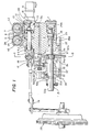
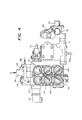
- Figs. 1 through 4 illustrate a hydraulic control unit according to the invention, in which are incorporated in one body a clutch operating mechanism 3 and a change gear operating mechanism 21.
- the hydraulic control unit 1 is mounted on top of a speed change gear 35.
- a clutch cylinder 4 forming part of the clutch operating mechanism 3 is incorporated in a housing 2 of the hydraulic control unit 1.
- a cylinder barrel 5 is fitted in an open end portion of the clutch cylinder 4, in which is slidably received a shaft 6. At one end of the shaft 6, a piston 9 is received within the clutch cylinder 4 for sliding movement therein relative to the shaft 6.
- An 0-ring 7 is fitted in the outer peripheral surface of the piston 9 in slidable contact with the inner peripheral surface of the cylinder 4, and another O-ring 8 in the inner peripheral surface of the same piston 9 in slidable contact with the outer peripheral surface of the shaft 6, respectively.
- a washer 10 larger in diameter than the one end of the shaft 6 is fastened to the same end of the shaft 6 by means of a nut 11 screwed thereon so that after the piston 9 rightwardly moves into contact with the washer 10 as viewed in Fig. 1, the shaft 6 is also rightwardly moved together with the piston 9.
- the other end portion of the cylinder 4 is closed by a cap 13 fitted therein in airtight manner via an 0-ring 12 interposed between the cylinder 4 and the cap 13.
- a hydrauiic oil chamber 4A and an air chamber 4B are defined within the closed cylinder 4 at opposite sides of the piston 9.
- the hydraulic oil chamber 4A is connected to solenoid type selector valves 41-43 (in Fig. 4) mounted on an upper surface of the housing 2, by way of oil passages formed within the housing 2.
- a potentiometer 15 Fixed to the cap 13 is a potentiometer 15 having a known construction as a clutch position sensor, which has a probe rod 16 projected into the air chamber 4B in axial alignment with the shaft 6.
- the probe rod 16 is biased in the leftward direction as viewed in Fig. 1 by the force of a spring, not shown, disposed within the potentiometer 15, with its tip kept in urging contact with an opposed end face of the shaft 6.
- the probe rod 16 moves in unison with the movement of the shaft 6 so that the potentiometer 15 produces an output voltage corresponding to the axial position of the shaft 6 or that of a clutch lever 17.
- the clutch lever 17 is coupled at one end to the other end of the shaft 6 projected outwardly from the housing 2, by means of a pin 18, and at the other end to a clutch 20 through a clutch release means 19.
- the change gear operating mechanism 21 has a select shaft 22 fitted through a bore 23 formed in-the housing 2 and extends parallel with the shaft 6.
- the select shaft is slidably movable along its axis and also rotatable about its own axis.
- the select shaft 22 further extends through an internal lever chamber 2a formed within the housing 2 and communicating with the interior of the speed change gear 35.
- an internal lever 24 is rotatably fitted on the select shaft 22 at a central location of the chamber, of which one end 24a is projected toward the speed change gear 35 (in the downward direction as viewed in Fig. 1) in engagement with a change gear mechanism 37 thereof through a lever 36 as shown in Fig. 2.
- One end 22a of the select shaft 22 is projected outwardly from the housing 2 and adapted to be coupled with a manually operating speed change lever, not shown.
- This speed change lever is coupled to the select shaft 22 when it is desired to manually operate the speed change gear.
- a select piston 26 is secured to the other end of the select shaft 22 and fitted within a cylinder 25 formed in the housing 2, to define hydraulic oil chambers 25A and 25B within the cylinder 25 at its opposite sides. As shown in Fig. 5, these hydraulic oil chambers 25A, 25B are connected, respectively, to solenoid type selector valves 44 and 45 (in Fig. 3) mounted on an upper surface of the housing 2, by way of oil passages formed within the housing 2, to be selectively supplied with hydraulic operating oil for gear selecting operation of the select shaft 22.
- the other end 24b of the internal lever 24 is coupled to a shift shaft 29 of a shift cylinder 28 disposed at right angles to the select shaft 22, by means of a driving block 27 so that the internal lever 24 is rotated by the shift cylinder 28 for gear shifting operation.
- the internal lever 24 is fitted on a reduced- diameter portion 22'b of a shaft 22' disposed at the other end of the select shaft 22.
- Two pins 31 are axially planted in the internal lever 24 and projected from an axial end face of the lever 24 in a manner axially overlapping with an axial surface of a notch 22"c formed in another shaft 22" as shown in Fig. 3 with a slight gap therebetween, so that when the select shaft 22 is rotated about its own axis through an angle larger than a predetermined angle by manually operating the manual speed change lever coupled to the one end 22a of the select shaft 22, the pins 31 are pressed against the axial surface of the notch 22"c to cause rotation of the internal lever 24 about the shaft 22'.
- selected gear position sensor elements 50-52 are arranged around the end portion 22a of the select shaft 22 (the shaft 22") at.circumferentially and axially different locations so as to sense the axial position of an annular groove 22d formed in the outer peripheral surface of the shaft 22" at a predetermined axial location, and the sensor generates an output signal indicative of the sensed position of the select shaft 22, that is, a selected gear position of the speed change gear 35.
- the sensor elements 50-52 are formed of on-off switches having a conventional construction, which are each turned on when tip of the probe 50a-52a stretches into the annular groove 22d in the select shaft 22, and turned off when the probe is retracted by contact with a land of the select shaft 22 adjacent the annular groove 22d.
- Shifted gear position sensor elements 53-55 are arranged around an end portion 29a of the shift shaft 29 at circumferentially and axially different locations to sense the axial position of an annular groove 29b formed in the outer peripheral surface of the shaft 29 at a predetermined axial location, and the sensor generates an output signal indicative of the sensed position of the shift shaft 29, that is, a shifted gear position of the speed change gear 35.
- the sensor elements 53-55 are formed of on-off switches having a conventional construction, which are each turned on when tip of the probe 53a-55a stretches into the annular groove 29b in the shift shaft 29, and turned off when the probe is retracted by contact with a land of the shift shaft 29 adjacent the annular groove 29b.
- a passage 2b is formed in the housing 2 as shown in Fig. 1, which extends horizontally in the housing 2 along its majority part at a location below the clutch cylinder 4, of which one end is upwardly directed to open in the bottom surface or lower peripheral surface of the air chamber 4B of the clutch cylinder 4, and the other end opens in the internal lever chamber 2a.
- An air breather 48 is fitted through an end of a passage 2c formed through a side wall of the housing 2 defining the internal lever chamber 2a, to communicate the internal lever chamber 2a with the atmosphere through the passage 2c and the air breather 48.
- the air chamber 4B of the clutch cylinder 4 communicates with the atmosphere through the passage 2b, the internal lever chamber 2a, the passage 2c, and the air breather 48.
- the air breather 48 provided on the side of the speed change gear 35 can also serve as an air breather for the air chamber 4B.
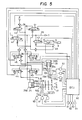
- the oil hydraulic circuit and electrical circuit of the hydraulic control unit 1 are shown in Fig. 5.
- the hydraulic oil chamber 4A of the clutch cylinder 4 is connected to the solenoid valve 40 through the solenoid valve 41, and also to a passage 2B leading to an oil tank T selectively through the solenoid valve 42 or 43.
- the hydraulic oil chambers 28A, 28B of the gear shifting cylinder 28 are each connected selectively to the solenoid valve 40 or to the passage 2B through a respective solenoid valve 46, 47.
- the hydraulic oil chambers 25A, 25B of the gear selecting cylinder 25 are each connected selectively to the solenoid valve 40 or to the passage 2B through the respective solenoid valve 44, 45.
- the solenoid valve 40 is connected to an oil hydraulic pump P through a passage 2A formed in the housing 2 as shown in Fig. 4.
- the passage 2B is formed in the housing 2.
- the clutch position sensor 15, the selected gear position sensor elements 50-52, and the shifted gear position sensor elements 53-55 are electrically connected to an electronic control unit (hereinafter called “the ECU") 60 to supply same with respective output signals.
- the ECU 60 Further electrically connected to the ECU 60 are various sensors for sensing operating conditions of the engine, for instance, an engine rotational speed sensor 61, a rotational speed sensor 62 for sensing the rotational speed of the input shaft of the speed change gear, an accelerator pedal position sensor 63, and an engine cooling water temperature sensor 64.
- the ECU 60 operates on output signals from the above sensors to control the operations of the aforesaid solenoid valves 40-47 for control of the clutch operating mechanism 3 and the change gear operating mechanism 21.
- the hydraulic actuators for gear selecting and shifting operations of the speed change gear are incorporated in the single housing 2 to provide a single-body hydraulic control unit, which makes it possible to minimize the number of connection pipes to be used in the oil hydraulic circuit, thus avoiding the complication of the piping, design the control unit compact in size, and improve the operational stability and efficiency of assemblage of the control unit.
- hydraulic operating oil which leaks from the hydraulic oil chamber 4A of the clutch cylinder 4 to the air chamber 4B thereof as the clutch operating mechanism 3 operates, can drain through the passage 2b formed in the housing 2 into the interior of the speed change gear 35 via the internal lever chamber 2a, without staying in the air chamber 4B, thus avoiding degradation of the performance of the potentiometer 15 as well as malfunction of the hydraulic actuator 3 for the clutch, particularly, the piston 9, which would be otherwise caused by the leakage of oil.
- the single air breather 48 for both the speed change gear 35 and the air chamber 4B can be prevented the intrusion of water, dust, etc. into the air chamber 4B from outside.
Landscapes
- Engineering & Computer Science (AREA)
- Mechanical Engineering (AREA)
- Transportation (AREA)
- General Engineering & Computer Science (AREA)
- Chemical & Material Sciences (AREA)
- Combustion & Propulsion (AREA)
- Automation & Control Theory (AREA)
- Physics & Mathematics (AREA)
- Fluid Mechanics (AREA)
- Gear-Shifting Mechanisms (AREA)
- General Details Of Gearings (AREA)
- Hydraulic Clutches, Magnetic Clutches, Fluid Clutches, And Fluid Joints (AREA)
Claims (6)
Applications Claiming Priority (4)
| Application Number | Priority Date | Filing Date | Title |
|---|---|---|---|
| JP12807883U JPS6034928U (ja) | 1983-08-19 | 1983-08-19 | 車輛用変速装置の油圧制御ユニット |
| JP128077/83 | 1983-08-19 | ||
| JP128078/83 | 1983-08-19 | ||
| JP1983128077U JPS6035951U (ja) | 1983-08-19 | 1983-08-19 | 自動変速装置 |
Publications (3)
| Publication Number | Publication Date |
|---|---|
| EP0142221A2 EP0142221A2 (de) | 1985-05-22 |
| EP0142221A3 EP0142221A3 (en) | 1986-05-07 |
| EP0142221B1 true EP0142221B1 (de) | 1988-12-28 |
Family
ID=26463852
Family Applications (1)
| Application Number | Title | Priority Date | Filing Date |
|---|---|---|---|
| EP84305552A Expired EP0142221B1 (de) | 1983-08-19 | 1984-08-15 | Hydraulische Steuereinheit für Fahrzeuggetriebe |
Country Status (3)
| Country | Link |
|---|---|
| US (1) | US4625840A (de) |
| EP (1) | EP0142221B1 (de) |
| DE (1) | DE3475762D1 (de) |
Cited By (2)
| Publication number | Priority date | Publication date | Assignee | Title |
|---|---|---|---|---|
| FR2872101A1 (fr) * | 2004-06-25 | 2005-12-30 | Thierry Carniel | Dispositif de commande automatique de manoeuvres d'une boite de vitesses manuelle d'un vehicule automobile |
| WO2025008151A1 (de) * | 2023-07-05 | 2025-01-09 | Knorr-Bremse Systeme für Nutzfahrzeuge GmbH | Fahrzeuggetriebe und ein verfahren zum steuern von getriebestellern in einem fahrzeuggetriebe |
Families Citing this family (29)
| Publication number | Priority date | Publication date | Assignee | Title |
|---|---|---|---|---|
| JPS63303247A (ja) * | 1987-05-30 | 1988-12-09 | Diesel Kiki Co Ltd | 自動変速装置 |
| DE3820874A1 (de) * | 1987-06-27 | 1989-01-05 | Zahnradfabrik Friedrichshafen | Kupplungseinrichtung |
| GB8725981D0 (en) * | 1987-11-05 | 1987-12-09 | Eaton Corp | X-y shifting mechanism |
| US4856628A (en) * | 1987-11-17 | 1989-08-15 | Hino Jidosha Kogyo Kabushiki Kaisha | Automated mechanical transmission system for use in commercial vehicles |
| HUT51548A (en) * | 1988-07-15 | 1990-05-28 | Attila Madocsay | Device for automatic switching the multi-stage mechanic gear box of motor vehicles |
| EP0378218B1 (de) * | 1989-01-13 | 1995-05-10 | IVECO FIAT S.p.A. | Kraftfahrzeug-Antriebssteuerungssystem |
| FR2643316B1 (fr) * | 1989-02-17 | 1993-09-10 | Valeo | Dispositif de detection de vitesse pour la commande d'un embrayage associe a une boite de vitesses |
| US5167311A (en) * | 1989-09-26 | 1992-12-01 | Zexel Corporation | Transmission control system with gear shift failure detection |
| IT1251250B (it) * | 1991-11-08 | 1995-05-05 | Iveco Fiat | Cambio di velocita' per un veicolo industriale provvisto di un'unita' di comando integrata. |
| GB9314951D0 (en) * | 1993-07-17 | 1993-09-01 | Prodrive Eng Ltd | Gear change mechanism |
| GB9502140D0 (en) * | 1995-02-03 | 1995-03-22 | Automotive Products Plc | Clutch and transmission ratio control |
| WO1997002963A2 (de) * | 1995-07-12 | 1997-01-30 | Luk Getriebe-Systeme Gmbh | Kupplungs- und getriebebetätigungsvorrichtung |
| BR9606640A (pt) * | 1995-09-12 | 1997-09-30 | Luk Getriebe Systeme Gmbh | Veículo automotor com um equipamento para o acionamento do sistema de transmissão de momento de rotação e da caixa de mudança |
| US5928106A (en) * | 1997-10-16 | 1999-07-27 | Navistar International Transportation Corp | Electro-hydraulic clutch actuation system for manual transmission |
| IT1310211B1 (it) | 1999-04-14 | 2002-02-11 | Digitek Srl | Servocomando automatico per cambio sequenziale e frizione. |
| AU2845901A (en) * | 2000-01-10 | 2001-07-24 | Ise Industries Gmbh | Manual gearbox for a passenger motor vehicle |
| FR2807718B1 (fr) * | 2000-04-18 | 2002-07-19 | Renault | Dispositif de commande d'une boite de vitesses |
| GB2368886A (en) * | 2000-11-13 | 2002-05-15 | Luk Lamellen & Kupplungsbau | Automatic transmission with a hydraulic actuation system |
| DE10103843A1 (de) * | 2001-01-30 | 2002-08-01 | Zf Sachs Ag | Auf hydraulischem Wege betätigbares Kupplungssystem |
| DE10360611A1 (de) * | 2003-12-19 | 2005-07-21 | Fte Automotive Gmbh & Co. Kg | Hydraulischer Funktionsblock |
| DE102005015485A1 (de) | 2005-04-05 | 2006-11-30 | Daimlerchrysler Ag | Antriebsstrang eines Fahrzeuges und Verfahren zur Steuerung eines Antriebsstranges |
| DE102005015481A1 (de) * | 2005-04-05 | 2006-10-19 | Daimlerchrysler Ag | Schalteinrichtung eines automatisierten Getriebes eines Kraftfahrzeugs |
| DE102005015482A1 (de) * | 2005-04-05 | 2006-10-19 | Daimlerchrysler Ag | Schaltmodul eines automatisierten Getriebes eines Kraftfahrzeugs |
| DE102005021760A1 (de) * | 2005-05-11 | 2006-11-16 | Zf Friedrichshafen Ag | Mehrgruppengetriebe |
| DE102005021761A1 (de) * | 2005-05-11 | 2006-11-30 | Zf Friedrichshafen Ag | Mehrgruppengetriebe |
| DE102005028122A1 (de) * | 2005-06-10 | 2006-12-14 | Getrag Getriebe- Und Zahnradfabrik Hermann Hagenmeyer Gmbh & Cie Kg | Automatisiertes Vorgelegegetriebe und Verfahren zu dessen Herstellung |
| CN101046250B (zh) * | 2006-03-31 | 2010-05-12 | 上海盈达信汽车电子有限公司 | 一种电控液动自动变速作动器 |
| DE102010029861A1 (de) * | 2010-06-09 | 2011-12-15 | Zf Friedrichshafen Ag | Fahrzeuggetriebe |
| EP4083474B1 (de) * | 2021-04-26 | 2024-02-28 | Volvo Truck Corporation | Verfahren zur steuerung der belüftung eines getriebes |
Family Cites Families (7)
| Publication number | Priority date | Publication date | Assignee | Title |
|---|---|---|---|---|
| US2664980A (en) * | 1951-02-14 | 1954-01-05 | Austin Motor Co Ltd | Clutch and gear change operating system for automobiles |
| US2992565A (en) * | 1958-03-10 | 1961-07-18 | Kearney & Trecker Corp | Automatic speed change mechanism |
| FR1247819A (fr) * | 1959-03-26 | 1960-10-24 | Magneti Marelli Spa | Appareil de servocommande pneumatique pour débrayer l'embrayage avec soupape de contrôle du changement de vitesse, en particulier pour véhicules |
| GB1099404A (en) * | 1964-04-15 | 1968-01-17 | Turner Mfg Co Ltd | Improvements in and relating to gear shift mechanisms |
| US3478851A (en) * | 1967-08-09 | 1969-11-18 | Smyth Robert Ralston | Automotive transmission |
| FR2078997A5 (de) * | 1970-02-28 | 1971-11-05 | Cav Ltd | |
| WO1981003000A1 (en) * | 1980-04-14 | 1981-10-29 | K Bostroem | A gear shifting device |
-
1984
- 1984-08-13 US US06/640,316 patent/US4625840A/en not_active Expired - Fee Related
- 1984-08-15 EP EP84305552A patent/EP0142221B1/de not_active Expired
- 1984-08-15 DE DE8484305552T patent/DE3475762D1/de not_active Expired
Cited By (2)
| Publication number | Priority date | Publication date | Assignee | Title |
|---|---|---|---|---|
| FR2872101A1 (fr) * | 2004-06-25 | 2005-12-30 | Thierry Carniel | Dispositif de commande automatique de manoeuvres d'une boite de vitesses manuelle d'un vehicule automobile |
| WO2025008151A1 (de) * | 2023-07-05 | 2025-01-09 | Knorr-Bremse Systeme für Nutzfahrzeuge GmbH | Fahrzeuggetriebe und ein verfahren zum steuern von getriebestellern in einem fahrzeuggetriebe |
Also Published As
| Publication number | Publication date |
|---|---|
| DE3475762D1 (en) | 1989-02-02 |
| EP0142221A3 (en) | 1986-05-07 |
| EP0142221A2 (de) | 1985-05-22 |
| US4625840A (en) | 1986-12-02 |
Similar Documents
| Publication | Publication Date | Title |
|---|---|---|
| US4625840A (en) | Hydraulic control unit for automotive transmissions | |
| US3939722A (en) | Arrangement for controlling gear changes in a motor vehicle gear box | |
| US8635925B2 (en) | Transmission auxiliary unit shift inhibitor | |
| KR100334736B1 (ko) | 전기모터액츄에이터와가압유체오버라이드를가지는차량자동클러치용액츄에이터시스템 | |
| US5992590A (en) | Hydraulic actuation system | |
| US5038627A (en) | Vehicle transmission with manually shifted lower gears and automatically shifted upper gears | |
| US5473959A (en) | Transmission shifting apparatus having manually operable selector shaft | |
| US4287784A (en) | Apparatus for facilitating gear changing in mechanical gearboxes | |
| US4432431A (en) | Change speed multiple axle shift lock out | |
| JP2004503730A (ja) | 車両変速機の電空式切換装置 | |
| GB2214248A (en) | Ratio selector system using fluid actuators and ectrohydraulic control in a vehicle transmission | |
| US4516669A (en) | Gear shifting device | |
| US3470759A (en) | Power-assisted change-speed devices | |
| US6880419B2 (en) | Internal electronic transmission range selection (ETRS) system for an automatic transmission | |
| US3766793A (en) | Transmission shift controls | |
| US2753024A (en) | Hydraulically operated clutch and gear change mechanisms for automobiles | |
| GB2089450A (en) | Gearshift protection device | |
| US5067362A (en) | Control device | |
| GB2057607A (en) | Arrangement for Blocking a Vehicle Clutch | |
| US6006621A (en) | Automatic speed-change apparatus for a gear transmission | |
| US5797294A (en) | Shift valve | |
| US4559895A (en) | Positioning device | |
| US3748929A (en) | Variable power train and control | |
| KR100200100B1 (ko) | 전기 공압 작동식 변속장치의 피스톤 센서장치 | |
| GB2064029A (en) | Valve for interlocked control of range gear |
Legal Events
| Date | Code | Title | Description |
|---|---|---|---|
| PUAI | Public reference made under article 153(3) epc to a published international application that has entered the european phase |
Free format text: ORIGINAL CODE: 0009012 |
|
| 17P | Request for examination filed |
Effective date: 19841224 |
|
| AK | Designated contracting states |
Designated state(s): CH DE FR GB IT LI SE |
|
| PUAL | Search report despatched |
Free format text: ORIGINAL CODE: 0009013 |
|
| AK | Designated contracting states |
Kind code of ref document: A3 Designated state(s): CH DE FR GB IT LI SE |
|
| 17Q | First examination report despatched |
Effective date: 19870813 |
|
| GRAA | (expected) grant |
Free format text: ORIGINAL CODE: 0009210 |
|
| AK | Designated contracting states |
Kind code of ref document: B1 Designated state(s): CH DE FR GB IT LI SE |
|
| REF | Corresponds to: |
Ref document number: 3475762 Country of ref document: DE Date of ref document: 19890202 |
|
| ET | Fr: translation filed | ||
| ITF | It: translation for a ep patent filed | ||
| PLBE | No opposition filed within time limit |
Free format text: ORIGINAL CODE: 0009261 |
|
| STAA | Information on the status of an ep patent application or granted ep patent |
Free format text: STATUS: NO OPPOSITION FILED WITHIN TIME LIMIT |
|
| 26N | No opposition filed | ||
| REG | Reference to a national code |
Ref country code: CH Ref legal event code: PFA Free format text: ZEXEL CORPORATION |
|
| ITPR | It: changes in ownership of a european patent |
Owner name: TRASFORMAZIONE SOCIETARIA;ZEXEL CORPORATION |
|
| ITTA | It: last paid annual fee | ||
| PGFP | Annual fee paid to national office [announced via postgrant information from national office to epo] |
Ref country code: GB Payment date: 19920804 Year of fee payment: 9 |
|
| PGFP | Annual fee paid to national office [announced via postgrant information from national office to epo] |
Ref country code: FR Payment date: 19920807 Year of fee payment: 9 |
|
| PGFP | Annual fee paid to national office [announced via postgrant information from national office to epo] |
Ref country code: CH Payment date: 19920814 Year of fee payment: 9 |
|
| PGFP | Annual fee paid to national office [announced via postgrant information from national office to epo] |
Ref country code: SE Payment date: 19920817 Year of fee payment: 9 |
|
| PGFP | Annual fee paid to national office [announced via postgrant information from national office to epo] |
Ref country code: DE Payment date: 19920824 Year of fee payment: 9 |
|
| PG25 | Lapsed in a contracting state [announced via postgrant information from national office to epo] |
Ref country code: GB Effective date: 19930815 |
|
| PG25 | Lapsed in a contracting state [announced via postgrant information from national office to epo] |
Ref country code: SE Effective date: 19930816 |
|
| PG25 | Lapsed in a contracting state [announced via postgrant information from national office to epo] |
Ref country code: LI Effective date: 19930831 Ref country code: CH Effective date: 19930831 |
|
| GBPC | Gb: european patent ceased through non-payment of renewal fee |
Effective date: 19930815 |
|
| PG25 | Lapsed in a contracting state [announced via postgrant information from national office to epo] |
Ref country code: FR Effective date: 19940429 |
|
| REG | Reference to a national code |
Ref country code: CH Ref legal event code: PL |
|
| PG25 | Lapsed in a contracting state [announced via postgrant information from national office to epo] |
Ref country code: DE Effective date: 19940503 |
|
| REG | Reference to a national code |
Ref country code: FR Ref legal event code: ST |
|
| EUG | Se: european patent has lapsed |
Ref document number: 84305552.6 Effective date: 19940310 |