EP0142400A1 - Gehäuse für eine elektronische Komponente, insbesondere bestimmt für Telephonschutz - Google Patents
Gehäuse für eine elektronische Komponente, insbesondere bestimmt für Telephonschutz Download PDFInfo
- Publication number
- EP0142400A1 EP0142400A1 EP84401912A EP84401912A EP0142400A1 EP 0142400 A1 EP0142400 A1 EP 0142400A1 EP 84401912 A EP84401912 A EP 84401912A EP 84401912 A EP84401912 A EP 84401912A EP 0142400 A1 EP0142400 A1 EP 0142400A1
- Authority
- EP
- European Patent Office
- Prior art keywords
- housing
- contact
- contacts
- electronic component
- base
- Prior art date
- Legal status (The legal status is an assumption and is not a legal conclusion. Google has not performed a legal analysis and makes no representation as to the accuracy of the status listed.)
- Granted
Links
Images

Classifications
-
- H—ELECTRICITY
- H05—ELECTRIC TECHNIQUES NOT OTHERWISE PROVIDED FOR
- H05K—PRINTED CIRCUITS; CASINGS OR CONSTRUCTIONAL DETAILS OF ELECTRIC APPARATUS; MANUFACTURE OF ASSEMBLAGES OF ELECTRICAL COMPONENTS
- H05K7/00—Constructional details common to different types of electric apparatus
- H05K7/20—Modifications to facilitate cooling, ventilating, or heating
- H05K7/2039—Modifications to facilitate cooling, ventilating, or heating characterised by the heat transfer by conduction from the heat generating element to a dissipating body
- H05K7/20436—Inner thermal coupling elements in heat dissipating housings, e.g. protrusions or depressions integrally formed in the housing
- H05K7/2049—Pressing means used to urge contact, e.g. springs
-
- H—ELECTRICITY
- H01—ELECTRIC ELEMENTS
- H01C—RESISTORS
- H01C1/00—Details
- H01C1/08—Cooling, heating or ventilating arrangements
- H01C1/084—Cooling, heating or ventilating arrangements using self-cooling, e.g. fins, heat sinks
Definitions
- the present invention relates to a housing for an electronic component comprising two opposite planar faces coated with electrodes, said housing comprising a cover and a base crossed by at least first and second electrical contacts, the end of said contacts located in the housing being intended to be connected respectively to an electrode of the component.
- Telephone lines are the site of intense electrical disturbances due to atmospheric discharges as well as direct or induced galvanic connections with an electrical energy distribution line. It therefore proved necessary to protect them both against overvoltages and overcurrents which could lead to the destruction of the subscriber's central office or telephone handset.
- French patent 2,494,925 describes a component for telephone protection essentially consisting of a resistance with a positive temperature coefficient and a thermally coupled varistor. Besides the fact that such a component has a large parasitic capacity due to the production by two adjoining discs, no solution is given in this patent as to the connection of the elements to one another, their arrangement in a housing, in particular for obtain a component which inside its casing has low bulk characteristics, taking into account the constraints imposed by the manufacturers of telephone equipment.
- the housing according to the invention makes it possible to solve the various problems posed above.
- said electrical contact has one end external to the housing ensuring thermal dissipation by convection of calories by the component, the other part of the electrical contacts ensuring thermal conduction of said calories to said lower end .
- the two contacts arranged vertically, pass through the base substantially at 90 ° relative to each other, the first contact intended for contact with the lower electrode of the component comprising an H-shaped part, the two arms lower parts of the H constituting the connection tabs of the contact, said first contact further comprising in its middle a substantially horizontal part coming to bear on the bottom of the base of the housing, while the second contact intended for contact with the electrode of the component is an elastic contact provided with several fingers.
- the bottom of the base has an opening allowing the dissipation of calories by the reverse side of the horizontal part of the first contact, said base being able to be made of a material the softening temperature of which is lower than the maximum operating temperature of the component.
- the shape of this horizontal part of the second contact corresponds to the housing produced in the base and allows said contact to be held in a horizontal plane.
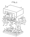
- Figure 1 an exploded view of a first embodiment of a housing according to the invention.
- This box comprises a base 8, a cover 9 and four electrical contacts 4 and 5, 6 and 7.
- the contacts 4 and 5 are intended for the connection of component 1 in the characteristic is to have two opposite planar faces provided with electrodes (not shown in the figure).
- this component 1 has the shape of a disc.
- the first contact 4 comprises a vertical H-shaped part and a horizontal part connected to the previous one between the two upper arms of the H. This contact has the particularity of being cut from a single piece and then folded at 90 °.
- the vertical part comprises, on its lower portion, the two lower arms of the H, 20 and 21 intended for the electrical connection on the printed circuit.
- a substantially rectangular contact body 70 comprising an elastic cutout 22 intended to maintain contact in a vertical plane after passing through the opening 34 of the base 8.
- the upper part thereof is located at a height D 3 from the base of the two lower arms of the H, this height D 3 determining the heat dissipation surface outside the housing of said contact 4.
- the two upper arms 23 and 24 of the vertical H-shaped part have two edges on their outer portions 45 and 46 abutting against the base 8.
- the horizontal part of the contact 4 is connected to the vertical part by the portion 25 of width and height corresponding exactly to the space 31 located between the two branches 23 and 24. It extended by a part 26 coming into electrical and thermal contact with the lower electrode of the component 1.
- This part 26 is externally limited by the portions 27, 28, 29 and 30 delimiting a diameter substantially equal to that of the internal groove 17 of the 'base 8, this in order to limit the horizontal displacement of the contact once it is fixed in the base 8.
- the second contact 5 whose lower part is identical to the lower part of the H-shaped vertical part of the first contact, so it has two connection tabs 71, 72, a body 73 intended for heat dissipation outside the base 8, an identical elastic holding device 74 at 22, so q eu on its upper part two flanges 47 (only one is shown in the figure) coming to bear on the base 8 after insertion of the contact 5 in the slot 37 of said base 8.
- the upper part of this second contact 5 comprises a first rectangular fold 75 substantially at 90 ° to the body of the contact 5, said rectangular portion extending by a plurality of elastic fingers 16 (four fingers are shown in the figure). These fingers are inclined in the example shown here substantially at approximately 30 ° relative to the horizontal. Each elastic finger is independent of the neighboring finger and its inclination and the length of each of the fingers is such that in the absence of component 1 intended to be electrically and thermally connected between the two contacts 4 and 5, there is no electrical contact between the first contact 4 and the second contact 5. This is a characteristic of the invention, allowing in the event of spraying due to an overvoltage or overcurrent of the component 1 to allow the assembly to behave like a switch open.
- the component housing according to the invention also comprises in the present case (but this is not essential, only the first and second contacts being) a third and a fourth contacts respectively 6 and 7 of identical shape.
- These contacts have a shape substantially identical to the vertical part of the first contact 4, namely two connection tabs 40, 41, 42, 43, a body 76, 77 whose lower part of height D 3 allows heat dissipation to outside the housing, and comprising an elastic fixing means 39, 44, making it possible to maintain the contact in a vertical position, after passage of the latter in the corresponding slot 36, 35 of the base 8.
- the upper part of these contacts comprises shoulders 50, 51, 48, 49, said shoulders also abutting against the walls of the base adjacent to the slots 36 and 35.
- These elements 2 and 3 can be either semi elements conductors (of the diode, thyristor, etc.), or passive elements such as varistors, resistors, etc.
- the height contact portion D 3 which has a heat dissipation function for the calories generated by the component 1 also has a second washing foot function facilitating the washing of the printed circuit after soldering the housing with these components on said circuit.
- the housing according to the invention allows thermal coupling between the components such as 1 and the components such as 2 and 3, taking into account the fact that these are always arranged substantially at the same distance from one of the 'other.
- a washer of thermal insulation such as an asbestos sheet, for example
- the contact elements 4, 5, 6, 7 will be made of metals such as beryllium bronze, stainless steel, etc. so as to ensure good electrical conductivity at the same time as elastic power.
- they are chosen to be thin (preferably from 1 to 4/10 mm, so as not to exhibit significant thermal inertia, which could slow the switching times of the circuit using them.
- the width of these contacts (substantially identical to the width of the slots such as 35, 36, 37, 34) will be large so that said contacts have large surfaces for electrical contact with the various components and to ensure good heat dissipation of the calories generated by the component 1, in particular in their parts of height D 1 , D 2 and D3.
- connection tabs 20 and 21 makes it possible on the one hand to strengthen the quality of fixing of the printed circuit and on the other hand to reduce the current density in the event of overload.
- the lower contact 4, in particular in its horizontal part 26, can be made of metal of the type known under the name "expanded metal", making it possible to increase the number of contact points due to the relief of it.
- a mark 19 placed on the cover 9 of the housing allows the external location of said housing in the case of automatic insertion using an adequate machine.
- Figure 2 shows a second embodiment of a housing according to the invention, housing in which are arranged two sets of contacts for component in the form of a disc such as a resistor with positive temperature coefficient PTC.
- the base 8 and the housing 9 are here of rectangular shape taking into account the presence of two sets of first and second contacts 4 and 5, arranged side by side.
- the contacts 4 and 5 of each assembly are identical in all respects to those described in the previous figure, as are the cells 17 located in the base 8, said cells 17 having, again, a keyhole-like shape as in the previous figure, with the opening 32 opening onto the underside of the base.
- a third contact 106 has been arranged with a shape different from that of the third and fourth contacts of the previous figure.
- the contact 106 simply comprises two connection tabs 112, 113, interconnected inside the housing by a flat portion 114 on which are arranged two arms 115 and 116 substantially perpendicular and upward. These two arms are intended for the connection of components such as 2 and 3 as envisaged in the description of FIG. 1.
- this contact 106 is not necessary if one wishes to use only one or two disc type components with electrodes.
Landscapes
- Engineering & Computer Science (AREA)
- Microelectronics & Electronic Packaging (AREA)
- Physics & Mathematics (AREA)
- Thermal Sciences (AREA)
- Coupling Device And Connection With Printed Circuit (AREA)
- Connector Housings Or Holding Contact Members (AREA)
- Thermistors And Varistors (AREA)
Applications Claiming Priority (2)
| Application Number | Priority Date | Filing Date | Title |
|---|---|---|---|
| FR8315337 | 1983-09-27 | ||
| FR8315337A FR2552585B1 (fr) | 1983-09-27 | 1983-09-27 | Boitier pour composant electronique destine notamment a la protection telephonique |
Publications (2)
| Publication Number | Publication Date |
|---|---|
| EP0142400A1 true EP0142400A1 (de) | 1985-05-22 |
| EP0142400B1 EP0142400B1 (de) | 1987-11-11 |
Family
ID=9292575
Family Applications (1)
| Application Number | Title | Priority Date | Filing Date |
|---|---|---|---|
| EP84401912A Expired EP0142400B1 (de) | 1983-09-27 | 1984-09-26 | Gehäuse für eine elektronische Komponente, insbesondere bestimmt für Telephonschutz |
Country Status (3)
| Country | Link |
|---|---|
| EP (1) | EP0142400B1 (de) |
| DE (1) | DE3467492D1 (de) |
| FR (1) | FR2552585B1 (de) |
Cited By (2)
| Publication number | Priority date | Publication date | Assignee | Title |
|---|---|---|---|---|
| GB2316235A (en) * | 1996-08-09 | 1998-02-18 | Motorola Israel Ltd | Heat sink and grounding arrangement |
| WO2006099831A1 (de) * | 2005-03-24 | 2006-09-28 | Conti Temic Microelectronic Gmbh | Anordnung zur wärmeableitung |
Citations (3)
| Publication number | Priority date | Publication date | Assignee | Title |
|---|---|---|---|---|
| US3988709A (en) * | 1975-05-12 | 1976-10-26 | Eugene T. McKinnon | Electric motor controlling relay |
| US3996447A (en) * | 1974-11-29 | 1976-12-07 | Texas Instruments Incorporated | PTC resistance heater |
| GB2019653A (en) * | 1978-04-24 | 1979-10-31 | Cts Corp | Variable resistors |
-
1983
- 1983-09-27 FR FR8315337A patent/FR2552585B1/fr not_active Expired
-
1984
- 1984-09-26 EP EP84401912A patent/EP0142400B1/de not_active Expired
- 1984-09-26 DE DE8484401912T patent/DE3467492D1/de not_active Expired
Patent Citations (3)
| Publication number | Priority date | Publication date | Assignee | Title |
|---|---|---|---|---|
| US3996447A (en) * | 1974-11-29 | 1976-12-07 | Texas Instruments Incorporated | PTC resistance heater |
| US3988709A (en) * | 1975-05-12 | 1976-10-26 | Eugene T. McKinnon | Electric motor controlling relay |
| GB2019653A (en) * | 1978-04-24 | 1979-10-31 | Cts Corp | Variable resistors |
Cited By (2)
| Publication number | Priority date | Publication date | Assignee | Title |
|---|---|---|---|---|
| GB2316235A (en) * | 1996-08-09 | 1998-02-18 | Motorola Israel Ltd | Heat sink and grounding arrangement |
| WO2006099831A1 (de) * | 2005-03-24 | 2006-09-28 | Conti Temic Microelectronic Gmbh | Anordnung zur wärmeableitung |
Also Published As
| Publication number | Publication date |
|---|---|
| DE3467492D1 (en) | 1987-12-17 |
| EP0142400B1 (de) | 1987-11-11 |
| FR2552585B1 (fr) | 1985-11-08 |
| FR2552585A1 (fr) | 1985-03-29 |
Similar Documents
| Publication | Publication Date | Title |
|---|---|---|
| EP0683547A1 (de) | Verbindungsvorrichtung zur Sicherstellung der Verbindung zwischen einen coaxial Kabel und eine gedrückte Schaltung und gedrückte Schaltung mit solchen ausgestatte Vorrichtung | |
| FR2551916A1 (fr) | Terminaison d'un element de coupe-circuit pour un coupe-circuit de limitation du courant | |
| EP0625284A1 (de) | Flachsicherung für hohe nennströme | |
| EP3712908B1 (de) | Schutzvorrichtung gegen überspannungen | |
| EP0621733A1 (de) | Steckbarer Schutzmodul für Module für schnelle Verbindung von Fernsprechleitungen | |
| FR2725304A1 (fr) | Fusible pour microplaquette | |
| EP0308306A1 (de) | PTC-Thermistor für Oberflächenbestückung | |
| EP0142400B1 (de) | Gehäuse für eine elektronische Komponente, insbesondere bestimmt für Telephonschutz | |
| FR2875672A1 (fr) | Dispositif electronique avec repartiteur de chaleur integre | |
| KR100318397B1 (ko) | Ntc서미스터 | |
| EP1912261A1 (de) | Elektrische Anschlussvorrichtung, insbesondere für elektrischen Sonnenkollektor | |
| EP2536261A1 (de) | Elektronisches Leistungsmodul mit integierter Kapazität | |
| FR2810154A1 (fr) | Module de condensateur d'onduleur et onduleur | |
| EP1830369B1 (de) | Vorrichtung zum Schutz gegen Überspannungen mit vereinfachtem Aufbau und verbesserter Zuverlässigkeit | |
| FR2569047A1 (fr) | Porte-fusible antichoc | |
| EP0680248B1 (de) | Verfahren zur Herstellung einer elektronischen Leistungsschaltung und nach diesem Verfahren erhaltene elektronische Schaltung | |
| WO2024083577A1 (fr) | Connecteur pour la fixation d'un câble sur un circuit imprimé | |
| EP4262323A1 (de) | Kochfeld und verfahren zum zusammenbau des kochfelds | |
| FR2669144A1 (fr) | Assemblage d'un bilame pour appareil de coupure de courant et d'une piece servant de support au bilame. | |
| FR2677178A1 (fr) | Connecteur. | |
| FR3159873A1 (fr) | Dispositif comportant une carte électronique et un condensateur connecté à la carte électronique | |
| FR2544516A1 (fr) | Plaque chauffante pour machine reprographique | |
| FR2758420A1 (fr) | Dispositif de protection a base de varistance | |
| FR2743686A1 (fr) | Composant electrique comportant des fils de raccordement en forme de pieds | |
| EP0119134A1 (de) | Zusammenbau-Anordnung für elektronische Leistungsbauelemente auf einem Kühlkörper und Anwendung für Monophasen- oder Polyphasen-Brücken |
Legal Events
| Date | Code | Title | Description |
|---|---|---|---|
| PUAI | Public reference made under article 153(3) epc to a published international application that has entered the european phase |
Free format text: ORIGINAL CODE: 0009012 |
|
| AK | Designated contracting states |
Designated state(s): DE GB IT NL |
|
| 17P | Request for examination filed |
Effective date: 19850727 |
|
| RAP1 | Party data changed (applicant data changed or rights of an application transferred) |
Owner name: COMPAGNIE EUROPEENNE DE COMPOSANTS ELECTRONIQUES L |
|
| 17Q | First examination report despatched |
Effective date: 19861223 |
|
| GRAA | (expected) grant |
Free format text: ORIGINAL CODE: 0009210 |
|
| AK | Designated contracting states |
Kind code of ref document: B1 Designated state(s): DE GB IT NL |
|
| ITF | It: translation for a ep patent filed | ||
| REF | Corresponds to: |
Ref document number: 3467492 Country of ref document: DE Date of ref document: 19871217 |
|
| GBT | Gb: translation of ep patent filed (gb section 77(6)(a)/1977) | ||
| PLBE | No opposition filed within time limit |
Free format text: ORIGINAL CODE: 0009261 |
|
| STAA | Information on the status of an ep patent application or granted ep patent |
Free format text: STATUS: NO OPPOSITION FILED WITHIN TIME LIMIT |
|
| 26N | No opposition filed | ||
| PG25 | Lapsed in a contracting state [announced via postgrant information from national office to epo] |
Ref country code: GB Effective date: 19890926 |
|
| PG25 | Lapsed in a contracting state [announced via postgrant information from national office to epo] |
Ref country code: NL Effective date: 19900401 |
|
| NLV4 | Nl: lapsed or anulled due to non-payment of the annual fee | ||
| GBPC | Gb: european patent ceased through non-payment of renewal fee | ||
| PG25 | Lapsed in a contracting state [announced via postgrant information from national office to epo] |
Ref country code: DE Effective date: 19900601 |