EP0142446B1 - Entwicklungsvorrichtung von latenten magnetischen Abbildungen - Google Patents
Entwicklungsvorrichtung von latenten magnetischen Abbildungen Download PDFInfo
- Publication number
- EP0142446B1 EP0142446B1 EP84402286A EP84402286A EP0142446B1 EP 0142446 B1 EP0142446 B1 EP 0142446B1 EP 84402286 A EP84402286 A EP 84402286A EP 84402286 A EP84402286 A EP 84402286A EP 0142446 B1 EP0142446 B1 EP 0142446B1
- Authority
- EP
- European Patent Office
- Prior art keywords
- magnetic
- magnetised
- recording surface
- developing latent
- particles
- Prior art date
- Legal status (The legal status is an assumption and is not a legal conclusion. Google has not performed a legal analysis and makes no representation as to the accuracy of the status listed.)
- Expired
Links
Images


Classifications
-
- G—PHYSICS
- G03—PHOTOGRAPHY; CINEMATOGRAPHY; ANALOGOUS TECHNIQUES USING WAVES OTHER THAN OPTICAL WAVES; ELECTROGRAPHY; HOLOGRAPHY
- G03G—ELECTROGRAPHY; ELECTROPHOTOGRAPHY; MAGNETOGRAPHY
- G03G19/00—Processes using magnetic patterns; Apparatus therefor, i.e. magnetography
-
- G—PHYSICS
- G03—PHOTOGRAPHY; CINEMATOGRAPHY; ANALOGOUS TECHNIQUES USING WAVES OTHER THAN OPTICAL WAVES; ELECTROGRAPHY; HOLOGRAPHY
- G03G—ELECTROGRAPHY; ELECTROPHOTOGRAPHY; MAGNETOGRAPHY
- G03G15/00—Apparatus for electrographic processes using a charge pattern
- G03G15/06—Apparatus for electrographic processes using a charge pattern for developing
- G03G15/08—Apparatus for electrographic processes using a charge pattern for developing using a solid developer, e.g. powder developer
- G03G15/095—Removing excess solid developer, e.g. fog preventing
Definitions
- the present invention relates to an apparatus for developing latent magnetic images and, more particularly to a retouching device which, in this apparatus, is intended to remove the excess developer particles which have been deposited on the recording surface. magnetic of this device.
- a touch-up device of this kind finds its application in particular in magnetic printing machines.
- non-impact printing machines In modern equipment used for information processing, more and more rapid printers are used in which the printing of the characters is carried out without for that calling upon the impact of types of relief printing on a sheet. of receiving paper.
- These so-called non-impact printing machines generally comprise a recording medium which, most often consisting of a rotary drum or an endless belt, is provided with a recording surface on which it is possible to form, electrostatically or magnetic, sensitized areas corresponding to the characters to be printed, these areas being capable of attracting solid particles of a powdery developer product.
- This drawback can be eliminated by using the retouching device which has been described in FR-A-2.322. 393 and which makes it possible to remove the excess developer particles which are on an endless magnetic strip on which a latent magnetic image has been formed.
- This retouching device comprises a guide roller with radius R, over which the endless magnetic strip passes. When this strip is driven at a constant speed V, the developer particles which are on this strip are subjected, during their passage in front of this guide roller, to the action of a centrifugal force whose value, on each particle of mass M, is equal to MV 2 / R.
- the endless magnetic strip must be driven at a speed at least equal to one meter per second.
- a speed of movement of this order does not allow this retouching device to be used in current magnetic printing machines in which the drive speed of the recording medium does not practically exceed 30 cm / s. So that this retouching device can be applied to such a printing machine, the diameter of the guide roller should indeed be reduced, but this solution would lead to choosing a guide roller whose diameter should not exceed two millimeters. A guide roller of this size would then necessarily be fragile and its use, in a magnetic printing machine, would not offer all the desired security.
- the present invention overcomes the drawbacks of the prior art and proposes an apparatus for developing latent magnetic images which comprises a retouching device capable of safely and homogeneously removing the excess developer particles on the support of recording of this device, even when this recording medium is driven at a speed of the order of a few tens of centimeters per second.
- the printing machine which has been shown diagrammatically in FIG. 1 comprises a magnetic recording medium constituted, in the example considered, by a magnetic drum 10 mounted on a horizontal axis 11. This drum is driven in rotation, in the direction arrow R1, by an electric motor (not shown).
- the recording of information on this drum 10 is carried out by a magnetic recording member 12 disposed near the external surface 13 of this drum.
- this member 12 is formed by an assembly comprising several magnetic recording heads which, arranged one next to the other, are aligned parallel to the axis of rotation 11 of the drum. Each of these heads generates, when it is excited repeatedly by an electric current, a variable magnetic field which has the effect of creating domains or magnetized zones 14 on the surface 13 of the drum which passes in front of these heads.
- the moments of excitation of these heads are determined in a known manner, so as to obtain on this surface 13 sets of magnetized zones, sets also called latent magnetic images whose shape corresponds to that of the characters to be printed.
- the magnetized zones 14 of the drum 10 then pass in front of a device 15 which is arranged below the drum 10 and which makes it possible to apply to the surface 13 of this drum particles of a powdery developer contained in a reservoir 16.
- a device 15 which is arranged below the drum 10 and which makes it possible to apply to the surface 13 of this drum particles of a powdery developer contained in a reservoir 16.
- this application device 15 comprises, in a manner known in the state of the art, on the one hand a rotary magnetic cylinder 17 which takes developer particles from the reservoir 16 to bring them near the surface of the drum 10, on the other hand a fixed deflector 18 which is interposed between the magnetic cylinder 17 and the drum 10 to collect the particles transported by this cylinder 17 and apply them to the surface of this drum.
- the developer particles which are thus applied to the drum 10 adhere, in principle, only to the magnetized areas thereof, so that these areas, after passing in front of the application device 15, appear coated with a layer of developer, thus forming deposits 19 of particles on the surface 13 of the drum. These deposits 19 then pass in front of a retouching device 20 which will be described later and which has the role of eliminating the developer particles which have adhered elsewhere than on the magnetized zones 14, as well as the particles which are found in excess on these zones.
- the developer particles which remain on the drum 10 are transferred, almost entirely, onto a sheet of paper 21 which is applied to the drum 10 by means of a pressure roller 22.
- the residual developer particles which, when this transfer is carried out, are still on the drum 10 are then removed by means of a cleaning device 23.
- the magnetized zones which have passed in front of the cleaning device 23 then pass in front of an erasing device 24, which allows the portions of the drum 10, which have thus been demagnetized, to be able to be magnetized again when they represent themselves in front of the
- the powder developer which is contained in the reservoir 16 of the printing machine which has just been described consists of magnetic particles coated with a resin which, by heating, is capable of melting and fixing on the sheet of paper 21 on which it was deposited.
- This fusion is normally caused by a heating device through which the sheet of paper 21 passes after passing over the pressure roller 22.
- this heating device which is of known type, has not been shown in FIG. 1 for the reason that it is not part of the invention.
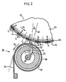
- FIG. 2 there is shown schematically a portion of the magnetic drum 10 seen in section, on a large scale, so that the magnetized areas 14 formed on the surface 13 of this drum have, in this figure, a relatively large size.
- each of these magnetized zones has, in reality, a size of the order of 100 to 200 ⁇ m, that is to say has, for example, a square section of the order of 100 to 200 ⁇ ms aside.
- the magnetized zones which have been shown in FIG. 2 have not been drawn to the scale of the drawing.
- the magnetic drum 10 consists, in a manner known in the prior art, of a cylindrical support 25 formed of a magnetically soft material with high magnetic permeability (such as iron or iron alloy -silicon), this support being coated with a layer 26 of magnetic material with high coercivity such as, for example, the nickel-cobalt magnetic alloy.
- This layer 26 is intended to be magnetized transversely, the support 25 then serving as a magnetic shunt.
- the magnetized zones 14 which are formed on the magnetic drum 10 by the recording member 12 all have magnetization axes NS oriented perpendicular to the surface 13 of the drum.
- the recording member 12 is produced in a known manner, so that these magnetization axes are all oriented in the same direction.
- the magnetized zones 14 all have, on their external face, a south magnetic polarity (S).
- these magnetized zones all have the same magnetization intensity, each of these magnetizations being represented, in FIG. 2, by an arrow whose length is proportional to the value of this magnetization.
- these magnetized zones 14 are shown as they appear after they have passed in front of the application device 15, that is to say after they have been coated with a layer of developer.
- the thickness of this layer is relatively large, that is to say generally greater than a hundred microns, whereas, on the magnetized zones 14 which have passed in front of the retouching device, the thickness of this layer is reduced to a value which, under conditions which will be explained below, can reach around thirty microns.
- the retouching device 20 which equips the printing machine which has just been described comprises an endless transport element 27 which, in the embodiment illustrated in FIG. 2, is in the form of a hollow cylinder, the axis of rotation 28 is parallel to the axis 11 of the drum 10.
- This cylinder which is made of a non-magnetic material such as, for example, aluminum, is disposed along a part 29 of the circular path that follows the surface 13 of the drum during the rotation of this drum, this part 29 situated downstream from the point where the developer particles coming from the reservoir 16 are applied to this surface 13 extending over a length of the order of one at two centimeters.
- the cylinder 27, which is continuously rotated about its axis 28, is placed very close to the surface 13 of the drum 10.
- this cylinder 27 is spaced from the surface 13 by a distance which, practically does not exceed three millimeters. Thus, in the example described, this distance is equal to 1.5 millimeters. It should also be noted that, as can be seen in FIG. 2, the drum 10 and the cylinder 27 both rotate in the same direction, this direction being, in the example described, opposite to that of the needles of a watch. Under these conditions, the external surface 30 of the cylinder 27 passes in front of the path part 29 in a direction opposite to that of the displacement of the surface 13 of the drum. It is useful to indicate here that, in the example described, this surface 13 moves at a linear speed equal to thirty centimeters per second, while the surface 30 of the cylinder 27 moves at a linear speed equal to 1.5 centimeters per second.
- the retouching device which is shown in FIG. 2 further comprises a magnetized element 31, in the form of a bar, which is housed inside the cylinder 27 and is placed near the path portion 29 which has been mentioned. upper.
- This permanent magnet 31 is oriented so that its magnetic pole which is closest to the path part 29 is that whose polarity is opposite to that presented by the magnetized zones 14 on their external face. In other words, the direction of magnetization of this magnet 31 is the same as that of the magnetized zones which pass past it.
- the magnetic pole of the magnet 31 which is closest to the part of the path 29 is that which has a north magnetic polarity (N ′), that is to say here the magnetic pole 32.
- N ′ north magnetic polarity
- the thickness of the cylinder 27 is always very small, this is that is to say generally between one millimeter and a few tenths of a millimeter, and that the end J of this nearest magnetic pole is spaced from the surface 13 of the drum by a distance D, the value of which will be determined a little further , but which, practically, is at most equal to five millimeters.
- the magnetic axis N'S 'of the magnet 31 is not oriented center C of the magnet 31, is normal to the part of the path 29, but is, on the contrary, inclined relative to this normal 40 in the opposite direction to that of the displacement of the surface 13 of the drum.
- This magnetic axis N'S 'then forms with this normal 40 an angle A whose value depends on the linear speed of movement of the surface 13, but does not however exceed 45 degrees.
- this angle A has a value practically equal to 35 degrees.
- this angle A has a value close to 25 degrees.
- the angle A has a value of about 15 degrees.
- Each of the developer particles which have been deposited on the same magnetized zone 14 is attracted to this zone with a force F M whose intensity depends not only on the value of the magnetization of this zone, but also on the distance h that separates this particle from this area.
- this magnetic force F M varies as a function of this distance h, according to a law of variation which is illustrated by the curve in solid lines 50 represented in the diagram of FIG. 3, the coordinates of the constituent points of this curve 50 being related to two axes of rectangular coordinates passing through the same origin 0, this origin 0 corresponding, on the surface 13, to the center of the magnetized zone.
- each magnetized zone 14 has a size close to 100 ⁇ m and where the permanent magnet 31 has a width practically equal to 6 millimeters, it has been found that, to reduce to about thirty of pm the thickness of the developer layer on each of the magnetized zones 14, this magnet 31 had to be spaced from the surface 31 of the drum by a distance D practically equal to 2.5 millimeters.
- the developer particles which remain on the surface 13 of the drum, outside of the magnetized zones 14, are also subjected to the attractive action exerted by the magnet 31 at the moment when they pass directly over this surface. magnet. Because the adhesion force which keeps these particles applied to this surface 13 is significantly less than that exerted by the magnet 31, these particles are detached from this surface and they then come to be applied to the external surface 30 of cylinder 27.
- the surface 30 of the cylinder 27 on which the particles which have been detached from the drum under the action of the magnet 31 are applied is not smooth, but on the contrary has a certain roughness, the gaps between the most highs and the lowest points of this surface 30 however remaining less than 300 microns. Thanks to this roughness, the developer particles which have applied to the surface 30 are entrained during the rotation of the cylinder 27. A squeegee 34, the end of which is pressed against the surface 30, then allows these particles to 'be removed from the cylinder 27 and fall back into the tank 16, as can be seen in Figure 1.
- the retouching device which has just been described applies not only to a printing machine, the recording medium of which is constituted by a magnetic drum, but also to a printing machine, of which the recording medium is constituted, as as shown in FIG. 3, by an endless magnetic strip 110 stretched on rollers 111, 112, 113, 114, this strip being held pressed against a magnetic shunt 115 made up of a bar of magnetically soft material with high magnetic permeability.
- the printing machine which is shown schematically in Figure 3 has the same components as those of the machine shown in Figure 1, such as, for example, the magnetic recording member 12, the application device 15, etc. ....
- the running of this strip 110, in the direction indicated by the arrow D1 is provided by an electric motor, not shown, which drives one of the rollers in rotation, the other rollers being free to rotate.
- the printing machine which is shown in FIG. 3 can, of course, be equipped with the same retouching device as that which has been illustrated in FIG. 2.
- this retouching device 20 comprises, as can be seen in FIG. 3, a transport element in the form of an endless belt 127 stretched over three rollers 128, 129, 130, this strip 127 consisting of a flexible non-magnetic material such as, for example, rubber.
- the rollers 129 and 130 are arranged so that the portion of the strip 127 which is between these two rollers is parallel to a part 29 of the path followed by the magnetic strip 110 between the rollers 111 and 114 and is located in the immediate vicinity of this part 29.
- the endless strip 127 is driven in one direction, indicated by the arrow D2 in FIG.
- the permanent magnet 31 which is placed inside the path followed by the strip 127 and near the part 29 is oriented, as can be seen in FIG. 3 , so that its magnetic pole which is closest to this part 29 is the one whose polarity is opposite to that presented by the magnetized zones opposite the strip 127. It is also seen in FIG. 3, that the axis magnetic of magnet 31 is inclined with respect to the straight line 40 which, passing through the center C of this magnet, is normal to the part 29, this inclination being carried out in the opposite direction to that of the displacement of the magnetic strip 110. This magnetic axis then forms with the straight 40 and an angle A whose value, defined above in the text, depends on the speed of movement of the magnetic strip 110, but does not exceed 45 degrees.
- the retouching device of the present invention it has been successful not only to remove the developer particles deposited outside the magnetized areas of the magnetic recording medium, but also to significantly reduce the thickness of the developer layer on each of these magnetized areas. This is how we were able, for example, on magnetized zones having a size of the order of 100 to 200 microns, reduce the thickness of the developer layer deposited on these areas from 100 to 30 microns.
- the retouching device of the invention allows the developer particles remaining on the magnetized areas to regroup towards the centers of these areas, which further improves the quality of the impression obtained during the transfer of these particles onto the paper.
Landscapes
- Physics & Mathematics (AREA)
- General Physics & Mathematics (AREA)
- Magnetic Brush Developing In Electrophotography (AREA)
- Printers Or Recording Devices Using Electromagnetic And Radiation Means (AREA)
- Silver Salt Photography Or Processing Solution Therefor (AREA)
Claims (8)
Priority Applications (1)
| Application Number | Priority Date | Filing Date | Title |
|---|---|---|---|
| AT84402286T ATE31982T1 (de) | 1983-11-17 | 1984-11-13 | Entwicklungsvorrichtung von latenten magnetischen abbildungen. |
Applications Claiming Priority (2)
| Application Number | Priority Date | Filing Date | Title |
|---|---|---|---|
| FR8318282A FR2555329B1 (fr) | 1983-11-17 | 1983-11-17 | Appareil de developpement d'images magnetiques latentes |
| FR8318282 | 1983-11-17 |
Publications (2)
| Publication Number | Publication Date |
|---|---|
| EP0142446A1 EP0142446A1 (de) | 1985-05-22 |
| EP0142446B1 true EP0142446B1 (de) | 1988-01-13 |
Family
ID=9294219
Family Applications (1)
| Application Number | Title | Priority Date | Filing Date |
|---|---|---|---|
| EP84402286A Expired EP0142446B1 (de) | 1983-11-17 | 1984-11-13 | Entwicklungsvorrichtung von latenten magnetischen Abbildungen |
Country Status (6)
| Country | Link |
|---|---|
| US (1) | US4610527A (de) |
| EP (1) | EP0142446B1 (de) |
| AT (1) | ATE31982T1 (de) |
| DE (1) | DE3468755D1 (de) |
| ES (1) | ES8600816A1 (de) |
| FR (1) | FR2555329B1 (de) |
Families Citing this family (4)
| Publication number | Priority date | Publication date | Assignee | Title |
|---|---|---|---|---|
| FR2625574B1 (fr) * | 1987-12-30 | 1990-09-14 | Bull Sa | Dispositif pour eliminer la pollution due aux charges electriques acquises par un support d'impression dans une machine imprimante magnetographique |
| FR2629606B1 (fr) * | 1988-03-30 | 1990-11-09 | Bull Sa | Dispositif pour former des images latentes magnetiques sur l'element d'enregistrement d'une imprimante magnetographique |
| DE69218689T2 (de) * | 1991-07-26 | 1997-07-24 | Matsushita Electric Industrial Co., Ltd., Kadoma, Osaka | Elektrophotographisches Verfahren und Gerät hierfür |
| KR0159306B1 (ko) * | 1993-01-13 | 1999-03-20 | 모리시타 요이찌 | 전자사진장치 |
Family Cites Families (6)
| Publication number | Priority date | Publication date | Assignee | Title |
|---|---|---|---|---|
| US3804511A (en) * | 1970-07-29 | 1974-04-16 | Pelorex Corp | Method and apparatus utilizing magnetic storage for transferring graphical information |
| US4108546A (en) * | 1976-11-01 | 1978-08-22 | Xerox Corporation | Cleaning apparatus and electrostatographic reproducing machine |
| US4314018A (en) * | 1977-04-19 | 1982-02-02 | Mita Industrial Company, Ltd. | Cleaning process for an electrostatic copying apparatus |
| US4127327A (en) * | 1977-06-20 | 1978-11-28 | Xerox Corporation | Apparatuses incorporating a composite support member |
| JPH0244304Y2 (de) * | 1980-08-30 | 1990-11-26 | ||
| DE3119029C2 (de) * | 1981-05-13 | 1983-02-10 | Siemens AG, 1000 Berlin und 8000 München | Vorrichtung zur Entwicklung von auf einem Ladungsbildträger angeordneten Ladungsbildern mit Hilfe eines aus Toner und Trägerteilchen bestehenden Entwicklergemisches |
-
1983
- 1983-11-17 FR FR8318282A patent/FR2555329B1/fr not_active Expired
-
1984
- 1984-10-19 US US06/662,909 patent/US4610527A/en not_active Expired - Lifetime
- 1984-11-13 DE DE8484402286T patent/DE3468755D1/de not_active Expired
- 1984-11-13 EP EP84402286A patent/EP0142446B1/de not_active Expired
- 1984-11-13 AT AT84402286T patent/ATE31982T1/de not_active IP Right Cessation
- 1984-11-16 ES ES537747A patent/ES8600816A1/es not_active Expired
Also Published As
| Publication number | Publication date |
|---|---|
| ATE31982T1 (de) | 1988-01-15 |
| ES537747A0 (es) | 1985-10-16 |
| ES8600816A1 (es) | 1985-10-16 |
| FR2555329A1 (fr) | 1985-05-24 |
| FR2555329B1 (fr) | 1986-02-14 |
| DE3468755D1 (en) | 1988-02-18 |
| EP0142446A1 (de) | 1985-05-22 |
| US4610527A (en) | 1986-09-09 |
Similar Documents
| Publication | Publication Date | Title |
|---|---|---|
| CH639501A5 (fr) | Procede de developpement d'images electrostatiques latentes et dispositif pour sa mise en oeuvre. | |
| FR2564609A1 (fr) | Procede et appareil de developpement | |
| FR2594566A1 (fr) | Procede et appareil de developpement d'une image electrostatique latente | |
| FR2597625A1 (fr) | Appareil pour developper une image electrostatique latente, notamment en electrocopie | |
| FR2477734A1 (fr) | Appareil pour developper une image electrostatique latente | |
| EP0142446B1 (de) | Entwicklungsvorrichtung von latenten magnetischen Abbildungen | |
| FR2482737A1 (fr) | Feuille de support d'image electrostatique, procede et appareil de fabrication d'une telle feuille, et procede et appareil de formation d'images par electrophotographie | |
| EP0086683B1 (de) | Vorrichtung zum Aufbringen von Feststoffteilchen auf einen Aufzeichnungsträger einer Druckvorrichtung | |
| FR2503408A1 (de) | ||
| EP0315509B1 (de) | Verfahren zum Fixieren eines auf einem Blatt gelegenen Pulverentwicklers und Vorrichtung zum Fixieren dieses Entwicklers nach diesem Verfahren | |
| CH630185A5 (fr) | Installation pour la reproduction electrophotographique d'une image et procede pour sa mise en action. | |
| EP0328428A1 (de) | Vorrichtung zum periodischen Auftragen von Teilchen eines pulverförmigen Entwicklers auf den Aufnahmeträger eines magnetographischen Druckers | |
| EP0099763B1 (de) | Einrichtung zum Anbringen von Entwicklungspulver auf der Aufzeichnungsrolle eines nichtmechanischen Druckers | |
| EP0291392B1 (de) | Pulverförmige Substanz zur Reibungsverminderung des Aufnahmeträgers eines magnetischen Druckers | |
| EP0082742B1 (de) | Verfahren und Vorrichtung zum magnetographischen Kopieren | |
| EP0082740B1 (de) | Verfahren und Vorrichtung zum magnetographischen Kopieren | |
| EP0082741B1 (de) | Verfahren und Vorrichtung zum magnetographischen Kopieren | |
| EP0082739B1 (de) | Verfahren und Vorrichtung zum magnetographischen Kopieren | |
| FR2637992A1 (fr) | Tete d'enregistrement electrostatique, dispositif d'enregistrement d'images et dispositif d'affichage comportant une telle tete, dispositif d'alimentation d'un agent de developpement utilise dans une telle tete et procede pour fabriquer cette derniere | |
| EP0172767B1 (de) | Verfahren und Gerät zum magnetographischen Kopieren | |
| FR2625574A1 (fr) | Dispositif pour eliminer la pollution due aux charges electriques acquises par un support d'impression dans une machine imprimante magnetographique | |
| FR2522838A1 (fr) | Dispositif a moyens de redressement de lignes de force, pour la revelation d'images latentes magnetiques portees par un support magnetique a magnetisation transversale | |
| CH622365A5 (en) | Method for reproducing an image on a transfer medium | |
| FR2581772A1 (fr) | Procede d'electrocopie | |
| FR2545951A1 (fr) | Procede de developpement d'une image latente formee sur une surface magnetique, dispositif pour la mise en oeuvre du procede et appareil d'impression comportant ledit dispositif |
Legal Events
| Date | Code | Title | Description |
|---|---|---|---|
| PUAI | Public reference made under article 153(3) epc to a published international application that has entered the european phase |
Free format text: ORIGINAL CODE: 0009012 |
|
| AK | Designated contracting states |
Designated state(s): AT BE CH DE GB IT LI NL SE |
|
| 17P | Request for examination filed |
Effective date: 19850419 |
|
| 17Q | First examination report despatched |
Effective date: 19860929 |
|
| RAP1 | Party data changed (applicant data changed or rights of an application transferred) |
Owner name: BULL S.A. |
|
| ITF | It: translation for a ep patent filed | ||
| GRAA | (expected) grant |
Free format text: ORIGINAL CODE: 0009210 |
|
| AK | Designated contracting states |
Kind code of ref document: B1 Designated state(s): AT BE CH DE GB IT LI NL SE |
|
| REF | Corresponds to: |
Ref document number: 31982 Country of ref document: AT Date of ref document: 19880115 Kind code of ref document: T |
|
| GBT | Gb: translation of ep patent filed (gb section 77(6)(a)/1977) | ||
| REF | Corresponds to: |
Ref document number: 3468755 Country of ref document: DE Date of ref document: 19880218 |
|
| PLBE | No opposition filed within time limit |
Free format text: ORIGINAL CODE: 0009261 |
|
| STAA | Information on the status of an ep patent application or granted ep patent |
Free format text: STATUS: NO OPPOSITION FILED WITHIN TIME LIMIT |
|
| 26N | No opposition filed | ||
| ITTA | It: last paid annual fee | ||
| EAL | Se: european patent in force in sweden |
Ref document number: 84402286.3 |
|
| PGFP | Annual fee paid to national office [announced via postgrant information from national office to epo] |
Ref country code: SE Payment date: 19981019 Year of fee payment: 15 |
|
| PGFP | Annual fee paid to national office [announced via postgrant information from national office to epo] |
Ref country code: AT Payment date: 19981030 Year of fee payment: 15 |
|
| PGFP | Annual fee paid to national office [announced via postgrant information from national office to epo] |
Ref country code: BE Payment date: 19981109 Year of fee payment: 15 |
|
| PGFP | Annual fee paid to national office [announced via postgrant information from national office to epo] |
Ref country code: CH Payment date: 19981110 Year of fee payment: 15 |
|
| PGFP | Annual fee paid to national office [announced via postgrant information from national office to epo] |
Ref country code: NL Payment date: 19981130 Year of fee payment: 15 |
|
| PG25 | Lapsed in a contracting state [announced via postgrant information from national office to epo] |
Ref country code: AT Free format text: LAPSE BECAUSE OF NON-PAYMENT OF DUE FEES Effective date: 19991113 |
|
| PG25 | Lapsed in a contracting state [announced via postgrant information from national office to epo] |
Ref country code: SE Free format text: LAPSE BECAUSE OF NON-PAYMENT OF DUE FEES Effective date: 19991114 |
|
| PG25 | Lapsed in a contracting state [announced via postgrant information from national office to epo] |
Ref country code: LI Free format text: LAPSE BECAUSE OF NON-PAYMENT OF DUE FEES Effective date: 19991130 Ref country code: CH Free format text: LAPSE BECAUSE OF NON-PAYMENT OF DUE FEES Effective date: 19991130 Ref country code: BE Free format text: LAPSE BECAUSE OF NON-PAYMENT OF DUE FEES Effective date: 19991130 |
|
| BERE | Be: lapsed |
Owner name: S.A. BULL Effective date: 19991130 |
|
| PG25 | Lapsed in a contracting state [announced via postgrant information from national office to epo] |
Ref country code: NL Free format text: LAPSE BECAUSE OF NON-PAYMENT OF DUE FEES Effective date: 20000601 |
|
| REG | Reference to a national code |
Ref country code: GB Ref legal event code: 732E |
|
| REG | Reference to a national code |
Ref country code: CH Ref legal event code: PL |
|
| EUG | Se: european patent has lapsed |
Ref document number: 84402286.3 |
|
| NLV4 | Nl: lapsed or anulled due to non-payment of the annual fee |
Effective date: 20000601 |
|
| PGFP | Annual fee paid to national office [announced via postgrant information from national office to epo] |
Ref country code: GB Payment date: 20001127 Year of fee payment: 17 |
|
| PGFP | Annual fee paid to national office [announced via postgrant information from national office to epo] |
Ref country code: DE Payment date: 20010126 Year of fee payment: 17 |
|
| PG25 | Lapsed in a contracting state [announced via postgrant information from national office to epo] |
Ref country code: GB Free format text: LAPSE BECAUSE OF NON-PAYMENT OF DUE FEES Effective date: 20011113 |
|
| REG | Reference to a national code |
Ref country code: GB Ref legal event code: IF02 |
|
| PG25 | Lapsed in a contracting state [announced via postgrant information from national office to epo] |
Ref country code: DE Free format text: LAPSE BECAUSE OF NON-PAYMENT OF DUE FEES Effective date: 20020702 |