EP0142461A2 - Verfahren und Vorrichtung zum Einstellen der Quersiegel- und Trennlage bei endlos laufenden Schlauchbeutelpackungen - Google Patents
Verfahren und Vorrichtung zum Einstellen der Quersiegel- und Trennlage bei endlos laufenden Schlauchbeutelpackungen Download PDFInfo
- Publication number
- EP0142461A2 EP0142461A2 EP84810380A EP84810380A EP0142461A2 EP 0142461 A2 EP0142461 A2 EP 0142461A2 EP 84810380 A EP84810380 A EP 84810380A EP 84810380 A EP84810380 A EP 84810380A EP 0142461 A2 EP0142461 A2 EP 0142461A2
- Authority
- EP
- European Patent Office
- Prior art keywords
- drive
- tubular bag
- angular position
- sensor
- speed
- Prior art date
- Legal status (The legal status is an assumption and is not a legal conclusion. Google has not performed a legal analysis and makes no representation as to the accuracy of the status listed.)
- Granted
Links
Images
Classifications
-
- B—PERFORMING OPERATIONS; TRANSPORTING
- B65—CONVEYING; PACKING; STORING; HANDLING THIN OR FILAMENTARY MATERIAL
- B65B—MACHINES, APPARATUS OR DEVICES FOR, OR METHODS OF, PACKAGING ARTICLES OR MATERIALS; UNPACKING
- B65B41/00—Supplying or feeding container-forming sheets or wrapping material
- B65B41/18—Registering sheets, blanks, or webs
Definitions
- the present invention relates to a method for adjusting the transverse sealing and separating position in the case of endless tubular bag packs according to the preamble of independent claim 1 and to an apparatus for carrying out the method according to claim 9.
- tubular bag packs as described, for example, in CH-A 527 090, a film web is drawn through a folding box in order to form a tube from this film web.
- the items to be packaged are fed continuously to this tube at regular intervals.
- the filled tube is then divided into individual packs by transverse sealing seams and mostly the packs are separated at the same time as the sealing. According to this publication, up to about 300-400 packs per minute can be produced in this way.
- the film web is printed, it must of course be ensured that the motifs are always arranged the same.
- the lengths can change greatly as a result of fluctuations in the tensile stress, so that an exact setting of the sealing and separating position is necessary.
- the object of the invention is to continuously correct an incorrect position of the marks with respect to a cutting point.
- the device for performing the method is characterized in claim 9.
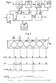
- triangular-closed arrows when filled, mean the material flow, and when they are empty, the energy flow, open arrows, on the other hand, mean the information flow.
- the energy is fed in at N.
- tubular bag packing part A a tubular bag transport part B, an optoelectric sensor C and a transverse sealing and separating part D as well as a main drive E, a second drive H, a computer R and an input and display part J are shown schematically from a tubular bag packaging machine.
- the machine status MC namely "stands still” - “runs” - manual drive "-” machine stop "in addition to the freely selectable parameters from the input and display part J, in addition to the data on the angular position Fi of the film pattern Z and the marks M (Fig. 2) and those Entered via the angular position Ms of the hose P and via the speed nMi of the machine, the letters i, s behind the device designation indicating whether it is an actual value or a setpoint.
- the second drive H receives information about the required speed nFs from the computer R. Electrical energy flows from the two feed points N shown separately into the drives E, H, which is transmitted as mechanical energy with a main shaft, tubular bag packing part A and to the transverse sealing and separating part D.
- the transport part B is directly controlled by the second drive H and the speed is independently kept constant.
- a disc rotor motor can be used as the drive machine for the second drive.
- the information about the angular position ⁇ Mi is represented by 360 pulses per revolution of the shaft. These can be generated by means of an angle encoder, by means of a step pulse generator or also using an inductive pulse generator.
- Tachometers can be used to output the speed information nMi and nFi.
- a potentiometer for emitting an adjustable constant voltage can be provided for the input of the speed of the machine nMs.
- the mode of operation is described with reference to FIG. 2.
- a tubular bag band P which is to move from right to left.
- the optoelectric sensor C and the transverse sealing and separating part D of the machine are shown.
- the marks M and the motifs or figures F are indicated on the tubular bag band P.
- the first line shows the pulses ⁇ Ms from the cross seal and separating part D, which have a variable distance here.
- the pulses ⁇ Fi in the second line are the pulses from the sensor C and coincide with the marks M in time.
Landscapes
- Engineering & Computer Science (AREA)
- Mechanical Engineering (AREA)
- Containers And Plastic Fillers For Packaging (AREA)
- Lining Or Joining Of Plastics Or The Like (AREA)
Abstract
Description
- Die vorliegende Erfindung betrifft ein Verfahren zum Einstellen der Quersiegel- und Trennlage bei endlosen Schlauchbeutelpackungen gemäss dem Oberbegriff des unabhängigen Patentanspruchs 1 sowie eine Vorrichtung zur Durchführung des Verfahrens gemäss Patentanspruch 9.
- Bei Schlauchbeutelpackungen, wie sie beispielsweise in der CH-A 527 090 beschrieben sind, wird eine Folienbahn durch einen Faltkasten gezogen, um aus dieser Folienbahn einen Schlauch zu bilden. Diesem Schlauch werden mit regelmässigem Abstand die zu verpackenden Gegenstände kontinuierlich zugeführt. Der gefüllte Schlauch wird dann durch Quersiegelnähte in einzelne Packungen unterteilt und meist gleichzeitig mit der Siegelung werden die Packungen abgetrennt. Gemäss dieser Veröffentlichung können auf diese Weise bis zu etwa 300 - 400 Packungen pro Minute hergestellt werden.
- Wenn die Folienbahn bedruckt ist, muss natürlich beachtet werden, dass die Motive immer gleich angeordnet sind. Insbesondere bei Verwendung von Kunststoffolien können sich die Längen infolge Schwankungen der Zugspannung stark ändern, so dass eine genaue Einstellung der Siegel- und Trennlage notwendig ist.
- Aus der DE-A 29 51 178 und aus der EP-A 11 595 ist es bekannt, auf die Folien eine Marke aufzubringen und diese durch einen Sensor auszuwerten, um immer an der richtigen Stelle zu siegeln und zu trennen. Gemäss der erstgenannten Anordnung wird die Abweichung in der Länge der einzelnen Abschnitte quantisiert und entweder wird die Geschwindigkeit der Schneidemittel und/oder der Transportmittel verändert. Dazu ist ein Schrittmotor vorhanden, der auf ein Differentialgetriebe einwirkt, um zusammen mit dem mechanischen Ausgang des Hauptmotors diese Veränderung zu bewirken. Ebenso ist in der zweitgenannten Veröffentlichung ein Differentialantrieb mit einem Schrittmotor vorgesehen, jedoch ist hier angenommen dass eine Verpackung falsch ist und ausgestossen werden muss.
- Demgegenüber stellt sich für die Erfindung die Aufgabe, eine falsche Lage der Marken bezüglich einer Schneidstelle kontinuierlich auszugleichen.
- Erfindungsgemäss wird diese Aufgabe durch die Merkmale im kennzeichnenden Teil des unabhängigen Patentanspruchs 1 gelöst.
- Die Vorrichtung zur Durchführung des Verfahrens ist im Patentanspruch 9 gekennzeichnet.
- Ein Ausführungsbeispiel der Erfindung wird nachfolgend anhand der Zeichnung erläutert. Es zeigen:
- Fig. 1 ein Blockschema zur Darstellung des Informationsflusses in einer Vorrichtung zur Durchführung des erfindungsgemässen Verfahrens, und
- Fig. 2 Diagramme zur Erläuterung der Erfindung.
- In Fig. 1 bedeuten dreieckig-geschlossene Pfeile, wenn sie ausgefüllt sind, den Materialfluss, und wenn sie leer sind, den Energiefluss, offene Pfeile hingegen bedeuten den Informationsfluss. Die Energie-Einspeisung erfolgt bei N.
- Von einer Schlauchbeutel-Verpackungsmaschine sind der Schlauchbeutelpackungsteil A, ein Schlauchbeuteltransportteil B, ein optoelektrischer Sensor C und ein Quersiegel-und Trennteil D sowie ein Hauptantrieb E, ein zweiter Antrieb H, ein Rechner R und ein Eingabe- und Anzeigeteil J schematisch dargestellt.
- Als wichtige Informationen werden dem Rechner R der Maschinenzustand MC; nämlich "steht still" - "läuft" - Handantrieb" - "Maschinenhalt" neben den frei wählbaren Parametern aus dem Eingabe- und Anzeigeteil J, neben den Daten über die Winkellage Fi des Folienmusters Z und der Marken M (Fig. 2) und denen über die Winkellage Ms des Schlauches P und über die Drehzahl nMi der Maschine eingegeben. Dabei bedeuten die Buchstaben i,s jeweils hinter der Gerätebezeichnung ob es sich um einen Istwert oder um einen Sollwert handelt.
- Der zweite Antrieb H erhält aus dem Rechner R eine Information über die benötigte Drehzahl nFs. Aus den beiden getrennt dargestellten Speisestellen N fliesst elektrische Energie in die Antriebe E, H, die als mechanische Energie mit einer Hauptwelle Schlauchbeutelpackungsteil A und auf den Quersiegel- und Trennteil D übertragen wird. Vom zweiten Antrieb H wird der Transportteil B direkt angesteuert und die Drehzahl wird selbständig konstant gehalten. Als Antriebsmaschine für den zweiten Antrieb kann ein Scheibenläufermotor verwendet werden.
- Die Information über die Winkellage ϕMi wird mittels 360 Impulsen pro Umdrehung der Welle dargestellt. Diese können mittels eines Winkelkodierers , mittels eines Schrittimpulsgebers oder auch mit einem induktiven Impulsgeber erzeugt werden.
- Für die Abgabe der Drehzahlinformationen nMi und nFi können Tachometer verwendet werden. Für die Eingabe der Drehzahl der Maschine nMs kann ein Potentiometer zur Abgabe einer einstellbaren konstanten Spannung vorgesehen sein.
- Die Arbeitsweise wird an Hand von Fig. 2 beschrieben. Oben am Bild ist ein Schlauchbeutelband P dargestellt, das sich von rechts nach links bewegen soll. Es wird der optoelektrische Sensor C und der Quersiegel- und Trennteil D der Maschine dargestellt. Auf dem Schlauchbeutelband P sind die Marken M und die Motive oder Figuren F angedeutet.
- In der ersten Zeile sind die Impulse ϕMs aus dem Quersiegel-und Trennteil D dargestellt, die hier einen variablen Abstand haben. Die Impulse ϕFi der zweiten Zeile sind die Impulse aus dem Sensor C und stimmen zeitlich mit den Marken M überein. Im Rechner wird die zeitliche Differenz S der beiden Impulse ϕMs -ϕFi gebildet und durch Integration U=fsdt wird dasFehlersignal und daraus die gewünschte Drehzahl nFs für den Transportteil B bestimmt.
- Dies zeigt deutlich, dass mit der Erfindung alle mechanischen Teile für die Drehzahländerung wegfallen und nur eine einfache, sich rasch einstellende Impulssteuerung benötigt wird.
Claims (10)
Applications Claiming Priority (2)
| Application Number | Priority Date | Filing Date | Title |
|---|---|---|---|
| CH4818/83 | 1983-09-01 | ||
| CH481883 | 1983-09-01 |
Publications (3)
| Publication Number | Publication Date |
|---|---|
| EP0142461A2 true EP0142461A2 (de) | 1985-05-22 |
| EP0142461A3 EP0142461A3 (en) | 1986-05-14 |
| EP0142461B1 EP0142461B1 (de) | 1988-10-05 |
Family
ID=4283071
Family Applications (1)
| Application Number | Title | Priority Date | Filing Date |
|---|---|---|---|
| EP19840810380 Expired EP0142461B1 (de) | 1983-09-01 | 1984-08-03 | Verfahren und Vorrichtung zum Einstellen der Quersiegel- und Trennlage bei endlos laufenden Schlauchbeutelpackungen |
Country Status (4)
| Country | Link |
|---|---|
| EP (1) | EP0142461B1 (de) |
| JP (1) | JPS6077841A (de) |
| BR (1) | BR8404296A (de) |
| DE (1) | DE3474430D1 (de) |
Cited By (4)
| Publication number | Priority date | Publication date | Assignee | Title |
|---|---|---|---|---|
| EP0274849A1 (de) * | 1986-12-15 | 1988-07-20 | Kliklok Corporation | Apparat und Verfahren zum Zuführen eines Verpackungsfilms |
| EP0348065A1 (de) * | 1988-06-20 | 1989-12-27 | Hayssen Manufacturing Company | Anordnung und Verfahren zum Regeln einer Vorrichtung für das Versiegeln von Packungen |
| WO1995009121A1 (fr) * | 1993-09-29 | 1995-04-06 | Kustner Industries S.A. | Dispositif de controle de l'avance du film d'emballage dans une machine a emballer, et procede de controle correspondant |
| WO2012163673A3 (de) * | 2011-06-03 | 2013-01-24 | Robert Bosch Gmbh | Verfahren zur erfassung der querposition von einem packstoff, insbesondere einer folienverpackung, sowie entsprechende vorrichtung und entsprechender packstoff |
Family Cites Families (2)
| Publication number | Priority date | Publication date | Assignee | Title |
|---|---|---|---|---|
| US2529161A (en) * | 1948-04-30 | 1950-11-07 | Gen Electric | Register control system |
| US2599430A (en) * | 1950-03-29 | 1952-06-03 | Du Pont | Register control system for web cutting mechanisms |
-
1984
- 1984-08-03 EP EP19840810380 patent/EP0142461B1/de not_active Expired
- 1984-08-03 DE DE8484810380T patent/DE3474430D1/de not_active Expired
- 1984-08-28 BR BR8404296A patent/BR8404296A/pt not_active IP Right Cessation
- 1984-08-30 JP JP17946684A patent/JPS6077841A/ja active Pending
Cited By (5)
| Publication number | Priority date | Publication date | Assignee | Title |
|---|---|---|---|---|
| EP0274849A1 (de) * | 1986-12-15 | 1988-07-20 | Kliklok Corporation | Apparat und Verfahren zum Zuführen eines Verpackungsfilms |
| EP0348065A1 (de) * | 1988-06-20 | 1989-12-27 | Hayssen Manufacturing Company | Anordnung und Verfahren zum Regeln einer Vorrichtung für das Versiegeln von Packungen |
| WO1995009121A1 (fr) * | 1993-09-29 | 1995-04-06 | Kustner Industries S.A. | Dispositif de controle de l'avance du film d'emballage dans une machine a emballer, et procede de controle correspondant |
| WO2012163673A3 (de) * | 2011-06-03 | 2013-01-24 | Robert Bosch Gmbh | Verfahren zur erfassung der querposition von einem packstoff, insbesondere einer folienverpackung, sowie entsprechende vorrichtung und entsprechender packstoff |
| CN103748015A (zh) * | 2011-06-03 | 2014-04-23 | 罗伯特·博世有限公司 | 用于检测包装材料、尤其是薄膜包装的横向位置的方法 |
Also Published As
| Publication number | Publication date |
|---|---|
| DE3474430D1 (en) | 1988-11-10 |
| EP0142461A3 (en) | 1986-05-14 |
| EP0142461B1 (de) | 1988-10-05 |
| BR8404296A (pt) | 1985-07-30 |
| JPS6077841A (ja) | 1985-05-02 |
Similar Documents
| Publication | Publication Date | Title |
|---|---|---|
| DE3937069C2 (de) | Verfahren und Vorrichtung zum Ausgleich von Vorschubabweichungen in beiden Richtungen bei taktgeförderten Materialbahnen | |
| DE2951178C2 (de) | ||
| DE68910390T2 (de) | Anordnung und Verfahren zum Regeln einer Vorrichtung für das Versiegeln von Packungen. | |
| DE3542923C2 (de) | ||
| DE3587719T2 (de) | Kaschiervorrichtung mit Ausdehnungsüberwachung. | |
| DE69215059T2 (de) | Mikroprozessor gesteuerter SCR-Antriebsmotor für Verpackungsmaschinen | |
| DE4337514A1 (de) | Rechnergesteuerte Horizontal-Verpackungseinrichtung | |
| DE3006344A1 (de) | Vorrichtung zum schneiden von papierbahnen | |
| DE2442901C3 (de) | ||
| DE3621556A1 (de) | Rechnergesteuerte horizontal-verpackungsmaschine | |
| DE3878224T2 (de) | Verpackungsmaschine mit einer einrichtung zur verhinderung des einklemmens zu verpackender gegenstaende in einen endversiegelungsmechanismus. | |
| DE3902501C2 (de) | Verpackungsverfahren | |
| DE3934876A1 (de) | Verpackungsverfahren und verpackungsvorrichtung | |
| DE2729815A1 (de) | Vorrichtung zum schneiden von kontinuierlich bewegtem blattmaterial durch duesenstrahl eines unter hochdruck stehenden fluidmittels | |
| DE4040558A1 (de) | Verpackungsmaschine | |
| DE1523549B2 (de) | Einrichtung zur regelung einer physikalischen groesse an nacheinander in einer anlage herzustellenden gegenstaenden | |
| DE102014221353A1 (de) | Schweißbacken für eine Verpackungsmaschine | |
| CH677344A5 (de) | ||
| DE3744457A1 (de) | Vorrichtung zur herstellung von blisterpackungen | |
| DE3937536A1 (de) | Beutelherstellmaschine | |
| EP0142461A2 (de) | Verfahren und Vorrichtung zum Einstellen der Quersiegel- und Trennlage bei endlos laufenden Schlauchbeutelpackungen | |
| EP1216817A2 (de) | Vorrichtung zum Herstellen von Verpackungsbeuteln | |
| DE2020199B2 (de) | Querschneider mit gesteuertem Mehrmotorenantrieb zum Schneiden gleichlanger Bogen | |
| EP0006852B1 (de) | Verfahren und Vorrichtung zum Zerschneiden eines aus mehreren Streifen aus Papier, Pappe od.dgl. schraubenförmig gewickelten Rohres in einzelne Abschnitte | |
| DE3822915A1 (de) | Automatisches schweissverfahren |
Legal Events
| Date | Code | Title | Description |
|---|---|---|---|
| PUAI | Public reference made under article 153(3) epc to a published international application that has entered the european phase |
Free format text: ORIGINAL CODE: 0009012 |
|
| AK | Designated contracting states |
Designated state(s): CH DE FR GB IT LI NL |
|
| PUAL | Search report despatched |
Free format text: ORIGINAL CODE: 0009013 |
|
| AK | Designated contracting states |
Kind code of ref document: A3 Designated state(s): CH DE FR GB IT LI NL |
|
| 17P | Request for examination filed |
Effective date: 19861020 |
|
| 17Q | First examination report despatched |
Effective date: 19870422 |
|
| GRAA | (expected) grant |
Free format text: ORIGINAL CODE: 0009210 |
|
| AK | Designated contracting states |
Kind code of ref document: B1 Designated state(s): CH DE FR GB IT LI NL |
|
| PG25 | Lapsed in a contracting state [announced via postgrant information from national office to epo] |
Ref country code: FR Free format text: THE PATENT HAS BEEN ANNULLED BY A DECISION OF A NATIONAL AUTHORITY Effective date: 19881005 |
|
| REF | Corresponds to: |
Ref document number: 3474430 Country of ref document: DE Date of ref document: 19881110 |
|
| GBT | Gb: translation of ep patent filed (gb section 77(6)(a)/1977) | ||
| ITF | It: translation for a ep patent filed | ||
| EN | Fr: translation not filed | ||
| PLBE | No opposition filed within time limit |
Free format text: ORIGINAL CODE: 0009261 |
|
| STAA | Information on the status of an ep patent application or granted ep patent |
Free format text: STATUS: NO OPPOSITION FILED WITHIN TIME LIMIT |
|
| PG25 | Lapsed in a contracting state [announced via postgrant information from national office to epo] |
Ref country code: LI Effective date: 19890831 Ref country code: CH Effective date: 19890831 |
|
| 26N | No opposition filed | ||
| REG | Reference to a national code |
Ref country code: CH Ref legal event code: PL |
|
| PGFP | Annual fee paid to national office [announced via postgrant information from national office to epo] |
Ref country code: GB Payment date: 19900711 Year of fee payment: 7 |
|
| PGFP | Annual fee paid to national office [announced via postgrant information from national office to epo] |
Ref country code: DE Payment date: 19900730 Year of fee payment: 7 |
|
| ITTA | It: last paid annual fee | ||
| PGFP | Annual fee paid to national office [announced via postgrant information from national office to epo] |
Ref country code: NL Payment date: 19900831 Year of fee payment: 7 |
|
| PG25 | Lapsed in a contracting state [announced via postgrant information from national office to epo] |
Ref country code: GB Effective date: 19910803 |
|
| PG25 | Lapsed in a contracting state [announced via postgrant information from national office to epo] |
Ref country code: NL Effective date: 19920301 |
|
| GBPC | Gb: european patent ceased through non-payment of renewal fee | ||
| NLV4 | Nl: lapsed or anulled due to non-payment of the annual fee | ||
| PG25 | Lapsed in a contracting state [announced via postgrant information from national office to epo] |
Ref country code: DE Effective date: 19920501 |