EP0142472A2 - Dispositif pour séparer et alimenter des feuilles dans une machine de bureau - Google Patents
Dispositif pour séparer et alimenter des feuilles dans une machine de bureau Download PDFInfo
- Publication number
- EP0142472A2 EP0142472A2 EP84810540A EP84810540A EP0142472A2 EP 0142472 A2 EP0142472 A2 EP 0142472A2 EP 84810540 A EP84810540 A EP 84810540A EP 84810540 A EP84810540 A EP 84810540A EP 0142472 A2 EP0142472 A2 EP 0142472A2
- Authority
- EP
- European Patent Office
- Prior art keywords
- intermediate frame
- roller
- separating
- shaft
- stack
- Prior art date
- Legal status (The legal status is an assumption and is not a legal conclusion. Google has not performed a legal analysis and makes no representation as to the accuracy of the status listed.)
- Withdrawn
Links
Images


Classifications
-
- B—PERFORMING OPERATIONS; TRANSPORTING
- B41—PRINTING; LINING MACHINES; TYPEWRITERS; STAMPS
- B41J—TYPEWRITERS; SELECTIVE PRINTING MECHANISMS, i.e. MECHANISMS PRINTING OTHERWISE THAN FROM A FORME; CORRECTION OF TYPOGRAPHICAL ERRORS
- B41J13/00—Devices or arrangements of selective printing mechanisms, e.g. ink-jet printers or thermal printers, specially adapted for supporting or handling copy material in short lengths, e.g. sheets
- B41J13/10—Sheet holders, retainers, movable guides, or stationary guides
- B41J13/103—Sheet holders, retainers, movable guides, or stationary guides for the sheet feeding section
Definitions
- the object of the invention is to improve a device of the type mentioned at the outset while maintaining the drive from the platen roller and the possibility of separating the office machine, intermediate frame and separating assembly in such a way that the drive is simplified and a particularly low design can be achieved .
- the invention with which this object is achieved is characterized in that on a shaft associated with the intermediate frame and driven by drive wheels from the platen roller at least one ejection roller connected to it in a rotationally fixed manner, which is located directly in front of or behind an inclined storage compartment belonging to the separating unit for the storage stack.
- the arrangement of the ejection roller and the shaft driving it directly on the intermediate frame and directly in front of the supporting wall of the stacking stack makes it possible to simplify the drive and to make the device more compact and flatter.
- different separation units on the same office machine e.g. very different paper formats such as letterhead on the one hand and booking forms on the other hand, or second-sheet feeders - their components can be reduced, since no ejection rollers with associated drive are required, because these already form part of the constant intermediate frame.
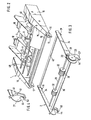
- a separation unit 1 contains the organs necessary for the individual removal of paper sheets from a supply stack and for the transport thereof to the platen roller of an office machine, in particular a typewriter or printer.
- a stack 4 of paper sheets is placed on the two pivotally mounted, inclined rockers 5 and abuts with the front edge against a stop 7.
- the top sheet of the stack 4 is under the pressure of a spring 31 frictionally against two rotatable separating rollers 6, which on one common drive shaft 12 sit.
- This drive shaft 12 is driven by a gear 10 through a gear 14 and a toothed belt 9.
- the lateral drive elements are each covered by a cover 16. From the vertical side walls 15 of the singling unit 1, a tab protrudes downwards at the front and bottom, which contains a recess in the form of a suspension fork 17 opening towards the front.
- the separating assembly 1 is placed on an intermediate frame 2, which is usually longer, the suspension forks 17 being suspended in a rod 36 or shaft 26 of the intermediate frame 2.
- the shaft 26 associated with the intermediate frame 2 is rigidly connected on the outside of the one side plate 24 to a gear 28 which engages in a larger spur gear 29.
- the intermediate frame 2 is placed together with the singling unit 1 on an office machine 3, the opening 44 (FIG. 4) engaging with the shaft collar 45 of the platen roller 42 of the office machine 3.
- a feather Loaded lever 46 with locking hook 50 engages behind the shaft collar 45 and thereby brings about a releasable connection with the office machine 3.
- the office machine 3 contains a print head 33 (FIG. 7) arranged in front of the platen roller 42, such as a ball head or type wheel.
- On the underside of the platen roller there is a customary paper baffle 35 provided with pressure rollers 37.
- the fork 27 with the opening 44 for engaging in the shaft collar 45 or in separate hanging means of the office machine can be designed differently depending on the make of the machine.
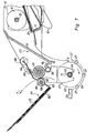
- the clutch gear 43 which is connected to the shaft 45 of the platen roller 42 in a rotationally fixed manner, engages with the gear wheel 29 of the intermediate frame 2, so that every rotational movement of the platen roller 42 is transmitted to the intermediate frame and to the separating assembly. This is done by the gear 29, the gear 28, the pinion 30 of the intermediate frame 2, the gear 10, the gear 14 and via the gear, not shown, on the separating rollers 6.
- the platen roller 42 is driven by an electric motor installed in the office machine which executes rotary movements according to the control logic and the input impulses. For manual rotation, the platen roller 42 is provided on the outside with a handwheel 49.
- the labeled sheet is gripped between the ejection rollers 32 and the leaf springs 54 (FIG. 6) and deposited in a storage compartment 22 to form a stack 25.
- This storage compartment 22 is formed by an obliquely rearwardly extending support wall 8 and a lower obliquely forwardly extending stop rail 19.
- the ejection roller 32 is located directly and immediately in front of the support wall 8.
- the distance between the ejection rollers 32 and the support wall 8 is smaller than the diameter the ejection rollers 32.
- the corner of the storage compartment 22 lies below the center line of the ejection rollers 32.
- the ejection rollers 32 are thus the only transport elements for the inscribed sheets between the platen roller 42 and the storage compartment 22.
- baffle plate 13 in which leaf springs 54 are held, which press the leaves slightly from above in the direction of the ejection rollers 32.
- the baffle plate 13 is laterally held by two rotatable suspension disks 66, each provided with a slot, in the separating unit and supported by guide strips 68.
- FIG. 7 shows an embodiment variant in which the difference compared to the embodiment shown in FIG. 6 is that the storage compartment 61 is inclined forward - that is, opposite to the storage compartment 22.
- This Storage compartment 61 for the sheets coming from the platen roller 42 contains an oblique main support 62 and at the bottom an angled stop support 63 for receiving the stack 25.
- This storage compartment 61 is detachably connected to the separating assembly by means of fastening arms 64 via hanging disks 66.
- the support is provided by guide strips 68 on the side walls 15. With the fastening arms 64 or with the stop support 63, a number of pressure rollers 56 corresponding to the number of ejection rollers 32 are rotatably held.
- the weight of the storage compartment 61 and the stack 25 results in a slight pressing force of the pressure rollers 56 against the ejection rollers 32.
- the lower corner of the storage compartment 61 is located below the shaft 26.
- This storage compartment can thus be selected can be used instead of the deflection plate 13 in the same fastening members 66, 68. This makes it possible to optionally place the sheets on the storage compartment 22 or 61.
- the storage compartment 61 can be made of wire, sheet metal or plastic and could also be mounted laterally in the intermediate frame.
- This device is as follows: From a stack of sheets 4, which is placed on the rockers 5, a certain rotational movement of the platen roller 42 in the direction of the arrow G (FIG. 7) can be pulled off by a control logic of the machine.
- the two separating rollers 6 rotate in the direction of arrow A and thereby transport the top sheet moving past the corner separator 21 into the feed nip 57 of the platen roller 42.
- the sheet is then labeled in a manner known per se by the platen head 33 and reaches the front of the platen roller 42 for output.
- the leaf movement is shown in Fig. 7 by arrows E, F.
- the sheet is then deposited either on the stack 22 or on the stack 61.
- the intermediate frame 2 can be made to be of any length, so that it can be easily adapted to typewriters or printers of different dimensions, without changes to the separating assembly 1 being necessary. As a result, the same separating assembly 1 can be used for different makes and only an easier implementation of the intermediate frame 2 is required.
- this spur gear can be designed as a double gear with a different tooth module.
- leaf springs 54 there could also be spring-loaded pressure rollers, which bear against the ejection rollers 32 and between which the labeled leaves are passed.
- Another variant consists in that the labeled sheets are passed through the gap 37 between the rod 36 and the ejection rollers 32.
- the rod 36 is designed as a loosely rotatable shaft and, if need be, provided with a friction-increasing coating or roller.
- the direction of rotation of the ejection rollers 32 must be changed and the shape of the deflection plate 13 must be adapted accordingly so that the inscribed sheets emanating from the platen roller are directed into the gap 37.
- the gears can also be replaced by friction wheels.
Landscapes
- Sheets, Magazines, And Separation Thereof (AREA)
- Handling Of Cut Paper (AREA)
- Delivering By Means Of Belts And Rollers (AREA)
- Pile Receivers (AREA)
- Feeding Of Articles By Means Other Than Belts Or Rollers (AREA)
Applications Claiming Priority (2)
| Application Number | Priority Date | Filing Date | Title |
|---|---|---|---|
| CH6129/83A CH661478A5 (de) | 1983-11-15 | 1983-11-15 | Vorrichtung zum vereinzeln und zum einzug von blaettern in eine bueromaschine. |
| CH6129/83 | 1983-11-15 |
Publications (2)
| Publication Number | Publication Date |
|---|---|
| EP0142472A2 true EP0142472A2 (fr) | 1985-05-22 |
| EP0142472A3 EP0142472A3 (fr) | 1987-12-16 |
Family
ID=4304737
Family Applications (1)
| Application Number | Title | Priority Date | Filing Date |
|---|---|---|---|
| EP84810540A Withdrawn EP0142472A3 (fr) | 1983-11-15 | 1984-11-07 | Dispositif pour séparer et alimenter des feuilles dans une machine de bureau |
Country Status (6)
| Country | Link |
|---|---|
| US (1) | US4565360A (fr) |
| EP (1) | EP0142472A3 (fr) |
| JP (1) | JPS60122658A (fr) |
| BR (1) | BR8405731A (fr) |
| CA (1) | CA1221993A (fr) |
| CH (1) | CH661478A5 (fr) |
Cited By (4)
| Publication number | Priority date | Publication date | Assignee | Title |
|---|---|---|---|---|
| EP0303556A1 (fr) * | 1987-08-11 | 1989-02-15 | MANNESMANN Aktiengesellschaft | Dispositif de guidage de papier pour machines de bureau, notamment pour imprimantes à matrice |
| EP0230548A3 (fr) * | 1986-01-28 | 1989-07-26 | Ziyad, Incorporated | Panier de papier pour un dispositif d'imprimeur |
| USD304956S (en) | 1985-11-28 | 1989-12-05 | Canon Kabushiki Kaisha | Paper feeder for printer |
| EP0368685A3 (fr) * | 1988-11-11 | 1991-01-09 | Brother Kogyo Kabushiki Kaisha | Dispositif d'avance et de réception de feuilles utilisé avec une imprimante |
Families Citing this family (22)
| Publication number | Priority date | Publication date | Assignee | Title |
|---|---|---|---|---|
| USD287509S (en) | 1984-06-04 | 1986-12-30 | Canon Kabushiki Kaisha | Paper feeder for printer |
| JPH058276Y2 (fr) * | 1986-01-27 | 1993-03-02 | ||
| DE3723722A1 (de) * | 1986-07-18 | 1988-01-28 | Canon Kk | Aufzeichnungsgeraet mit einer formatblattzufuehreinrichtung |
| USD318875S (en) | 1987-06-19 | 1991-08-06 | Nec Corporation | Sheet feeder for computer output printers |
| DE3925162A1 (de) * | 1988-08-17 | 1990-02-22 | Daiwa Seiko Inc | Druckmaschine |
| WO1990002656A1 (fr) * | 1988-09-08 | 1990-03-22 | Siemens Aktiengesellschaft | Dispositif pour empiler des feuilles dans une imprimante |
| JP2691918B2 (ja) * | 1988-09-28 | 1997-12-17 | 株式会社リコー | 画像形成装置における給紙装置 |
| USD321712S (en) | 1989-03-07 | 1991-11-19 | Mita Industrial Co., Ltd. | Sheet feeder |
| US5291224A (en) * | 1989-10-27 | 1994-03-01 | Canon Kabushiki Kaisha | Sheet feeding apparatus using pairs of spur rollers |
| EP0446840B1 (fr) * | 1990-03-12 | 1996-10-09 | Canon Kabushiki Kaisha | Appareil automatique d'alimentation de papier |
| GB2259909B (en) * | 1991-09-11 | 1995-10-18 | Xerox Corp | Sheet feed apparatus |
| JP3293359B2 (ja) * | 1994-09-03 | 2002-06-17 | オムロン株式会社 | 紙葉類保持装置 |
| US5938190A (en) * | 1996-05-31 | 1999-08-17 | Lexmark International, Inc. | Specialty media feed guide and sheet feeding apparatus using same |
| KR100211795B1 (ko) * | 1996-11-08 | 1999-08-02 | 윤종용 | 레이저 빔 프린터의 보조 급지 장치용 구동장치 |
| JP3520169B2 (ja) * | 1997-03-04 | 2004-04-19 | 株式会社リコー | 画像形成装置 |
| JP3681905B2 (ja) | 1997-11-11 | 2005-08-10 | 株式会社リコー | シート収納装置 |
| US20030041756A1 (en) * | 2001-08-29 | 2003-03-06 | Andreas Detmers | Rotary printing press |
| US7641190B2 (en) * | 2002-07-12 | 2010-01-05 | Oki Data Corporation | Medium tray and image recording apparatus using the same |
| US20050082740A1 (en) * | 2003-10-21 | 2005-04-21 | Stevens Kenneth A. | High capacity document sheet processor |
| US7025345B2 (en) * | 2004-01-08 | 2006-04-11 | Xerox Corporation | Replacement method and assembly for paper pick rollers |
| JP4419733B2 (ja) * | 2004-07-16 | 2010-02-24 | ブラザー工業株式会社 | 画像形成装置 |
| US7784782B2 (en) * | 2007-10-02 | 2010-08-31 | Lexmark International, Inc. | Automatic sheet feed extender for paperfeed modularity |
Family Cites Families (7)
| Publication number | Priority date | Publication date | Assignee | Title |
|---|---|---|---|---|
| US4089402A (en) * | 1976-07-01 | 1978-05-16 | Hy Grip Products Co. | Sheet feeding mechanism for an automatic typewriter |
| US4222557A (en) * | 1978-05-16 | 1980-09-16 | Wang Laboratories, Inc. | Printer feeding and stacking |
| US4326815A (en) * | 1980-01-21 | 1982-04-27 | Ziyad Incorporated | Paper feeding apparatus and method for printing apparatus |
| US4319282A (en) * | 1980-02-11 | 1982-03-09 | Exxon Research & Engineering Co. | Facsimile method and apparatus with sheet feeding |
| US4371276A (en) * | 1980-07-31 | 1983-02-01 | Xerox Corporation | Sheet stacking output tray |
| CH651808A5 (de) * | 1981-07-30 | 1985-10-15 | Albert Rutishauser | Transportvorrichtung fuer blattfoermige aufzeichnungstraeger. |
| SE444536B (sv) * | 1982-03-08 | 1986-04-21 | Facit Ab | Pappersmatningsanordning vid en med pappersmagasin forsedd skrivare, skrivmaskin eller liknande kontorsmaskin |
-
1983
- 1983-11-15 CH CH6129/83A patent/CH661478A5/de not_active IP Right Cessation
-
1984
- 1984-01-30 US US06/575,183 patent/US4565360A/en not_active Expired - Fee Related
- 1984-11-01 CA CA000466859A patent/CA1221993A/fr not_active Expired
- 1984-11-07 EP EP84810540A patent/EP0142472A3/fr not_active Withdrawn
- 1984-11-09 BR BR8405731A patent/BR8405731A/pt unknown
- 1984-11-13 JP JP59237713A patent/JPS60122658A/ja active Pending
Cited By (7)
| Publication number | Priority date | Publication date | Assignee | Title |
|---|---|---|---|---|
| USD304956S (en) | 1985-11-28 | 1989-12-05 | Canon Kabushiki Kaisha | Paper feeder for printer |
| EP0230548A3 (fr) * | 1986-01-28 | 1989-07-26 | Ziyad, Incorporated | Panier de papier pour un dispositif d'imprimeur |
| EP0303556A1 (fr) * | 1987-08-11 | 1989-02-15 | MANNESMANN Aktiengesellschaft | Dispositif de guidage de papier pour machines de bureau, notamment pour imprimantes à matrice |
| DE3727070A1 (de) * | 1987-08-11 | 1989-02-23 | Mannesmann Ag | Papierfuehrungsvorrichtung fuer bueromaschinen, insbesondere fuer matrixdrucker |
| US4995747A (en) * | 1987-08-11 | 1991-02-26 | Mannesmann Aktiengesellschaft | Paper stacking apparatus for office machines |
| EP0368685A3 (fr) * | 1988-11-11 | 1991-01-09 | Brother Kogyo Kabushiki Kaisha | Dispositif d'avance et de réception de feuilles utilisé avec une imprimante |
| US5073055A (en) * | 1988-11-11 | 1991-12-17 | Brother Kogyo Kabushiki Kaisha | Sheet-feed/sheet-receiving unit used in combination with printer |
Also Published As
| Publication number | Publication date |
|---|---|
| JPS60122658A (ja) | 1985-07-01 |
| EP0142472A3 (fr) | 1987-12-16 |
| US4565360A (en) | 1986-01-21 |
| BR8405731A (pt) | 1985-09-17 |
| CA1221993A (fr) | 1987-05-19 |
| CH661478A5 (de) | 1987-07-31 |
Similar Documents
| Publication | Publication Date | Title |
|---|---|---|
| EP0142472A2 (fr) | Dispositif pour séparer et alimenter des feuilles dans une machine de bureau | |
| EP0106801B2 (fr) | Dispositif pour alimenter une machine de bureau en feuilles individuelles | |
| DE2854695C2 (de) | Transportvorrichtung für blattförmige Aufzeichnungsträger | |
| DE4330798C2 (de) | Drucker | |
| DE3107768C2 (de) | Vorrichtung zur Aufnahme einzeln zugeführter Blätter | |
| DE60222834T2 (de) | Auswechselbares Rollerdrehgestell für einen Dokumentenzuführapparat | |
| DE69120565T2 (de) | Papier-Rollen-Zuführer für Kopierer oder FAX-Gerät | |
| DE2711173B2 (de) | Einrichtung an einer schreibenden oder druckenden Büromaschine zum Beschicken derselben mit Blättern | |
| DE4042358A1 (de) | Sortiergeraet zur ablage von blattfoermigen aufzeichnungstraegern | |
| CH598105A5 (fr) | ||
| CH645741A5 (de) | Aufzeichnungsmaterialzufuhrvorrichtung. | |
| DE2946960C2 (de) | Blattzuführeinrichtung | |
| EP2597624B1 (fr) | Machine d'affranchissement et/ou à imprimer les adresses | |
| DE3527495C2 (de) | Blattzuführvorrichtung zum Zuführen von Blättern einzeln von einem Stapel zu einem Verarbeitungsgerät | |
| DE3811988C2 (fr) | ||
| DE3844693C2 (fr) | ||
| DE3806552A1 (de) | Vorrichtung zum vorwaerts- und rueckwaertstransport von aufzeichnungspapier in einem drucker | |
| EP0978466B1 (fr) | Appareil pour la séparation de documents | |
| DE3007838C2 (de) | Vorrichtung für Druckeinrichtungen zur Ablage von blattförmigen Aufzeichnungsträgern | |
| EP0461118B1 (fr) | Dispositif de transport de feuilles dans une imprimante a l'encre | |
| DE3343170A1 (de) | Vorrichtung zur zufuehrung von zu beschriftendem papier in eine schreib- oder druckmaschine | |
| EP0303556B1 (fr) | Dispositif de guidage de papier pour machines de bureau, notamment pour imprimantes à matrice | |
| DE3512068A1 (de) | Einrichtung zum automatischen zufuehren und abgeben von papierblaettern fuer einen buerodrucker | |
| DE3121661A1 (de) | Einzelblattzufuehrvorrichtung zur schreibwalze einer bueromaschine | |
| DE4345333C2 (de) | Tintenstrahldrucker |
Legal Events
| Date | Code | Title | Description |
|---|---|---|---|
| PUAI | Public reference made under article 153(3) epc to a published international application that has entered the european phase |
Free format text: ORIGINAL CODE: 0009012 |
|
| AK | Designated contracting states |
Designated state(s): CH DE FR GB IT LI NL SE |
|
| RTI1 | Title (correction) | ||
| PUAL | Search report despatched |
Free format text: ORIGINAL CODE: 0009013 |
|
| AK | Designated contracting states |
Kind code of ref document: A3 Designated state(s): CH DE FR GB IT LI NL SE |
|
| 17P | Request for examination filed |
Effective date: 19880609 |
|
| 17Q | First examination report despatched |
Effective date: 19881202 |
|
| STAA | Information on the status of an ep patent application or granted ep patent |
Free format text: STATUS: THE APPLICATION IS DEEMED TO BE WITHDRAWN |
|
| 18D | Application deemed to be withdrawn |
Effective date: 19890529 |