EP0142817B1 - Méthode de test pour système d'allumage de moteur à combustion interne - Google Patents
Méthode de test pour système d'allumage de moteur à combustion interne Download PDFInfo
- Publication number
- EP0142817B1 EP0142817B1 EP84113722A EP84113722A EP0142817B1 EP 0142817 B1 EP0142817 B1 EP 0142817B1 EP 84113722 A EP84113722 A EP 84113722A EP 84113722 A EP84113722 A EP 84113722A EP 0142817 B1 EP0142817 B1 EP 0142817B1
- Authority
- EP
- European Patent Office
- Prior art keywords
- ignition
- spark plug
- combustion engine
- operating state
- internal combustion
- Prior art date
- Legal status (The legal status is an assumption and is not a legal conclusion. Google has not performed a legal analysis and makes no representation as to the accuracy of the status listed.)
- Expired - Lifetime
Links
- 238000002485 combustion reaction Methods 0.000 title claims description 13
- 238000010998 test method Methods 0.000 title claims description 8
- 238000012360 testing method Methods 0.000 claims description 17
- 238000000034 method Methods 0.000 claims description 8
- 230000001960 triggered effect Effects 0.000 claims description 6
- 239000000446 fuel Substances 0.000 claims description 4
- 238000012423 maintenance Methods 0.000 claims description 4
- 238000010586 diagram Methods 0.000 description 3
- 230000006698 induction Effects 0.000 description 3
- 239000000203 mixture Substances 0.000 description 2
- 238000012935 Averaging Methods 0.000 description 1
- 238000001514 detection method Methods 0.000 description 1
- 238000011143 downstream manufacturing Methods 0.000 description 1
- 230000006870 function Effects 0.000 description 1
- 238000005259 measurement Methods 0.000 description 1
Images
Classifications
-
- F—MECHANICAL ENGINEERING; LIGHTING; HEATING; WEAPONS; BLASTING
- F02—COMBUSTION ENGINES; HOT-GAS OR COMBUSTION-PRODUCT ENGINE PLANTS
- F02P—IGNITION, OTHER THAN COMPRESSION IGNITION, FOR INTERNAL-COMBUSTION ENGINES; TESTING OF IGNITION TIMING IN COMPRESSION-IGNITION ENGINES
- F02P17/00—Testing of ignition installations, e.g. in combination with adjusting; Testing of ignition timing in compression-ignition engines
- F02P17/12—Testing characteristics of the spark, ignition voltage or current
Definitions
- the invention relates to a test method for ignition systems of internal combustion engines in motor vehicles.
- the ignition system is checked for proper function.
- the characteristic value of the ignition voltage signal for example the maximum value
- the ignition voltage signal can also be compared with a corresponding signal from another cylinder or the ignition voltage signal of all cylinders. If these signals are the same as each other, the ignition device is OK, but if one or more of these signals deviate greatly from one another, the ignition system is likely to be faulty. However, this only allows a relatively rough statement about the condition of the ignition system.
- the invention has for its object to provide a test method of the type mentioned, which provides precise information about the element determining the condition of the ignition system and thus about the ignition system as such.
- the invention solves this problem in that, in order to test the electrode spacing of a spark plug, the desired signal is taken at the beginning of a test period and in an operating state which is at least approximately the same as the current operating state at the time of the test.
- the invention initially assumes that the condition of the ignition system is determined almost exclusively by the spark plugs which are subject to wear, since further wear parts are not present, in particular in the case of contactless ignition systems.
- Known test methods for spark plugs infer the state of the spark plugs from the level of the ignition voltage on the secondary side (cf. DE-OS 23 22 834, DE-OS 26 08 707 and US Pat. No. 2,430,069).
- the invention offers two major advantages. On the one hand, the test is carried out on the basis of the ignition voltage signal on the primary side, the amplitudes of which are far lower than the signal on the secondary side.
- the test is carried out without intervention in the ignition system, while in the known spark plug test methods the secondary-side ignition voltage signal is supplied externally with the aid of separate adapters.
- the invention thus makes it possible to continuously determine the wear of the spark plugs without intervention in the ignition system and to provide a relative statement about the condition of the spark plugs at any time during operation.
- This operating state can be, for example, the overrun operation of the internal combustion engine. Is it an internal combustion engine with so-called overrun fuel cutoff, i.e. the interruption of the fuel supply in overrun mode, the influence of the fuel-air mixture on the test result is completely excluded.
- the switch available for the detection of overrun operation for example on the throttle valve, can also be used to initiate the test method. But even without overrun cut-off, overrun mode offers the possibility to carry out the test of the spark plug under approximately the same and constant test conditions. For this purpose, it is then still necessary to take into account the speed or the speed curve of the internal combustion engine.
- the test period over which the entire test of the spark plug should extend can be chosen freely and with any starting point. In contrast, there are advantages to starting the test period with the start-up of the spark plug. This ensures that the spark plugs are in order at the beginning of the test period and that the changes in the primary-side ignition voltage signal are related to the total wear of the spark plug.
- the start of the test period can be determined arbitrarily or with the aid of a signal triggered automatically when maintenance is carried out.
- the prerequisite for the latter is that it involves maintenance in which the spark plugs are routinely replaced.
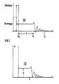
- Diagrams A and B shown in FIG. 1 show the primary-side ignition voltage signal of a spark plug with a normal (A) and too large (B) electrode spacing. It can be clearly seen that the two ignition voltage signals differ essentially in three points. Firstly, the greater the electrode spacing, the greater the maximum amplitude (a). Secondly, the larger the electrode spacing, the greater the internal voltage (b), and thirdly, the shorter the electrode spacing, the longer the burning time (d).
- the two diagrams A and B show the course of the ignition voltage signal in at least approximately the same operating state of the internal combustion engine, in the present case in overrun mode with the fuel supply switched off and the same number of engine revolutions.
- the reason for the different course of the ignition voltage signals on the primary side is a correspondingly different course of the ignition voltage, not shown, on the secondary side signals. These, in turn, have their original ash in the different electrical conditions, which depend on the electrode spacing, for the ignition spark between the two electrodes of the spark plug during the burning period d.
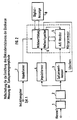
- the circuit shown in FIG. 2 serves to determine the ignition voltage amplitude a.
- the ignition signal between an induction transmitter, not shown, and an ignition coil, also not shown is taken off (so-called terminal 1 signal) and fed via an amplitude attenuator 1 to a low-pass filter 2, a peak value meter 3 and a pulse shaper 4.
- the output signal of the peak value meter 3 is digitized in an analog / digital converter 5 and stored in a measurement value memory 6. This is triggered by the signal from an induction transmitter (not shown) with a pulse shaper 7 connected downstream.
- the digital values of ignition voltage amplitudes for the spark plug to be tested are stored and averaged in the measured value memory 6.
- the speed is detected with the aid of the speed-proportional signals supplied by the induction transmitter to the pulse shaper.
- the constant operating state is obtained with the aid of this rotational speed and an additional signal from a switch which is arranged, for example, on the throttle valve of the internal combustion engine and which is actuated when the throttle valve is closed.
- the ignition voltage amplitude is thus determined for this operating state with the aid of averaging.
- the test method includes determining the ignition voltage amplitude in the manner described when the spark plug is started up. A signal routinely triggered when maintenance is carried out is used for this purpose. With this setpoint value obtained with the aid of the spark plug to be tested, the respective ignition voltage amplitudes are now determined in the same way, for example when the same operating conditions of the internal combustion engine are present, and compared with the setpoint value in a downstream processing stage 8. If the current value of the ignition voltage amplitude deviates from this target value by a predetermined amount, a warning signal is generated in a known manner or the degree of wear of the spark plug is indicated in the context of a service interval display.
Landscapes
- Engineering & Computer Science (AREA)
- Chemical & Material Sciences (AREA)
- Combustion & Propulsion (AREA)
- Mechanical Engineering (AREA)
- General Engineering & Computer Science (AREA)
- Ignition Installations For Internal Combustion Engines (AREA)
Claims (6)
Applications Claiming Priority (2)
| Application Number | Priority Date | Filing Date | Title |
|---|---|---|---|
| DE3341880 | 1983-11-19 | ||
| DE19833341880 DE3341880A1 (de) | 1983-11-19 | 1983-11-19 | Pruefverfahren fuer zuendanlagen von brennkraftmaschinen in kraftfahrzeugen |
Publications (3)
| Publication Number | Publication Date |
|---|---|
| EP0142817A2 EP0142817A2 (fr) | 1985-05-29 |
| EP0142817A3 EP0142817A3 (en) | 1986-03-26 |
| EP0142817B1 true EP0142817B1 (fr) | 1991-01-16 |
Family
ID=6214752
Family Applications (1)
| Application Number | Title | Priority Date | Filing Date |
|---|---|---|---|
| EP84113722A Expired - Lifetime EP0142817B1 (fr) | 1983-11-19 | 1984-11-14 | Méthode de test pour système d'allumage de moteur à combustion interne |
Country Status (4)
| Country | Link |
|---|---|
| US (1) | US4684896A (fr) |
| EP (1) | EP0142817B1 (fr) |
| JP (1) | JPS60119377A (fr) |
| DE (2) | DE3341880A1 (fr) |
Families Citing this family (44)
| Publication number | Priority date | Publication date | Assignee | Title |
|---|---|---|---|---|
| US4825167A (en) * | 1987-11-02 | 1989-04-25 | General Motors Corporation | Spark plug testing under dynamic load |
| KR960012145B1 (ko) * | 1988-04-02 | 1996-09-16 | 로베르트 보쉬 게엠베하 | 스파크 점화 내연 기관의 연소를 모니터하는 방법 및 그 장치 |
| US5155437A (en) * | 1990-07-26 | 1992-10-13 | Unison Industries Limited Partnership | Diagnostic device for gas turbine ignition system |
| US5523691A (en) * | 1990-07-26 | 1996-06-04 | Unison Industries Limited Partnership | Diagnostic device for gas turbine ignition system |
| US5370099A (en) * | 1990-08-24 | 1994-12-06 | Robert Bosch Gmbh | Ignition system for internal combustion engines |
| DE4026723A1 (de) * | 1990-08-24 | 1992-02-27 | Bosch Gmbh Robert | Zuendanlage fuer brennkraftmaschinen |
| JP2678986B2 (ja) * | 1991-03-07 | 1997-11-19 | 本田技研工業株式会社 | 内燃機関の失火検出装置 |
| US5283527A (en) * | 1991-06-28 | 1994-02-01 | Ford Motor Company | Methods and apparatus for detecting short circuited secondary coil winding via monitoring primary coil winding |
| FR2680836A1 (fr) * | 1991-08-29 | 1993-03-05 | Renault | Procede et dispositif de surveillance de l'ecartement des electrodes d'une bougie. |
| US5194813A (en) * | 1991-09-16 | 1993-03-16 | Hannah Kenneth H | Spark ignition analyzer |
| FR2687255B1 (fr) * | 1992-02-07 | 1994-03-25 | Renault Regie Nale Usines | Procede d'estimation de l'etat d'usure d'une bougie. |
| US5208540A (en) * | 1992-02-28 | 1993-05-04 | Coltec Industries Inc. | Ignition performance monitor and monitoring method for capacitive discharge ignition systems |
| FR2712934B1 (fr) * | 1993-11-22 | 1996-01-26 | Marelli Autronica | Procédé et dispositif d'allumage à bobine, pour moteur à allumage commandé. |
| AU2297495A (en) * | 1994-04-19 | 1995-11-10 | Gas Research Institute | Breakdown voltage measurement apparatus and method |
| WO1996015366A1 (fr) * | 1994-11-14 | 1996-05-23 | Kayser William M | Appareil d'analyse pour moteurs equipes de bougies d'allumage |
| US5635841A (en) * | 1995-03-31 | 1997-06-03 | Innova Electronic Corporation | Electronic ignition control module test system |
| US5606118A (en) * | 1995-09-05 | 1997-02-25 | Ford Motor Company | System and method for detecting misfire in an internal combustion engine |
| US5997360A (en) * | 1997-10-14 | 1999-12-07 | Gen-Kuong; Fernando Francisco | Aircraft equipment configuration identification interface |
| US6044700A (en) * | 1997-10-14 | 2000-04-04 | Endevco Corporation | Aircraft equipment configuration identification interface guide |
| US6006156A (en) * | 1997-12-11 | 1999-12-21 | Cummins Engine Company, Inc. | Apparatus and method for diagnosing and controlling an ignition system of an internal combustion engine |
| US6408242B1 (en) | 1997-12-11 | 2002-06-18 | Cummins, Inc. | Apparatus and method for diagnosing and controlling an ignition system of an internal combustion engine |
| DE19756336C1 (de) * | 1997-12-18 | 1999-04-01 | Daimler Benz Ag | Verfahren und Vorrichtung zur Prüfung der Kompression sowie der Zündanlage einer Verbrennungskraftmaschine |
| US6392315B1 (en) * | 1999-04-05 | 2002-05-21 | Delphi Technologies, Inc. | Compensation circuit for an automotive ignition sensing system |
| US7376497B2 (en) * | 2001-09-21 | 2008-05-20 | Innova Electronics Corporation | Use of automotive diagnostics console to diagnose vehicle |
| KR20030025731A (ko) * | 2001-09-24 | 2003-03-29 | 현대자동차주식회사 | 엔진에 장착된 상태의 스파크 플러그 간극 점검 방법 |
| US20050182535A1 (en) * | 2004-02-17 | 2005-08-18 | David Huang | Device and method for identifying a specific communication protocol used in an on-board diagnostic tool |
| US7603293B2 (en) | 2005-06-24 | 2009-10-13 | Innova Electronics Corporation | Method of providing diagnostic information in connection with the sale of pre-owned vehicles |
| US8024083B2 (en) * | 2005-06-30 | 2011-09-20 | Chenn Ieon C | Cellphone based vehicle diagnostic system |
| US8068951B2 (en) * | 2005-06-24 | 2011-11-29 | Chen Ieon C | Vehicle diagnostic system |
| US20060293811A1 (en) * | 2005-06-24 | 2006-12-28 | Keith Andreasen | Automotive data logger |
| US8019503B2 (en) * | 2007-06-28 | 2011-09-13 | Innova Electronics Corp | Automotive diagnostic and remedial process |
| US9117319B2 (en) * | 2005-06-30 | 2015-08-25 | Innova Electronics, Inc. | Handheld automotive diagnostic tool with VIN decoder and communication system |
| US20070143000A1 (en) * | 2005-12-16 | 2007-06-21 | Trevor Scott Bryant | Wireless Spark Energy Indicator |
| DE102006011886A1 (de) * | 2006-03-15 | 2007-09-20 | Bayerische Motoren Werke Ag | Vorrichtung und Verfahren zur Bestimmung des Verschleiß einer Zündkerze einer Brennkraftmaschine |
| US9026400B2 (en) | 2007-06-28 | 2015-05-05 | Innova Electonics, Inc. | Diagnostic process for home electronic devices |
| US8370018B2 (en) * | 2007-06-28 | 2013-02-05 | Innova Electronics, Inc. | Automotive diagnostic process |
| MX2010003797A (es) * | 2007-10-09 | 2011-02-03 | Flextronics Automotive Inc | Sonda de sensor de bujia que utiliza pcb como antena. |
| US8306687B2 (en) * | 2009-11-10 | 2012-11-06 | Innova Electronics, Inc. | Method of diagnosing a vehicle having diagnostic data |
| DE102011005651A1 (de) * | 2011-03-16 | 2012-09-20 | Man Diesel & Turbo Se | Verfahren zur Bestimmung des Verschleißes von Elektroden einer Zündkerze und Vorrichtungen hierzu |
| CN103541852A (zh) * | 2013-10-08 | 2014-01-29 | 成都泛华航空仪表电器有限公司 | 全自动化点火器试验系统 |
| DE102016218662B4 (de) | 2016-09-28 | 2022-01-13 | Bayerische Motoren Werke Aktiengesellschaft | Testen einer elektrischen Fahrzeug-Komponente |
| US11574510B2 (en) | 2020-03-30 | 2023-02-07 | Innova Electronics Corporation | Multi-functional automotive diagnostic tablet with interchangeable function-specific cartridges |
| US11967189B2 (en) | 2020-04-20 | 2024-04-23 | Innova Electronics Corporation | Router for communicating vehicle data to a vehicle resource |
| US11651628B2 (en) | 2020-04-20 | 2023-05-16 | Innova Electronics Corporation | Router for vehicle diagnostic system |
Citations (1)
| Publication number | Priority date | Publication date | Assignee | Title |
|---|---|---|---|---|
| DE2343895A1 (de) * | 1973-08-31 | 1975-03-13 | Bosch Gmbh Robert | Verfahren und einrichtung zur ueberpruefung der zuendanlage von brennkraftmaschinen |
Family Cites Families (12)
| Publication number | Priority date | Publication date | Assignee | Title |
|---|---|---|---|---|
| US2430069A (en) * | 1944-12-02 | 1947-11-04 | Gilbert & Barker Mfg Co | Apparatus for testing spark plugs |
| DE2322834A1 (de) * | 1973-05-07 | 1974-11-28 | Nicholas George Festos | Tragbares pruefgeraet fuer zuendkerzen |
| DE2608707A1 (de) * | 1976-03-03 | 1977-09-08 | Daimler Benz Ag | Verfahren und messgeraet zur messung des abstands zweier elektroden |
| US4053823A (en) * | 1976-04-22 | 1977-10-11 | Adamian Michael R | Ignition arc monitor circuit |
| DE2752244A1 (de) * | 1977-11-23 | 1979-06-07 | Baum Elektrophysik Gmbh | Verfahren und vorrichtung zum pruefen elektrischer zuendanlagen von otto-motoren |
| DE2759155C2 (de) * | 1977-12-31 | 1986-04-03 | Robert Bosch Gmbh, 7000 Stuttgart | Schaltungsanordnung zur Erfassung der Funkendauer in Zündeinrichtungen für Brennkraftmaschinen |
| DE2811573A1 (de) * | 1978-03-17 | 1979-09-27 | Bosch Gmbh Robert | Einrichtung zur ueberpruefung einer zuendanlage fuer brennkraftmaschinen |
| JPS56115866A (en) * | 1980-02-15 | 1981-09-11 | Nippon Denso Co Ltd | Detector of abnormality in ignition signal for internal combustion engine |
| US4394742A (en) * | 1980-10-31 | 1983-07-19 | Fmc Corporation | Engine generated waveform analyzer |
| DE3151415C2 (de) * | 1981-12-24 | 1986-11-20 | Daimler-Benz Ag, 7000 Stuttgart | Verfahren zur Messung des Elektrodenabstandes der Zündkerzen eines Kraftfahrzeuges und Gerät zur Durchführung des Verfahrens |
| US4449100A (en) * | 1982-04-05 | 1984-05-15 | Ford Motor Company | Ignition system tester |
| JPS5920866A (ja) * | 1982-07-27 | 1984-02-02 | Toyota Central Res & Dev Lab Inc | 多気筒エンジンの点火プラグ検査装置 |
-
1983
- 1983-11-19 DE DE19833341880 patent/DE3341880A1/de active Granted
-
1984
- 1984-11-13 JP JP59237710A patent/JPS60119377A/ja active Pending
- 1984-11-14 EP EP84113722A patent/EP0142817B1/fr not_active Expired - Lifetime
- 1984-11-14 DE DE8484113722T patent/DE3483952D1/de not_active Expired - Lifetime
- 1984-11-16 US US06/671,914 patent/US4684896A/en not_active Expired - Fee Related
Patent Citations (1)
| Publication number | Priority date | Publication date | Assignee | Title |
|---|---|---|---|---|
| DE2343895A1 (de) * | 1973-08-31 | 1975-03-13 | Bosch Gmbh Robert | Verfahren und einrichtung zur ueberpruefung der zuendanlage von brennkraftmaschinen |
Also Published As
| Publication number | Publication date |
|---|---|
| EP0142817A3 (en) | 1986-03-26 |
| JPS60119377A (ja) | 1985-06-26 |
| DE3341880A1 (de) | 1985-05-30 |
| US4684896A (en) | 1987-08-04 |
| DE3341880C2 (fr) | 1987-10-15 |
| EP0142817A2 (fr) | 1985-05-29 |
| DE3483952D1 (de) | 1991-02-21 |
Similar Documents
| Publication | Publication Date | Title |
|---|---|---|
| EP0142817B1 (fr) | Méthode de test pour système d'allumage de moteur à combustion interne | |
| DE3208587C2 (de) | Einrichtung zur Erkennung von Zündaussetzern | |
| DE4207140C2 (de) | Fehlzündungsdetektorsystem zum Detektieren einer Fehlzündung in einem Verbrennungsmotor | |
| DE3785439T2 (de) | Verfahren und geraet zur feststellung und anzeige von zuendungsanomalien beim betrieb von zuendsystemen von verbrennungsmaschinen, insbesondere fuer mit einem katalysator ausgestattete motorfahrzeuge. | |
| DE4116642C2 (de) | Zündanlage einer Brennkraftmaschine mit einer Überwachungsschaltung zum Erkennen von Zündaussetzern | |
| DE102015203758B4 (de) | Verbrennungsmotor-Steuervorrichtung | |
| DE4126961C2 (de) | Klopfsteuer-Verfahren und Vorrichtung für Verbrennungskraftmaschinen | |
| DE102014217402A1 (de) | Verfahren und Vorrichtung zur Diagnose der Funktion eines Abgassensors | |
| DE2343895A1 (de) | Verfahren und einrichtung zur ueberpruefung der zuendanlage von brennkraftmaschinen | |
| EP0752580B1 (fr) | Circuit de mesure pour courant ionique | |
| DE69720853T2 (de) | Verfahren zur Ermittlung von vorzeitigen Zündungen | |
| EP1222385A1 (fr) | Dispositif et procede d'allumage pour moteur a combustion interne | |
| DE3852390T2 (de) | Einrichtung zur Erkennung von Zündaussetzern bei fremdgezündeten Brennkraftmaschinen. | |
| EP0656096B1 (fr) | Systeme d'allumage pour moteurs a combustion interne comprenant un dispositif de detection des defauts d'allumage par comparaison avec des allumages de reference de la meme bobine d'allumage | |
| DE69331790T2 (de) | Fehlzündungsdetektor mit verschiedenen Methoden bei hoher und niedriger Motorgeschwindigkeit | |
| DE19646917A1 (de) | Vorrichtung zum Erfassen eines Zustands einer Verbrennung in einer Brennkraftmaschine | |
| DE19524499B4 (de) | Zündanlage für eine Brennkraftmaschine | |
| DE19822296A1 (de) | Klopferfassungsvorrichtung für eine Brennkraftmaschine | |
| DE10229848B4 (de) | Feuerungszustandsermittlungssystem für Verbrennungsmotoren | |
| DE4244181C2 (de) | Fehlzündungs-Erfassungssystem für einen Verbrennungsmotor | |
| DE4020986C2 (de) | Elektronisches Zündsystem für eine Brennkraftmaschine | |
| DE102011103427A1 (de) | Verfahren und Vorrichtung zur Klopfregelung | |
| DE3128027A1 (de) | "vorrichtung zum erkennen des klopfens bei brennkraftmaschinen" | |
| DE3338271A1 (de) | Schaltung zur klopferkennung fuer ottomotoren | |
| DE4244804C2 (de) | Fehlzündungserfassungsvorrichtung für eine Brennkraftmaschine |
Legal Events
| Date | Code | Title | Description |
|---|---|---|---|
| PUAI | Public reference made under article 153(3) epc to a published international application that has entered the european phase |
Free format text: ORIGINAL CODE: 0009012 |
|
| AK | Designated contracting states |
Designated state(s): DE FR GB IT SE |
|
| RTI1 | Title (correction) | ||
| PUAL | Search report despatched |
Free format text: ORIGINAL CODE: 0009013 |
|
| AK | Designated contracting states |
Kind code of ref document: A3 Designated state(s): DE FR GB IT SE |
|
| 17P | Request for examination filed |
Effective date: 19861105 |
|
| 17Q | First examination report despatched |
Effective date: 19880608 |
|
| GRAA | (expected) grant |
Free format text: ORIGINAL CODE: 0009210 |
|
| AK | Designated contracting states |
Kind code of ref document: B1 Designated state(s): DE FR GB IT SE |
|
| GBT | Gb: translation of ep patent filed (gb section 77(6)(a)/1977) | ||
| REF | Corresponds to: |
Ref document number: 3483952 Country of ref document: DE Date of ref document: 19910221 |
|
| ET | Fr: translation filed | ||
| ITF | It: translation for a ep patent filed | ||
| PLBE | No opposition filed within time limit |
Free format text: ORIGINAL CODE: 0009261 |
|
| STAA | Information on the status of an ep patent application or granted ep patent |
Free format text: STATUS: NO OPPOSITION FILED WITHIN TIME LIMIT |
|
| 26N | No opposition filed | ||
| PGFP | Annual fee paid to national office [announced via postgrant information from national office to epo] |
Ref country code: SE Payment date: 19921102 Year of fee payment: 9 |
|
| PGFP | Annual fee paid to national office [announced via postgrant information from national office to epo] |
Ref country code: GB Payment date: 19921110 Year of fee payment: 9 |
|
| PGFP | Annual fee paid to national office [announced via postgrant information from national office to epo] |
Ref country code: FR Payment date: 19921127 Year of fee payment: 9 |
|
| PG25 | Lapsed in a contracting state [announced via postgrant information from national office to epo] |
Ref country code: GB Effective date: 19931114 |
|
| PG25 | Lapsed in a contracting state [announced via postgrant information from national office to epo] |
Ref country code: SE Effective date: 19931115 |
|
| GBPC | Gb: european patent ceased through non-payment of renewal fee |
Effective date: 19931114 |
|
| PG25 | Lapsed in a contracting state [announced via postgrant information from national office to epo] |
Ref country code: FR Effective date: 19940729 |
|
| REG | Reference to a national code |
Ref country code: FR Ref legal event code: ST |
|
| EUG | Se: european patent has lapsed |
Ref document number: 84113722.7 Effective date: 19940610 |
|
| PGFP | Annual fee paid to national office [announced via postgrant information from national office to epo] |
Ref country code: DE Payment date: 19981110 Year of fee payment: 15 |
|
| PG25 | Lapsed in a contracting state [announced via postgrant information from national office to epo] |
Ref country code: DE Free format text: LAPSE BECAUSE OF NON-PAYMENT OF DUE FEES Effective date: 20000901 |