EP0142856A2 - Steuereinrichtung des Luft-Kraftstoffverhältnisses in einer Brennkraftmaschine - Google Patents
Steuereinrichtung des Luft-Kraftstoffverhältnisses in einer Brennkraftmaschine Download PDFInfo
- Publication number
- EP0142856A2 EP0142856A2 EP84114026A EP84114026A EP0142856A2 EP 0142856 A2 EP0142856 A2 EP 0142856A2 EP 84114026 A EP84114026 A EP 84114026A EP 84114026 A EP84114026 A EP 84114026A EP 0142856 A2 EP0142856 A2 EP 0142856A2
- Authority
- EP
- European Patent Office
- Prior art keywords
- engine
- fuel
- fuel injection
- throttle
- control
- Prior art date
- Legal status (The legal status is an assumption and is not a legal conclusion. Google has not performed a legal analysis and makes no representation as to the accuracy of the status listed.)
- Withdrawn
Links
Images


Classifications
-
- F—MECHANICAL ENGINEERING; LIGHTING; HEATING; WEAPONS; BLASTING
- F02—COMBUSTION ENGINES; HOT-GAS OR COMBUSTION-PRODUCT ENGINE PLANTS
- F02D—CONTROLLING COMBUSTION ENGINES
- F02D43/00—Conjoint electrical control of two or more functions, e.g. ignition, fuel-air mixture, recirculation, supercharging or exhaust-gas treatment
-
- F—MECHANICAL ENGINEERING; LIGHTING; HEATING; WEAPONS; BLASTING
- F02—COMBUSTION ENGINES; HOT-GAS OR COMBUSTION-PRODUCT ENGINE PLANTS
- F02D—CONTROLLING COMBUSTION ENGINES
- F02D31/00—Use of speed-sensing governors to control combustion engines, not otherwise provided for
- F02D31/001—Electric control of rotation speed
- F02D31/002—Electric control of rotation speed controlling air supply
-
- F—MECHANICAL ENGINEERING; LIGHTING; HEATING; WEAPONS; BLASTING
- F02—COMBUSTION ENGINES; HOT-GAS OR COMBUSTION-PRODUCT ENGINE PLANTS
- F02D—CONTROLLING COMBUSTION ENGINES
- F02D41/00—Electrical control of supply of combustible mixture or its constituents
- F02D41/02—Circuit arrangements for generating control signals
- F02D41/04—Introducing corrections for particular operating conditions
- F02D41/10—Introducing corrections for particular operating conditions for acceleration
-
- F—MECHANICAL ENGINEERING; LIGHTING; HEATING; WEAPONS; BLASTING
- F02—COMBUSTION ENGINES; HOT-GAS OR COMBUSTION-PRODUCT ENGINE PLANTS
- F02B—INTERNAL-COMBUSTION PISTON ENGINES; COMBUSTION ENGINES IN GENERAL
- F02B1/00—Engines characterised by fuel-air mixture compression
- F02B1/02—Engines characterised by fuel-air mixture compression with positive ignition
- F02B1/04—Engines characterised by fuel-air mixture compression with positive ignition with fuel-air mixture admission into cylinder
Definitions
- the present invention relates to a control apparatus for internal combustion engines, such as, automobile gasoline engines, and more particularly it relates to an engine control apparatus employing a preferential fuel quantity control method to make an accurate air-fuel ratio control.
- an air-fuel ratio hereinafter simply referred to as an A/F
- the ratio between the air and fuel in an inducted mixture is accurately maintained at the desired value.
- Control methods have heretofore been used with automobile gasoline engines in which the amount of intake air flow is controlled through the operation of the throttle valve mechanically coupled to the accelerator pedal and the fuel quantity corresponding to the amount of air flow is determined mechanically in the case of engines equipped with a carburetor and electrically in the case of engines equipped with an electronically controlled fuel injection system thereby obtaining the desired A/F.
- mixture feed systems of a preferential control method controlling the fuel quantity preferentially or controlling the amount of intake air flow to follow up the fuel quantity have been proposed for example in Japanese Laid-Open Patent Applications No. 53-40131 and No. 57-91345.
- these known systems have been insufficient from the standpoints of control accuracy and response characteristic.
- the present invention has been made in view of these circumferences and it is an object of the invention to provide an air-fuel ratio control apparatus for internal combustion engines which is improved in control accuracy and response characteristic over the known mixture feed systems employing the preferential fuel quantity control or follow-up air flow control method and which always ensures excellent A/F control and improved drivability (driving comfort) during the transitional engine operating conditions.
- the invention has a feature that in accordance with control commands to the engine and the then current operating conditions of the engine the optimum control data are preliminarily prepared and stored in a memory and the control data are used to control engine controlling actuator means.
- Another feature of the invention comprises computing first a fuel injection quantity corresponding to the operating conditions of the engine by first computing means, computing the optimum amount of intake air flow corresponding to the previously computed fuel injection quantity by second computing means and variably controlling the opening of the throttle valve in the intake air passage without direct connection to the accelerator pedal so as to make the actual amount of intake air flow coincide with the computed amount of intake air flow.
- Fig. 1 is a block diagram showing an embodiment of an air-fuel ratio control apparatus according to the invention which is applied to an engine system having a plurality of fuel injection valves.
- numeral 1 designates an engine, 2 an intake pipe, 3 a throttle valve, 4 a throttle actuator, 5 an injector (fuel injection valve), 6 an intake air-amount sensor, 7 a throttle chamber, 8 an accelerator pedal, 9 an accelerator position sensor, 10 an electronic control circuit, 11 a cooling water temperature sensor, 12 an A/F sensor (0 2 sensor), 13 a speed sensor incorporated in a distributor, 14 an exhaust pipe, 15 a fuel tank, 16 a fuel pump, 17 a fuel pressure regulator, and 18 a throttle valve operating lever.
- the amount of intake air flow to the engine 1 is controlled by varying the opening of the throttle valve 3 by the throttle actuator 4.
- the fuel pumped from the tank 15 and pressurized by the fuel pump 16 is introduced to the injector 5 and the fuel pressure is maintained at a level higher than the intake air by a constant value, by the regulator 17. Then, when the injector 15 is electromagnetically operated by a drive signal Ti, the fuel is injected into the throttle chamber 7 in an amount corresponding to the duration of the applied drive signal Ti.
- the actual opening of the throttle valve 3 is detected by the throttle position sensor 19 and it is applied as an opening signal 6 TH to the control circuit 10.
- the A/F sensor 12 detects a signal (A/F) S indicative of the output A/F.
- the control circuit 10 receives the position signal ⁇ AC indicative of the depressed position of the accelerator pedal 8 from the accelerator position sensor 9 so that in accordance with the signal ⁇ AC , the speed signal N and the temperature signal T W the desired fuel quantity is computed and a drive signal Ti of the correspond-pulse width is applied to each injector 5 thereby injecting the desired amount of fuel into the throttle chamber 7. Also, in accordance with the computed fuel quantity the desired amount of intake air flow is computed and the corresponding drive signal ⁇ TO is applied to the throttle actuator 4 thus controlling the opening of the throttle valve 3 at the desired value and controlling the amount of intake air flow at the desired value and thereby performing the desired mixture feed control by the preferential fuel quantity control or follow-up intake air flow control method.
- Fig. 2 shows an embodiment of the control circuit 10 including a CPU incorporating an ROM and an RAM and forming a microcomputer, an I/O unit for performing the input and output operations of data, input circuits INA to INC for performing a waveform reshaping function, etc., output circuits DR, etc., thereby receiving the signals ⁇ TH' ⁇ AC' N, T W' (A/F) S , etc., through input ports Sens 1 to 6 and generating the drive signals Ti, ⁇ TO ' etc.
- the fuel pump 16 is supplied with a signal which goes to a high level only when the engine is started and the engine is in operation, respectively.
- the actuator 4 may be any device having good response characteristic and capable of obtaining the required resolution, that is, it may for example be a stepper motor, dc motor, negative pressure servo or linear solenoid.
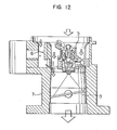
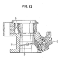
- Fig. 3 shows an example of the throttle actuator 4 including a dc motor in which the rotation of the dc motor 40 is transmitted at a reduced speed to a gear 42 through a gear 41 and an externally threaded rod 43 meshed with the internally threaded center hole of the gear 42 is moved in the directions of the arrows thus urging the lever 18 of the throttle valve 3 by a push rod 44 and thereby opening and closing the throttle valve 3.
- a dc motor in which the rotation of the dc motor 40 is transmitted at a reduced speed to a gear 42 through a gear 41 and an externally threaded rod 43 meshed with the internally threaded center hole of the gear 42 is moved in the directions of the arrows thus urging the lever 18 of the throttle valve 3 by a push rod 44 and thereby opening and closing the throttle valve 3.
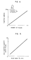
- the signal ⁇ TO is generated as a pulse signal as shown in Fig. 4 and the opening of the throttle valve 3 is controlled in accordance with the number of pulses in the signal.
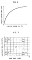
- the injector 5 is generally controlled by a pulse signal and Fig. 5 shows an example of the characteristic of the injector 5.
- the pulse width Tp represents the pulse width of the drive signal Ti or the duration of opening of the injector 5 and the fuel injection quantity represents the amount of fuel injected per pulse.
- Fig. 6 showing the relation between the throttle angle 8 TH and the actual opening area of the throttle valve 3, it will be seen that there is no linear relation between the throttle opening angle and the throttle valve opening area but the variation of the opening area increases in the small opening angle range and the variation of the opening area decreases with increase in the opening angle. Then, considering the resulting intake air flow to the engine, there results the nonlinear characteristic of Fig. 6 with the engine speed N as a parameter.
- the fuel quantity to be supplied is computed by detecting the throttle opening or the accelerator pedal position signal B AC , i.e., the driver's command signal
- a high degree of resolution is required for the throttle opening angle under such operating conditions where the amount of depression of the accelerator pedal is small and also the engine speed is low and it is necessary to ensure a high degree of resolution for the engine speed under such operating conditions where the engine speed is maintained low despite the increased amount of the accelerator depression.
- the present invention overcomes the foregoing deficiencies in the prior art and for this purpose a memory map as shown in Fig. 7 is used and the desired control is performed in accordance with the data preliminarily written in the memory map. This feature will now be described.
- the amount of fuel quantity to be injected per engine revolution (the consideration may be made in terms of the fuel quantity per cycle), it has a proportional relation to the amount of air flow Q'a per engine revolution.
- the engine speed N is determined, primarily the desired amount of air flow to the engine is determined by the accelerator pedal angle (position) 6 AC and consequently the desired fuel injection quantity can be obtained so far as the intake air flow Q'a is known.
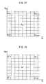
- the internal memory of the CPU is formed with m x n memory areas (or map areas) fox storing data Qa'mn as shown in Fig. 7 and these memory areas are arranged to correspond to m x n engine operating regions which are graphically represented with the ordinate representing the accelerator pedal angle ⁇ AC and the abscissa representing the engine speed N.
- a preset data Q'a corresponding to the values of 8 AC and N is preliminarily obtained by experiments or the like and stored for each of the operating regions.
- the map is searched in accordance with the then current accelerator pedal angle ⁇ AC and engine speed N so that the data Q'a is read from the corresponding memory area and used to calculate the desired opening duration Tp of the injector 5 from the following equation (1) and thereby control the fuel injection quantity.
- the corresponding signal data e TO for driving the throttle actuator 4 is calculated .
- the throttle actuator 4 is operated by the drive signal ⁇ TO thereby controlling the amount of intake air flow.
- the calculations of the data Tp and ⁇ TO are made according to the following simple expressions
- the control of the throttle valve can be effected by simply reading two data, i.e., the accelerator pedal angle ⁇ AC and the-engine speed N, obtaining the corresponding air flow Q'a by map searching and performing the simple calculation of obtaining the opening duration T as shown in Fig. 8. More specifically, at a step 81, the data ⁇ AC and N from the sensors 9 and 13 are read at intervals of 10 m sec, for example, in the execution of the flow-chart in Fig. 8. Then, the corresponding air flow Q'a is obtained by map searching from the map shown in Fig.
- the desired injector opening duration T p is calculated in accordance with the air flow Q'a and the engine speed N at a step 83.
- the desired drive signal data ⁇ TO is obtained from the map of Fig. 9 in accordance with the data Tp and the engine speed N.
- the data Q'a indicative of the amounts of intake air flow are written in the memory as will be seen from Fig. 7, the data Tp may be directly written in the memory in place of the data Q'a.
- This modification of the embodiment makes it possible to directly obtain the data T P by map searching with the result that the computing step of the data T in Fig. 8 is eliminated and the processing is made simpler and faster.
- the m x n different memory areas are arranged to correspond to the data Tp and N and the corresponding data ⁇ TO is written in each of the memory areas thereby obtaining the desired data ⁇ TO by searching the map as shown at the step 84.
- Fig. 10 shows another engine system which differs from the engine control system of Fig. 1 only in that a single fuel injection valve is used in place of a plurality of injection valves.
- Fig. 1 the same or equivalent components as used in Fig. 1 are designated by the same numerals as used in Fig. 10. These components are operated in the like manner as in Fig. 1 and will not be described.
- Fig. 11 corresponds to Fig. 2 and only a single injector 5 is included.
- the injector 5 used in the embodiment of Fig. 10 has a characteristic such that the fuel injection quantity per injection is increased substantially in proportion to the pulse width of the valve opening signal Tp as shown by the characteristic diagram of Fig. 5.
- the throttle actuator 4 has a characteristic such that the opening of the throttle valve 3 is increased substantially in proportion to the number of pulses of a pulse width t within a time interval T as shown by the characteristic diagram of Fig. 4. The use of the components of these characteristics has the advantage of making it possible to easily effect the control digitally.
- the air flow sensor 6 is of the type having the characteristic shown by the characteristic diagram of Fig. 15.
- Fig. 16 is a functional block diagram showing the contents of the control operation in the form of functional blocks, in which an accelerator position detection signal ⁇ AC and an engine speed detection signal N are applied to a first control unit 120 so that the optimum fuel injection quantity Q f to the operating conditions corresponding to the signals 8 AC and N is determined and the corresponding amount of intake air flow Q a to the fuel injection quantity Q f is determined so as to obtain the optimum air-fuel ratio. Then, the result is applied to a second control unit 121 so that the throttle valve opening ⁇ AC corresponding to the computed intake air flow Q a is determined and a drive signal ⁇ TO to be applied to the throttle actuator 4 is generated so as to attain the opening 8 AC .
- the actual amount of intake air flow Q is detected from the output signal of the air flow sensor 6 so that if there is any error between the desired value and the actual value, the pulse width of the drive signal ⁇ TO applied to the throttle actuator 4 is corrected so as to reduce the error to zero.
- the amount of intake air flow amount Q a follows up and corresponds to the fuel injection quantity Q f .
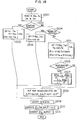
- Fig. 18 is a flow chart showing the control contents in greater detail and the operations corresponding to the flow chart are controlled by the CPU of the control circuit 10.
- the program shown by the flow chart is started each constant interval of time.
- the sensor output signals indicative of the throttle valve opening ⁇ AC , engine temperature T W , engine speed N, etc. are read in to detect the operating conditions of the engine (step 1200).
- the throttle valve opening is determined only in dependence on the engine temperature T W irrespective of the fuel injection quantity Q f .
- the fuel injection quantity Q f is determined in accordance with the engine temperature T W and the actual throttle valve opening 8 AC and the pulse width of the drive signal ⁇ TO to the throttle actuator 4 is set to a value proportional to the fuel injection quantity Q f (step 1205).
- the process is advanced to a step 1201 to calculate the supply amount of fuel Q f and the throttle valve opening ⁇ TO .
- a predetermined time delay value ⁇ is added to the differentiated value d ⁇ AC /dt (step 1207) and the drive signal ⁇ TO to the throttle actuator 4 which was previously determined at the step 1201 is delivered.
- control is effected such that if the value of f ( N , d ⁇ AC) is increased during the accelera- dt tion operation as shown by the following the time delay T is added and the time rate of change of the throttle valve 3 is decreased thereby enriching the A/F ratio during the initial period of the acceleration operation.
- the control is performed so that. even if the accelerator pedal is depressed rapidly, the rate of change of the drive signal ⁇ TO is reduced and the fuel is enriched.
- the execution number of the step 1207 is counted. Assuming that the counted value is NP, the modification of the value ⁇ TO is stopped until the value NP reaches to the value ⁇ operated in the step 1207. By this the control delay of the throttle valve 3 can be decided.
- NP ⁇ T the value ⁇ TO is modified each execution of the step 1207 by the value f(N , d ⁇ AC
- the execution of the step 1207 is effected at a constant interval of time. If the flow-chart of Fig. 18 is executed each 10 m second, for example, the execution of the step 1207 is also effected each 10 m sec. Therefore if the target value is modified by a single execution by the value of f(N, de ⁇ AC /dt), the throttle valve 3 is consequently changed by the value of d ⁇ TO /dt.
- the ⁇ TO is changed after the lapse of time corresponding to the value T , however alternatively it may be possible to gradually increase the changing value of the ⁇ TO together with the count value NP, thereby to.change it by the value of f(N, d ⁇ AC /dt) each one execution after the lapse of time corresponding to the value T .
- the ideal A/F is read from aumap of the actual amounts of intake air flow Q and the engine speeds N as shown in Fig. 19 and it ie compared with the A/F due to the amount of intake air flow that would be supplied by the pulse width of the drive signal ⁇ TQ previously obtained from the map at the step 1201 to compute any difference between the two. If there is the difference, the pulse width of the drive signal ⁇ TO is corrected so as to reduce the difference to zero (steps 1208 and 1210).
- the thus computed fuel injection quantity Q f is then delivered as a valve opening signal Tp to be applied to the injector 5. Then, the drive signal ⁇ TO is also applied to the throttle actuator 4.
- the fuel injection quantity and the throttle valve opening are optimized to suit the engine operating conditions. Since this control is performed by the preferential fuel control method, there is the effect of considerably improving the drivability during the transitional period of the engine operating conditions such as the acceleration operation.
- the engine control is performed in such a manner that a satisfactory control response characteristic is ensured, that the high-accuracy A/F control is always effected under various engine operating conditions including the transitional conditions, that the deterioration of exhaust gas emission is reduced and that the driving characteristic is improved.
Landscapes
- Engineering & Computer Science (AREA)
- Chemical & Material Sciences (AREA)
- Combustion & Propulsion (AREA)
- Mechanical Engineering (AREA)
- General Engineering & Computer Science (AREA)
- Electrical Control Of Air Or Fuel Supplied To Internal-Combustion Engine (AREA)
Applications Claiming Priority (4)
| Application Number | Priority Date | Filing Date | Title |
|---|---|---|---|
| JP21916983A JPS60111046A (ja) | 1983-11-21 | 1983-11-21 | エンジン制御装置 |
| JP219169/83 | 1983-11-21 | ||
| JP22224583A JPS60116835A (ja) | 1983-11-28 | 1983-11-28 | エンジン制御装置 |
| JP222245/83 | 1983-11-28 |
Publications (2)
| Publication Number | Publication Date |
|---|---|
| EP0142856A2 true EP0142856A2 (de) | 1985-05-29 |
| EP0142856A3 EP0142856A3 (de) | 1987-02-04 |
Family
ID=26522959
Family Applications (1)
| Application Number | Title | Priority Date | Filing Date |
|---|---|---|---|
| EP84114026A Withdrawn EP0142856A3 (de) | 1983-11-21 | 1984-11-20 | Steuereinrichtung des Luft-Kraftstoffverhältnisses in einer Brennkraftmaschine |
Country Status (3)
| Country | Link |
|---|---|
| US (1) | US4590912A (de) |
| EP (1) | EP0142856A3 (de) |
| KR (1) | KR890000500B1 (de) |
Cited By (11)
| Publication number | Priority date | Publication date | Assignee | Title |
|---|---|---|---|---|
| DE3721910A1 (de) * | 1986-07-02 | 1988-01-07 | Nissan Motor | Verfahren und einrichtung zur erfassung des ansaugvolumens fuer eine brennkraftmaschine oder dergleichen |
| EP0239095A3 (en) * | 1986-03-26 | 1988-02-24 | Hitachi, Ltd. | A control system and method for internal combustion engines |
| EP0196657A3 (en) * | 1985-04-02 | 1988-03-02 | Hitachi, Ltd. | Electronic fuel injection method and apparatus for interelectronic fuel injection method and apparatus for internal combustion engine nal combustion engine |
| WO1988006235A1 (en) * | 1987-02-12 | 1988-08-25 | Mitsubishi Denki Kabushiki Kaisha | Method and device for controlling the operation of an engine for a vehicle |
| WO1988006234A1 (en) * | 1987-02-12 | 1988-08-25 | Mitsubishi Denki Kabushiki Kaisha | Method and device for controlling the operation of an engine for a vehicle |
| EP0281152A3 (en) * | 1987-03-06 | 1988-12-14 | Hitachi, Ltd. | A fuel supply control method and apparatus for internal combustion engines |
| EP0251708A3 (en) * | 1986-06-27 | 1989-03-22 | Engelhard Corporation | Improved catalyst compositions and methods of making same |
| US4873641A (en) * | 1986-07-03 | 1989-10-10 | Nissan Motor Company, Limited | Induction volume sensing arrangement for an internal combustion engine or the like |
| WO1991004401A1 (de) * | 1989-09-12 | 1991-04-04 | Robert Bosch Gmbh | Verfahren zum einstellen von luft- und kraftstoffmengen für eine mehrzylindrige brennkraftmaschine |
| EP0413432A3 (en) * | 1989-08-14 | 1991-05-02 | General Motors Corporation | Emission control system for a crankcase-scavenged two-stroke engine operating near idle |
| EP0687809A3 (de) * | 1994-06-17 | 1997-10-22 | Hitachi Ltd | Ausgangsdrehmoment-Steuerungsvorrichtung und Verfahren für eine Brennkraftmaschine |
Families Citing this family (12)
| Publication number | Priority date | Publication date | Assignee | Title |
|---|---|---|---|---|
| JPS61223247A (ja) * | 1985-03-27 | 1986-10-03 | Honda Motor Co Ltd | 内燃エンジンの加速時の燃料供給制御方法 |
| US4700681A (en) * | 1985-04-08 | 1987-10-20 | Toyota Jidosha Kabushiki Kaisha | Fuel injection system for an internal combustion engine |
| US4723524A (en) * | 1985-06-05 | 1988-02-09 | Hitachi, Ltd. | Fuel injection controlling method for an internal combustion engine |
| JP2517909B2 (ja) * | 1986-05-29 | 1996-07-24 | 株式会社日立製作所 | 内燃機関制御システムおよびその制御方法 |
| JPS6361739A (ja) * | 1986-09-01 | 1988-03-17 | Hitachi Ltd | 燃料制御装置 |
| JP2734060B2 (ja) * | 1989-02-28 | 1998-03-30 | 三菱自動車工業株式会社 | 内燃機関の吸入空気量制御方法 |
| US5408973A (en) * | 1993-11-26 | 1995-04-25 | Spangjer; Keith G. | Internal combustion engine fuel supply system and method |
| JPH0835438A (ja) | 1994-07-25 | 1996-02-06 | Hitachi Ltd | エンジンパワートレインの制御方法 |
| JP2000097086A (ja) | 1998-09-18 | 2000-04-04 | Hitachi Ltd | エンジンの吸入空気流量制御方法、制御装置および出力制御方法 |
| US6032640A (en) * | 1998-10-02 | 2000-03-07 | The University Of British Columbia | Control method for spark-ignition engines |
| FR2804179B1 (fr) * | 2000-01-20 | 2002-12-06 | Peugeot Citroen Automobiles Sa | Procede et dispositif de regulation de la richesse du melange d'un moteur a combustion interne |
| CN113728157B (zh) * | 2019-05-03 | 2025-04-01 | 沃尔布罗有限责任公司 | 用于燃烧发动机的低压燃料喷射系统 |
Family Cites Families (12)
| Publication number | Priority date | Publication date | Assignee | Title |
|---|---|---|---|---|
| CH514780A (de) * | 1970-03-26 | 1971-10-31 | Bosch Gmbh Robert | Anordnung zur elektronischen Gemischdosierung bei Ottomotoren |
| US4138979A (en) * | 1977-09-29 | 1979-02-13 | The Bendix Corporation | Fuel demand engine control system |
| DE2837820A1 (de) * | 1978-08-30 | 1980-03-13 | Bosch Gmbh Robert | Einrichtung zum bestimmen der einer brennkraftmaschine zuzufuehrenden kraftstoffmenge |
| DE2847021A1 (de) * | 1978-10-28 | 1980-05-14 | Bosch Gmbh Robert | Vorrichtung zur regelung von betriebskenngroessen einer brennkraftmaschine auf optimale werte |
| DE2918135C3 (de) * | 1979-05-05 | 1981-08-06 | Volkswagenwerk Ag, 3180 Wolfsburg | Verfahren zum Betrieb einer fremdgezündeten Brennkraftmaschine und Anordnung zur Durchführung des Verfahrens |
| US4335695A (en) * | 1979-10-01 | 1982-06-22 | The Bendix Corporation | Control method for internal combustion engines |
| JPS56107925A (en) * | 1980-01-31 | 1981-08-27 | Mikuni Kogyo Co Ltd | Electronically controlled fuel injector for ignited internal combustion engine |
| JPS5791343A (en) * | 1980-11-28 | 1982-06-07 | Mikuni Kogyo Co Ltd | Electronically controlled fuel injector for ignition internal combustion engine |
| US4398515A (en) * | 1981-06-18 | 1983-08-16 | Texaco Inc. | Internal combustion engine fuel control system |
| EP0095190B1 (de) * | 1982-05-26 | 1989-03-15 | Hitachi, Ltd. | Elektronisch gesteuertes Einspritzsystem für Brennkraftmaschinen |
| US4470396A (en) * | 1982-12-02 | 1984-09-11 | Mikuni Kogyo Kabushiki Kaisha | Internal combustion engine control system with means for reshaping of command from driver's foot pedal |
| JPH0733781B2 (ja) * | 1983-08-26 | 1995-04-12 | 株式会社日立製作所 | エンジン制御装置 |
-
1984
- 1984-11-15 KR KR1019840007164A patent/KR890000500B1/ko not_active Expired
- 1984-11-16 US US06/672,367 patent/US4590912A/en not_active Expired - Fee Related
- 1984-11-20 EP EP84114026A patent/EP0142856A3/de not_active Withdrawn
Cited By (17)
| Publication number | Priority date | Publication date | Assignee | Title |
|---|---|---|---|---|
| EP0196657A3 (en) * | 1985-04-02 | 1988-03-02 | Hitachi, Ltd. | Electronic fuel injection method and apparatus for interelectronic fuel injection method and apparatus for internal combustion engine nal combustion engine |
| EP0239095A3 (en) * | 1986-03-26 | 1988-02-24 | Hitachi, Ltd. | A control system and method for internal combustion engines |
| EP0251708A3 (en) * | 1986-06-27 | 1989-03-22 | Engelhard Corporation | Improved catalyst compositions and methods of making same |
| DE3721910C2 (de) * | 1986-07-02 | 1998-04-23 | Nissan Motor | Verfahren zum indirekten Abschätzen der in eine Brennkraftmaschine eingeführten Luftmenge |
| DE3721910A1 (de) * | 1986-07-02 | 1988-01-07 | Nissan Motor | Verfahren und einrichtung zur erfassung des ansaugvolumens fuer eine brennkraftmaschine oder dergleichen |
| US4951209A (en) * | 1986-07-02 | 1990-08-21 | Nissan Motor Co., Ltd. | Induction volume sensing arrangement for internal combustion engine or the like |
| US4873641A (en) * | 1986-07-03 | 1989-10-10 | Nissan Motor Company, Limited | Induction volume sensing arrangement for an internal combustion engine or the like |
| WO1988006234A1 (en) * | 1987-02-12 | 1988-08-25 | Mitsubishi Denki Kabushiki Kaisha | Method and device for controlling the operation of an engine for a vehicle |
| US5025380A (en) * | 1987-02-12 | 1991-06-18 | Mitsubishi Denki Kabushiki Kaisha | Method and device for controlling the operation of an engine for a vehicle |
| DE3890114C2 (de) * | 1987-02-12 | 1995-04-27 | Mitsubishi Electric Corp | Verfahren und Vorrichtung zum Regeln eines Kraftfahrzeugmotors |
| WO1988006235A1 (en) * | 1987-02-12 | 1988-08-25 | Mitsubishi Denki Kabushiki Kaisha | Method and device for controlling the operation of an engine for a vehicle |
| EP0281152A3 (en) * | 1987-03-06 | 1988-12-14 | Hitachi, Ltd. | A fuel supply control method and apparatus for internal combustion engines |
| EP0413432A3 (en) * | 1989-08-14 | 1991-05-02 | General Motors Corporation | Emission control system for a crankcase-scavenged two-stroke engine operating near idle |
| WO1991004401A1 (de) * | 1989-09-12 | 1991-04-04 | Robert Bosch Gmbh | Verfahren zum einstellen von luft- und kraftstoffmengen für eine mehrzylindrige brennkraftmaschine |
| US5095874A (en) * | 1989-09-12 | 1992-03-17 | Robert Bosch Gmbh | Method for adjusted air and fuel quantities for a multi-cylinder internal combustion engine |
| AU630994B2 (en) * | 1989-09-12 | 1992-11-12 | Robert Bosch Gmbh | Process for adjusting quantities of air and fuel in a multi-cylinder internal combustion engine |
| EP0687809A3 (de) * | 1994-06-17 | 1997-10-22 | Hitachi Ltd | Ausgangsdrehmoment-Steuerungsvorrichtung und Verfahren für eine Brennkraftmaschine |
Also Published As
| Publication number | Publication date |
|---|---|
| KR850003925A (ko) | 1985-06-29 |
| EP0142856A3 (de) | 1987-02-04 |
| US4590912A (en) | 1986-05-27 |
| KR890000500B1 (ko) | 1989-03-20 |
Similar Documents
| Publication | Publication Date | Title |
|---|---|---|
| US4590912A (en) | Air-fuel ratio control apparatus for internal combustion engines | |
| EP0239095B1 (de) | Methode und System zur Steuerung von Innen-Verbrennungsmaschinen | |
| US4403584A (en) | Method and apparatus for optimum control for internal combustion engines | |
| US4905653A (en) | Air-fuel ratio adaptive controlling apparatus for use in an internal combustion engine | |
| US4552116A (en) | Engine control apparatus | |
| US4548181A (en) | Method of controlling the fuel supply to an internal combustion engine at acceleration | |
| US4789939A (en) | Adaptive air fuel control using hydrocarbon variability feedback | |
| US4462378A (en) | Control apparatus for an internal combustion engine having a carburetor | |
| US4389996A (en) | Method and apparatus for electronically controlling fuel injection | |
| EP0924420B1 (de) | Drehmomentregler für eine Brennkraftmaschine | |
| US5058550A (en) | Method for determining the control values of a multicylinder internal combustion engine and apparatus therefor | |
| US5058556A (en) | Device for determining activated condition of an oxygen sensor | |
| US4667631A (en) | Method and apparatus for controlling air-fuel ratio in internal combustion engine | |
| US4995366A (en) | Method for controlling air-fuel ratio for use in internal combustion engine and apparatus for controlling the same | |
| US5495841A (en) | Device and method of correcting the fuel amount supplied to Otto engines | |
| US4739739A (en) | Fuel-injection control system for an internal combustion engine | |
| EP0167839B1 (de) | Kraftstoffeinspritzungssteuergerät für eine Innenbrennkraftmaschine | |
| US4455981A (en) | Method and system for control of air-fuel ratio | |
| US5775295A (en) | Process for controlling a direct-injection internal combustion engine | |
| JP2712153B2 (ja) | 内燃機関の負荷検出装置 | |
| JP7737345B2 (ja) | 内燃機関の燃料噴射制御装置 | |
| JPH0325622B2 (de) | ||
| JP2590823B2 (ja) | 内燃機関の空燃比制御装置 | |
| JP2561248B2 (ja) | 内燃機関の燃料カツト制御装置 | |
| JP3453830B2 (ja) | エンジンの空燃比制御装置 |
Legal Events
| Date | Code | Title | Description |
|---|---|---|---|
| PUAI | Public reference made under article 153(3) epc to a published international application that has entered the european phase |
Free format text: ORIGINAL CODE: 0009012 |
|
| AK | Designated contracting states |
Designated state(s): CH DE FR GB IT LI NL SE |
|
| PUAL | Search report despatched |
Free format text: ORIGINAL CODE: 0009013 |
|
| AK | Designated contracting states |
Kind code of ref document: A3 Designated state(s): CH DE FR GB IT LI NL SE |
|
| 17P | Request for examination filed |
Effective date: 19870206 |
|
| 17Q | First examination report despatched |
Effective date: 19870626 |
|
| STAA | Information on the status of an ep patent application or granted ep patent |
Free format text: STATUS: THE APPLICATION HAS BEEN WITHDRAWN |
|
| 18W | Application withdrawn |
Withdrawal date: 19871026 |
|
| RIN1 | Information on inventor provided before grant (corrected) |
Inventor name: ATAGO, TAKESHI |