EP0142964A2 - Dispositif et méthode d'impression thermique par transfert d'encre - Google Patents
Dispositif et méthode d'impression thermique par transfert d'encre Download PDFInfo
- Publication number
- EP0142964A2 EP0142964A2 EP84307737A EP84307737A EP0142964A2 EP 0142964 A2 EP0142964 A2 EP 0142964A2 EP 84307737 A EP84307737 A EP 84307737A EP 84307737 A EP84307737 A EP 84307737A EP 0142964 A2 EP0142964 A2 EP 0142964A2
- Authority
- EP
- European Patent Office
- Prior art keywords
- heat generating
- generating resistor
- energizing
- duration
- desired density
- Prior art date
- Legal status (The legal status is an assumption and is not a legal conclusion. Google has not performed a legal analysis and makes no representation as to the accuracy of the status listed.)
- Granted
Links
Images


Classifications
-
- H—ELECTRICITY
- H04—ELECTRIC COMMUNICATION TECHNIQUE
- H04N—PICTORIAL COMMUNICATION, e.g. TELEVISION
- H04N1/00—Scanning, transmission or reproduction of documents or the like, e.g. facsimile transmission; Details thereof
- H04N1/40—Picture signal circuits
- H04N1/40025—Circuits exciting or modulating particular heads for reproducing continuous tone value scales
- H04N1/40031—Circuits exciting or modulating particular heads for reproducing continuous tone value scales for a plurality of reproducing elements simultaneously
-
- B—PERFORMING OPERATIONS; TRANSPORTING
- B41—PRINTING; LINING MACHINES; TYPEWRITERS; STAMPS
- B41J—TYPEWRITERS; SELECTIVE PRINTING MECHANISMS, i.e. MECHANISMS PRINTING OTHERWISE THAN FROM A FORME; CORRECTION OF TYPOGRAPHICAL ERRORS
- B41J2/00—Typewriters or selective printing mechanisms characterised by the printing or marking process for which they are designed
- B41J2/315—Typewriters or selective printing mechanisms characterised by the printing or marking process for which they are designed characterised by selective application of heat to a heat sensitive printing or impression-transfer material
- B41J2/32—Typewriters or selective printing mechanisms characterised by the printing or marking process for which they are designed characterised by selective application of heat to a heat sensitive printing or impression-transfer material using thermal heads
- B41J2/35—Typewriters or selective printing mechanisms characterised by the printing or marking process for which they are designed characterised by selective application of heat to a heat sensitive printing or impression-transfer material using thermal heads providing current or voltage to the thermal head
- B41J2/355—Control circuits for heating-element selection
Definitions
- This invention relates generally to thermal ink transfer printing apparatus, and particularly to such apparatus which is capable of selecting a desired tone value for each picture element.
- Thermal ink transfer printing whose principle is shown in Fig. 1, is arranged such that a print sheet 1 and an ink transfer sheet contacting each other are sent to a portion between a platen roller 3 and a thermal head 4, and when the ink transfer sheet 2 is heated with respective heat generating resistors of the thermal head 4 being operated to generate heat by applying currents to the respective heat generating resistors, thermally fusable ink 2' painted on the ink transfer sheet 2 at a constant thickness is molten to be transferred to the print sheet 1, and then the print sheet to which ink transfer printing has been effected is cut to have a suitable shape so as to be a printed matter, while the ink transfer sheet which has become unnecessary is taken up by a take up roller via a guide roller so as to be disposed.
- tone value printing in such thermal ink transfer printing is effected such that a given area of ink on the ink transfer sheet is molten by way of a heat generating resistor so as to obtain a given density, namely, area control is effected such that when density is low, the area to be molten is small and when density is high, the area to be molten is large.
- each heat generating resistor is made small so as to obtain a fine printing result, since maximum area cannot be made large on tone value printing, accurate density indication cannot be performed because white-omission occurs when it is required to perform uniform-density printing over a relatively large area.
- power is made large so as to obtain a density or tone value similar to uniform-density printing, then there is a drawback that the heat generating resistor burns out.
- linear printing cannot be performed since the input signal and temperature rise are not in linear relationship.
- the present invention has been developed in order to remove the above-described drawbacks inherent to the conventional thermal ink transfer printing apparatus.
- At least two consecutive heat generating resistors in an array of the same are used such that one or both of the two heat generating resistors are/is energized depending on a desired density of a pixel of an image to be printed by a thermal ink transfer printing apparatus where the end timing of energizing duration of the two heat generating resistors is made equal to each other.
- an apparatus for thermal ink transfer printing comprising: a thermal head having a plurality of heat generating resistors arranged in line for melting thermally fusable ink attached to an ink sheet, first and second groups of heat generating resistors respectively corresponding to two alternate arrangements of the heat generating resistors being arranged so that each of the second group is positioned within a pre-heating region of the first group; a head driving circuit responsive to an input signal for energizing the heat generating resistors such that each datum representing a desired density of a pixel is used to energize first and/or second heat generating resistors positioned close to each other, the first heat generating resistor being of the first group and the second heat generating resistor being of the second group, the head driving circuit having; first means responsive to the input signal for detecting the desired density; second means for energizing only the first heat generating resistor when the desired density is samller than a predetermined value, the second means en
- the third means for energizing both the first and second heat generating resistors when the desired density is equal to or greater than the predetermined value, the third means energizing the first heat generating resistor for a predetermined maxium duration and the second heat generating resistor, for a duration determined by the desired density, in such a manner that an end of the energizing duration of the second heat generating resistor corresponds to an end of the energizing duration of the first heat generating resistor.
- a method of thermal ink transfer printing using a thermal head having a plurality of heat generating resistors arranged in line for melting thermally fusable ink attached to an ink sheet comprising the steps of: decoding an input signal for detecting a desired density of each pixel which is formed by first and second heat generating resistors arranged close to each other; energizing only the first heat generating resistor when the desired density is samller than a predetermined value, for a duration determined by the desired density; and energizing both the first and second heat generating resistors when the desired density is equal to or greater than the predetermined value, the first heat generating resistor being energized for a predetermined maxium- duration and the second heat generating resistor being energized for a duration determined by the desired density in such a manner that an end of the energizing duration of the second heat generating resistor corresponds to an end of the energizing duration of the first heat generating
- a thermal head used for thermal ink transfer printing apparatus comprises a plurality of heat generating resistors arranged in line or matrix.
- each heat generating resistor is used for each pixel (picture element) signal in conventional apparatus, two or more heat generating resistors are used for a single pixel signal in the present invention.
- each pixel signal is used to drive one or both of the two heat generating resistors in the case two heat generating resistors are provided for each pixel.
- a plurality of heat generating resistors arranged in line in a thermal head are divided into two sets or groups each including alternate heat generating resistors. These sets are referred to as first and second sets, and heat generating resistors belonging to the first or second set are referred to as first or second heat generating resistors.
- the thermally fusable ink painted on the ink transfer sheet at a given thickness is molten for a given area so as to obtain a given density of a pixel signal by way of two heat generating resistors which are adjacent to each other thereby performing thermal ink transfer printing.
- the energizing duration of one heat generating resistor is set to a constant maximum value, while the energizing duration of the remaining heat generating resistor is controlled in accordance with the density.
- This energizing duration is set to be within the above-mentioned constant maximum energizing duration, and the ending time of energization of the two heat generating resisors for instance is made equal to each other.
- Fig. 2 is an explanatory diagram of heat generating resistors corresponding to two pixels, which are built in a thermal head of a tone value thermal ink transfer printing apparatus shown in Fig. 1.
- the thermal head 4 comprises a plurality of heat generating resistors lla, llb, arranged line and only four of them are shown in Fig. 2 for simplicity.
- the direction of the allignment of the heat generating resistors lla, llb is substantially normal to a direction of the relative movement between the thermal head 4 and the print sheet 1.
- the relative motion of the print sheet 1 is shown by an arrow X in Fig. 2.
- Fig. 3 is an explanatory diagram showing the relationship between energizing durations of the two heat generating resistors shown in Fig. 2, and the result of printing.
- the references al to a4 and bl to b4 show heating durations and the references cl to c4 show ink-melting areas on the ink transfer sheet 13 caused by the heat.
- the references dl to d4 show cross-sectional views showing the state of fused ink attached to the print sheet 12.
- heat generating resistors indicated at the reference lla are of the first set, while other heat generating resistors indicated at the reference llb are of the second set.
- the first set and second set heat generating resistors lla and llb are respcectively arranged alternately.
- One of the two heat generating resistors lla of the first set, which is show at the left, is referred to as a first heat generating resistor
- the heat generating resistor llb positioned at the right of the first heat generatign resitor lla is referred to as a second heat generating resistor for simplicity.
- first and second heat generating resistors lla and llb are used to form a combination so that density data or signal corresponding to a single pixel is used for this combination of the two heat generating resistors lla and llb.
- a tone value of a single pixel is determined by one or both of the first and second heat generating resistors lla and llb as will be described in detail hereinafter.
- a desired tone value or density of the corresponding pixel is below half the maximum density thereof, then only the heat generating resistor lla is energized such that its energizing duration is controlled so that the density linearly changes.
- both the first and second heat generating resistors lla and llb are energized.
- the first and second heat generating resistors lla and llb are arranged such that the interval or pitch therebetween is made one half the interval between pixels.
- the second heat generating resistor llb is located so that it resides in a pre-heating region P of the heat generating resistors lla of the first set.
- the pre-heating region P is a place where the heat generated by the heat generating resistors lla is transmitted to ink of the ink transfer sheet so that the ink will readily melt when the termperature is further raised.
- the ink corresponding to the pre-heating region P is not molten by only the heat from the first heat generating resistor lla.
- a region Tl enclosed by a solid line which is outside the heat generating resistor lla indicates a melting region of the thermally fusable ink on energization of the first heat generating resistor lla for a maxium energizing duration T 1
- regions ⁇ T 2 , ⁇ T 3 , AT 4 enclosed by one-dot-dash line to three-dot-dash line at the heating resistor llb indicate melting regions of the thermally fusable ink on energization of the heat generating resistor llb for durations ⁇ T 2 , ⁇ T 3 , ⁇ T 4 .
- the first heat generating resistor lla is energized for a period (maximum period) T corresponding to half the maximum density, while the second heat generating resistor llb is also energized for a period corresponding to the density of the pixel, namely for ⁇ T 2 , ⁇ T 3 , or ⁇ T 4 .
- This duration for which the second heat generating resistor llb is energized is be within Tl for which the first heat generating resistor lla is energized, and the end timing of energization of the heat generating resistors lla and llb are the same as shown in the waveforms a2, b2, a3, b3 and a4, b4 of Fig. 3.
- the thermally fusable ink on the ink transfer sheet which is to be molten by the second heat generating resistor llb is ready to be molten at the time of energization of the second heat generating resistor llb. Therefore, the ink at this portion redily melts when the second heat generating resistor llb is energized.
- the energizing duration of the second heat generating resistor 11 for obtaining a desired density can be readily calculated in advance since pre-heating time; i.e. Tl-AT2, Tl-A3 or Tl-AT4, is known and melting characteristic of the ink is also known.
- the end timing of energizing durations of the first and second heat generating resistors lla and llb are made equal to each other as shown in the waveforms a2, b2, a3, b3, a4, b4 of Fig. 3, the energizing duration AT2, ⁇ T3 and ⁇ T4 can be accurately determined in advance considering the pre-heating time so that accurate tone value control is achieved. More specifically, tone value or density of each pixel exhibited on a print sheet is substantially proportional to the tone value or density represented by the input signal or data as seen in Fig. 4. In other words, superior linearlity is ensured.
- the number of heat generating resistors may be increased as 3, 4 ... for a single pixel signal.
- the number of heat generating resistors may be increased as 3, 4 ... for a single pixel signal.
- only one of the three heat generating resistors may be energized when a desired density is below 1/3 the maximum density, and remainging one or.two heat generating resistors may be enerigzed as the density increaes.
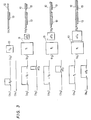
- the present invention will be further described with reference to Fig. 5 showing a thermal head driving circuit used for the thermal ink transfer printer according to the present invention.
- the head drive circuit comprises nine integral circuits IC1 to IC9, and data input terminals DO to D4. In addition some other input terminals CLOCK, LOAD and STROBE are provided for receiving such labeled signals.
- the input data fed to the data input terminals DO to D4 is a digital signal indicative of a desired tone value of each pixel.
- the integrated circuits IC1, IC5 and IC9 are selectors which select one of two input data fed to first and second sets of input terminals A and B respectively in accordance with a signal fed to its SELECT terminal.
- IC4 is a frequency divider for dividing the frequency of clock pulses.
- IC2 is an inverter.
- IC3 and IC6 form a substractor.
- IC 7 is a digital comparator, and IC8 is a counter for counting the number of LOAD pulses. Preferable types of these ICs are labelled in Fig. 5.
- An output signal from the IC7 is fed to a shift register of the thermal head having a latch circuit and a gate circuit as well as an array of heat generating resistors Rl, R2 ... Rn and associated switching transistors.
- the latch circuit is controlled by the LOAD signal, while the gate circuit is controlled by the STROBE signal. Shifting in the shift register is effected in response to clock pulses.
- Tone value data fed to input terminals DO to D4 is fed such that lower four bits fed to terminals DO to D3 are fed to a first set of input terminals A of the IC1 whose other or second set of input terminals B receive high level signals expressed in terms of H.
- the MSB fed to the terminal D4 is fed to the SELECT terminal of the ICl so that high level signals H are outputted when MSB is of high level, and tone value data fed to DO to Dl is outputted when the MSB is of low level.
- references H and L are used to indicate high and low levels respectively, and the reference DO to D4 representing the input terminals are also used to designate the signals or data fed to these terminals.
- the output data from the IC1 is fed to a first set of input terminals A of the IC5.
- the tone value data DO to D3 is fed to the IC2 to be inverted therein so that inverted tone value data DO to D3 is fed to a first set of input terminals A of the IC3 whose second set of input terminals B receive H signals.
- input data fed to the first set of input terminals A is added- to the high level data fed to the second set of input terminals B to produce output data indicative of the sum obtained as the result of addition.
- the sum data is fed from the output of the IC3 to a first set of input terminals A of the IC6 whose second set of input terminals B receive an H signal at only LSB terminal, remaining terminals of the second set B being grounded.
- the data fed to the first set of input terminals A is added to the data fed to second set of input terminals B so that a difference between a maximum four bit value and the data represented by DO to D3 is produced and fed from the IC6 to a set of input terminals B of the IC9.
- the IC9 is responsive to MSB (D4) for selecting the data fed to terminals B or the other data fed to the other set of terminals A all grounded to receive L signals.
- D4 is L
- L signls are outputted from the IC9.
- D4 is H
- the difference data from the IC6 is outputted.
- the IC4 responsive to a clock train divides the frequency of the clock pulses by two, and a frequency-divided clock pulses are fed to SELECT terminal of the IC5.
- the first set of input terminals A of the IC5 receives the output data from the IC1, i.e. DO to D3 when D4 is L, and H signals when D4 is H, while the second set of input terminals B receive L signals when D4 is L, and the difference data when D4 is H.
- These two data respectively fed to first and second sets of input terminals A and B are alternately fed to the IC7 in response to the pulses fed to SELECT terminal of the IC5.
- the data fed to a first set of input terminals A of the IC7 is compared with data at the second set of input temrinals B, and output data from the IC7 is fed to the shift register so as to drive the thermal head.
- the IC8 is responsive to the LOAD pulses so as to count up the number of the same in sequence till one half the maximum tone value, and the count is fed to the second set of input terminals B of the IC7.
- the LOAD pulse which is used by the latch of the thermal head, appears each time the number of clock pulses reaches the total number of heat generating resistors Rl, R2 ... Rn.
Landscapes
- Engineering & Computer Science (AREA)
- Multimedia (AREA)
- Signal Processing (AREA)
- Electronic Switches (AREA)
Applications Claiming Priority (2)
| Application Number | Priority Date | Filing Date | Title |
|---|---|---|---|
| JP58211716A JPS60104351A (ja) | 1983-11-12 | 1983-11-12 | 感熱転写記録方法 |
| JP211716/83 | 1983-11-12 |
Publications (3)
| Publication Number | Publication Date |
|---|---|
| EP0142964A2 true EP0142964A2 (fr) | 1985-05-29 |
| EP0142964A3 EP0142964A3 (en) | 1986-06-18 |
| EP0142964B1 EP0142964B1 (fr) | 1989-07-26 |
Family
ID=16610412
Family Applications (1)
| Application Number | Title | Priority Date | Filing Date |
|---|---|---|---|
| EP84307737A Expired EP0142964B1 (fr) | 1983-11-12 | 1984-11-09 | Dispositif et méthode d'impression thermique par transfert d'encre |
Country Status (4)
| Country | Link |
|---|---|
| US (1) | US4555714A (fr) |
| EP (1) | EP0142964B1 (fr) |
| JP (1) | JPS60104351A (fr) |
| DE (1) | DE3479109D1 (fr) |
Cited By (3)
| Publication number | Priority date | Publication date | Assignee | Title |
|---|---|---|---|---|
| DE3534144A1 (de) * | 1984-09-27 | 1986-04-03 | Kabushiki Kaisha Toshiba, Kawasaki, Kanagawa | Verfahren und vorrichtung zum drucken eines bildes |
| EP0329369A3 (en) * | 1988-02-15 | 1989-11-29 | Shinko Denki Kabushiki Kaisha | Method and apparatus for energizing thermal head of a thermal printer |
| EP0423797A3 (en) * | 1989-10-19 | 1991-11-06 | Canon Kabushiki Kaisha | Driving device for recording head and recording apparatus having said device |
Families Citing this family (10)
| Publication number | Priority date | Publication date | Assignee | Title |
|---|---|---|---|---|
| JPS61192569A (ja) * | 1985-02-21 | 1986-08-27 | Tokyo Electric Co Ltd | 計量印字装置 |
| JPS61193871A (ja) * | 1985-02-22 | 1986-08-28 | Tokyo Electric Co Ltd | 計量印字装置 |
| JPS61195863A (ja) * | 1985-02-25 | 1986-08-30 | Tokyo Electric Co Ltd | 計量印字装置 |
| US4703511A (en) * | 1986-10-09 | 1987-10-27 | Paul Conoval | Writing input and dynamics regeneration device |
| JP2830934B2 (ja) * | 1987-09-29 | 1998-12-02 | 日本電気ホームエレクトロニクス株式会社 | 濃度階調制御型サーマルプリンタ |
| US5546114A (en) * | 1991-09-18 | 1996-08-13 | Tektronix, Inc. | Systems and methods for making printed products |
| US5512930A (en) * | 1991-09-18 | 1996-04-30 | Tektronix, Inc. | Systems and methods of printing by applying an image enhancing precoat |
| US5434596A (en) * | 1992-10-02 | 1995-07-18 | Eastman Kodak Company | Quarter-tone thermal backprinting |
| JPH0890820A (ja) * | 1994-09-26 | 1996-04-09 | Nec Corp | サーマルヘッド駆動方法および装置 |
| DE19521455A1 (de) * | 1995-06-13 | 1996-12-19 | Esselte Meto Int Gmbh | Steuerschaltung für einen Thermodrucker |
Family Cites Families (6)
| Publication number | Priority date | Publication date | Assignee | Title |
|---|---|---|---|---|
| US4084259A (en) * | 1973-11-30 | 1978-04-11 | The Mead Corporation | Apparatus for dot matrix recording |
| US3953708A (en) * | 1975-04-25 | 1976-04-27 | Xerox Corporation | Thermal printer using amorphous semiconductor devices |
| CA1073960A (fr) * | 1977-07-14 | 1980-03-18 | David R. Baraff | Barre d'impression thermique |
| FR2485796A1 (fr) * | 1980-06-24 | 1981-12-31 | Thomson Csf | Resistance electrique chauffante et tete d'imprimante thermique comportant de telles resistances chauffantes |
| JPS5779763A (en) * | 1980-11-06 | 1982-05-19 | Sony Corp | Drive method of thermo-sensing picture display device |
| JPS58212970A (ja) * | 1982-06-07 | 1983-12-10 | Fuji Xerox Co Ltd | 感熱記録装置 |
-
1983
- 1983-11-12 JP JP58211716A patent/JPS60104351A/ja active Granted
-
1984
- 1984-11-09 EP EP84307737A patent/EP0142964B1/fr not_active Expired
- 1984-11-09 DE DE8484307737T patent/DE3479109D1/de not_active Expired
- 1984-11-09 US US06/669,783 patent/US4555714A/en not_active Expired - Lifetime
Cited By (5)
| Publication number | Priority date | Publication date | Assignee | Title |
|---|---|---|---|---|
| DE3534144A1 (de) * | 1984-09-27 | 1986-04-03 | Kabushiki Kaisha Toshiba, Kawasaki, Kanagawa | Verfahren und vorrichtung zum drucken eines bildes |
| DE3534144C2 (fr) * | 1984-09-27 | 1990-11-15 | Kabushiki Kaisha Toshiba, Kawasaki, Kanagawa, Jp | |
| EP0329369A3 (en) * | 1988-02-15 | 1989-11-29 | Shinko Denki Kabushiki Kaisha | Method and apparatus for energizing thermal head of a thermal printer |
| EP0423797A3 (en) * | 1989-10-19 | 1991-11-06 | Canon Kabushiki Kaisha | Driving device for recording head and recording apparatus having said device |
| US5539433A (en) * | 1989-10-19 | 1996-07-23 | Canon Kabushiki Kaisha | Recording apparatus having a recording head driven in plural blocks |
Also Published As
| Publication number | Publication date |
|---|---|
| DE3479109D1 (en) | 1989-08-31 |
| JPS60104351A (ja) | 1985-06-08 |
| JPH0332466B2 (fr) | 1991-05-13 |
| EP0142964B1 (fr) | 1989-07-26 |
| US4555714A (en) | 1985-11-26 |
| EP0142964A3 (en) | 1986-06-18 |
Similar Documents
| Publication | Publication Date | Title |
|---|---|---|
| US4704615A (en) | Thermal transfer printing apparatus | |
| EP0299012B1 (fr) | Circuit generateur de formes d'onde modulees en largeur d'impulsion centrale et imprimante de type sans impact utilisant ce circuit | |
| US4574293A (en) | Compensation for heat accumulation in a thermal head | |
| US4555714A (en) | Apparatus and method for thermal ink transfer printing | |
| EP0304916B1 (fr) | Circuit de contrôle pour l'impression thermique | |
| EP0216365B1 (fr) | Circuit de traitement de signaux pour appareils d'enregistrement thermosensibles | |
| US4652892A (en) | Gradation control device for thermal ink-transfer type printing apparatus | |
| JPH0630887B2 (ja) | サーマルプリンタ | |
| US5319391A (en) | Thermal printing apparatus | |
| EP0401820B1 (fr) | Dispositif de correction de la densité d'enregistrement dans une imprimante | |
| US5287122A (en) | System and method of selecting the reproducible colors in a discrete reproduction system | |
| EP0307138B1 (fr) | Système et procédé de contrôle d'enregistrement thermique | |
| US4783668A (en) | Thermal printing apparatus | |
| JPH0369714B2 (fr) | ||
| JPS6168264A (ja) | サ−マルヘツド | |
| JP2582349B2 (ja) | サ−マルプリンタ | |
| JPS61224773A (ja) | 感熱転写階調制御装置 | |
| JP3384104B2 (ja) | サーマルプリンタ | |
| EP0648608A1 (fr) | Compensation de résistance parasite pour imprimantes thermiques | |
| JPH0527549B2 (fr) | ||
| US6616356B2 (en) | Method for controlling a thermal head to permit multicolor printing | |
| JPH05338248A (ja) | 溶融型多階調熱転写印刷装置 | |
| JPS61208367A (ja) | 感熱転写階調制御装置 | |
| JPS58205374A (ja) | 感熱記録装置 | |
| JPH07137328A (ja) | 中間調記録装置 |
Legal Events
| Date | Code | Title | Description |
|---|---|---|---|
| PUAI | Public reference made under article 153(3) epc to a published international application that has entered the european phase |
Free format text: ORIGINAL CODE: 0009012 |
|
| AK | Designated contracting states |
Designated state(s): DE FR GB |
|
| PUAL | Search report despatched |
Free format text: ORIGINAL CODE: 0009013 |
|
| AK | Designated contracting states |
Kind code of ref document: A3 Designated state(s): DE FR GB |
|
| 17P | Request for examination filed |
Effective date: 19861203 |
|
| 17Q | First examination report despatched |
Effective date: 19880322 |
|
| GRAA | (expected) grant |
Free format text: ORIGINAL CODE: 0009210 |
|
| AK | Designated contracting states |
Kind code of ref document: B1 Designated state(s): DE FR GB |
|
| REF | Corresponds to: |
Ref document number: 3479109 Country of ref document: DE Date of ref document: 19890831 |
|
| ET | Fr: translation filed | ||
| PLBE | No opposition filed within time limit |
Free format text: ORIGINAL CODE: 0009261 |
|
| STAA | Information on the status of an ep patent application or granted ep patent |
Free format text: STATUS: NO OPPOSITION FILED WITHIN TIME LIMIT |
|
| 26N | No opposition filed | ||
| PGFP | Annual fee paid to national office [announced via postgrant information from national office to epo] |
Ref country code: GB Payment date: 19951031 Year of fee payment: 12 |
|
| PGFP | Annual fee paid to national office [announced via postgrant information from national office to epo] |
Ref country code: FR Payment date: 19951109 Year of fee payment: 12 |
|
| PGFP | Annual fee paid to national office [announced via postgrant information from national office to epo] |
Ref country code: DE Payment date: 19951113 Year of fee payment: 12 |
|
| PG25 | Lapsed in a contracting state [announced via postgrant information from national office to epo] |
Ref country code: GB Effective date: 19961109 |
|
| GBPC | Gb: european patent ceased through non-payment of renewal fee |
Effective date: 19961109 |
|
| PG25 | Lapsed in a contracting state [announced via postgrant information from national office to epo] |
Ref country code: FR Effective date: 19970731 |
|
| PG25 | Lapsed in a contracting state [announced via postgrant information from national office to epo] |
Ref country code: DE Effective date: 19970801 |
|
| REG | Reference to a national code |
Ref country code: FR Ref legal event code: ST |