EP0143013A2 - Verfahren und Vorrichtung zum Überhitzen eines Kühlmittels - Google Patents
Verfahren und Vorrichtung zum Überhitzen eines Kühlmittels Download PDFInfo
- Publication number
- EP0143013A2 EP0143013A2 EP84401814A EP84401814A EP0143013A2 EP 0143013 A2 EP0143013 A2 EP 0143013A2 EP 84401814 A EP84401814 A EP 84401814A EP 84401814 A EP84401814 A EP 84401814A EP 0143013 A2 EP0143013 A2 EP 0143013A2
- Authority
- EP
- European Patent Office
- Prior art keywords
- envelope
- tube
- outlet pipe
- refrigerant
- bottle
- Prior art date
- Legal status (The legal status is an assumption and is not a legal conclusion. Google has not performed a legal analysis and makes no representation as to the accuracy of the status listed.)
- Withdrawn
Links
Images

Classifications
-
- F—MECHANICAL ENGINEERING; LIGHTING; HEATING; WEAPONS; BLASTING
- F25—REFRIGERATION OR COOLING; COMBINED HEATING AND REFRIGERATION SYSTEMS; HEAT PUMP SYSTEMS; MANUFACTURE OR STORAGE OF ICE; LIQUEFACTION SOLIDIFICATION OF GASES
- F25B—REFRIGERATION MACHINES, PLANTS OR SYSTEMS; COMBINED HEATING AND REFRIGERATION SYSTEMS; HEAT PUMP SYSTEMS
- F25B43/00—Arrangements for separating or purifying gases or liquids; Arrangements for vaporising the residuum of liquid refrigerant, e.g. by heat
- F25B43/006—Accumulators
-
- F—MECHANICAL ENGINEERING; LIGHTING; HEATING; WEAPONS; BLASTING
- F25—REFRIGERATION OR COOLING; COMBINED HEATING AND REFRIGERATION SYSTEMS; HEAT PUMP SYSTEMS; MANUFACTURE OR STORAGE OF ICE; LIQUEFACTION SOLIDIFICATION OF GASES
- F25B—REFRIGERATION MACHINES, PLANTS OR SYSTEMS; COMBINED HEATING AND REFRIGERATION SYSTEMS; HEAT PUMP SYSTEMS
- F25B2400/00—Component parts or details not otherwise provided for in this subclass
- F25B2400/05—Compression system with heat exchange between particular parts of the system
- F25B2400/051—Compression system with heat exchange between particular parts of the system between the accumulator and another part of the cycle
Definitions
- the present invention relates to a process for the superheating of a gaseous refrigerating fluid before its introduction into the compressor of a heat pump with an internal combustion engine and for at the same time cooling and condensing the water vapor contained in the exhaust gases. of said motor. It also relates to a device for implementing this method.
- the object of the present invention is therefore to provide a method which makes it possible to obtain overheating of the gaseous part of the refrigerant without reducing the performance of the evaporator, in the case of a heat pump whose compressor is driven. by a heat engine.
- this process makes it possible at the same time to cool the water vapor contained in the engine exhaust gas and to condense it.
- a second object of the invention is a device for implementing this method, this device being easily adaptable to existing installations.
- the first object is achieved in that the invention provides a process for overheating a gaseous refrigerant before its introduction into the compressor of a thermal heat pump, characterized in that the residual thermal energy is used. exhaust gas from said heat engine to effect overheating.
- a heat exchange takes place between all of the exhaust gases and said fluid in an area located in the immediate vicinity of the compressor.
- the second object is achieved in that the invention provides a device comprising a heat exchanger allowing an exchange between the refrigerant and the exhaust gases and comprising an acceleration zone of said gaseous refrigerant.
- this exchanger is contained in an anti-blow bottle located upstream of the compressor.
- the exchanger uses as an exchange surface the envelope of said anti-blow bottle.
- said envelope is cylindrical with a vertical axis, closed at its two ends.
- this impact-resistant bottle has a cylindrical internal skirt closed in its upper end which is located between the intake manifold and the first end of the lower part of the outlet manifold. It is also provided with an orifice for the passage of the upper part of the outlet pipe.
- the lower end of the skirt is open in its entirety and it is located at a level higher than the end of the lower part of said outlet pipe, which may have one or more lateral orifices, located in the part lower of U.
- the cylindrical envelope of the anti-blow bottle is surrounded by a cylindrical outer envelope, comprising an intake manifold for the exhaust gases and an outlet manifold.
- said outer envelope surrounds the lower end of the anti-blow bottle.
- the device and the method according to the invention make it possible to overheat the gaseous part of the refrigerating fluid which results in an increase in the C.O.P. and the power of the heat pump linked to better use of the evaporator.
- this allows cooling of the exhaust gases to a temperature of up to 30 or 40 ° C with almost complete condensation of the water vapor and a reduction in noise.
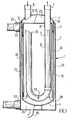
- the anti-blow bottle (1) shown in FIG. 1 comprises a cylindrical envelope (2) constituted by a side wall (3) and, a lower end (4) and an upper end (5).
- the two ends (4) and (5) are spherical caps.
- the upper end (5) is provided with an inlet manifold (6) and an outlet manifold (7).
- the intake manifold (6) opens slightly below the end (5) at which it is welded in (12).
- the outlet pipe (7) has a cylindrical upper part (8) which opens to the outside and a lower part (9) which has the shape of a U.
- the branch (10) of the U is located substantially opposite opposite the tubing (6) but opens at a much lower level.
- the end (11) is connected to the cylindrical upper part (8).
- An internal skirt (15) is placed inside the envelope (2). It comprises a side wall (16) and an upper wall (17) provided with an orifice (18) for the passage of the tube (8).
- the skirt (15) and the envelope (2) define an annular volume (20), an upper dome (27) and a lower dome (26).
- An outer envelope (30) surrounds the assembly. It is connected to the upper part of the side wall (13) of the envelope (2) by an annular ring (31). It includes an intake manifold (32) and an outlet manifold (33) for the exhaust gases from the compressor drive motor.
- the envelope (30) and the envelope (2) define an external annular volume (35) and a lower external dome (36). The spacing between the two envelopes is maintained by the series of centering studs (37), (38), (39).
- the device (1) according to the invention is placed in a heat pump as shown diagrammatically in FIG. 3 in which the evaporator (40), the compressor (41), the condenser (42) and the pressure reducer ( 46), the compressor (41) is rotated by the heat engine (43) whose exhaust gases are sent into the pipe (32) through the pipe (33).
- the compressor drive is shown in (45).
- the regulator (46) is a thermostatic regulator with external pressure equalization. It is adjusted according to a T so as to allow the refrigerant in the evaporator to overheat.
- This device works in the following way: in normal mode, that is to say outside of transient modes the refrigerant gas passes, leaving the evaporator, in the anti-blow bottle (1) where it is overheated before to be introduced into the compressor (41).
- the gas is introduced into the upper dome (21) and then into the annular volume (20) which constitutes the zone of exchange with the exhaust gas introduced by the pipe (32), the two gases being separated by the envelope (2) of the anti-blow bottle, which thus constitutes the exchange surface of the exchanger.
- the annular volume (20) constitutes an acceleration zone where the speed of the gas becomes sufficient to obtain the desired heat exchange, contrary to what happens in the anti-blow bottles of the prior art which do not have an inner skirt. During this normal regime, the gas overheats to rid it of the fine droplets of liquid it contains.
- the exhaust gases are introduced through the tubing (32) into the dome (36) and then collected in the upper part by the tubing (33).
- Tubing (33) and (32) are tangential to the outer casing.
- the device according to the invention has the advantage of cooling the exhaust gases and condensing the vapors therein.
- the device shown in FIG. 1 comprises a tube (60) for discharging the condensates.
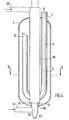
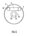
- FIG. 4 and 5 an alternative embodiment of the anti-blow bottle according to the invention. It usually comprises a cylindrical casing (2) and a refrigerant gas outlet pipe (7) comprising a first vertical branch (8), a central U-shaped part (9) and a second vertical branch (10 ).
- a circulation tube (50) of hot gases from the engine passes right through the cylindrical envelope, along its vertical axis, the inlet orifice (51) being located in the lower part (52).
- the refrigerating gas is introduced via the annular pipe (55) defined by the tube (56) which surrounds the tube (50) for circulation of the hot gases.
- the tube (56) is provided in the upper part with an intake manifold (60) situated outside the casing (2) and open in its lower end (61) at a level below the lower level of the central U-shaped part of the tubing (7).
- the exhaust gas circulation tube (50) is provided in its lower end (52) with an orifice (65) for discharging the condensates.
- the gas-gas heat exchange wall is formed by the wall of the tube (50) located opposite the tube (56) while the annular gas acceleration zone is defined by the tube (50) for circulation of the hot gases and by the tube (56) for introducing the refrigerating gas.
- the invention is not limited to the embodiments described. On the contrary, it encompasses all variants, in particular, with regard to the shape of the anti-blow bottle which can, for example, be a capillary system.
Landscapes
- Engineering & Computer Science (AREA)
- Chemical & Material Sciences (AREA)
- Analytical Chemistry (AREA)
- Power Engineering (AREA)
- Physics & Mathematics (AREA)
- Mechanical Engineering (AREA)
- Thermal Sciences (AREA)
- General Engineering & Computer Science (AREA)
- Heat-Exchange Devices With Radiators And Conduit Assemblies (AREA)
- Lubrication Details And Ventilation Of Internal Combustion Engines (AREA)
Applications Claiming Priority (2)
| Application Number | Priority Date | Filing Date | Title |
|---|---|---|---|
| FR8314795 | 1983-09-16 | ||
| FR8314795A FR2552212B1 (fr) | 1983-09-16 | 1983-09-16 | Procede et dispositif de surchauffe d'un fluide frigorifique |
Publications (2)
| Publication Number | Publication Date |
|---|---|
| EP0143013A2 true EP0143013A2 (de) | 1985-05-29 |
| EP0143013A3 EP0143013A3 (de) | 1986-01-08 |
Family
ID=9292293
Family Applications (1)
| Application Number | Title | Priority Date | Filing Date |
|---|---|---|---|
| EP84401814A Withdrawn EP0143013A3 (de) | 1983-09-16 | 1984-09-13 | Verfahren und Vorrichtung zum Überhitzen eines Kühlmittels |
Country Status (6)
| Country | Link |
|---|---|
| US (1) | US4653282A (de) |
| EP (1) | EP0143013A3 (de) |
| JP (1) | JPS6091164A (de) |
| ES (1) | ES8603059A1 (de) |
| FR (1) | FR2552212B1 (de) |
| PT (1) | PT79198B (de) |
Cited By (2)
| Publication number | Priority date | Publication date | Assignee | Title |
|---|---|---|---|---|
| WO1987005381A1 (en) * | 1986-03-03 | 1987-09-11 | Ecr Technologies, Inc. | Fluid flow control system |
| EP0240811A1 (de) * | 1986-04-10 | 1987-10-14 | Hiross International Corporation S.A. | Regelsystem für Anlagen mit einem Kältemittelkreislauf mit Kapillarrohrentspannung |
Families Citing this family (14)
| Publication number | Priority date | Publication date | Assignee | Title |
|---|---|---|---|---|
| US5282370A (en) * | 1992-05-07 | 1994-02-01 | Fayette Tubular Technology Corporation | Air-conditioning system accumulator and method of making same |
| US5471854A (en) * | 1994-06-16 | 1995-12-05 | Automotive Fluid Systems, Inc. | Accumulator for an air conditioning system |
| US5787728A (en) * | 1997-01-21 | 1998-08-04 | Carrier Corporation | Suction accumulator destratifier |
| US6026655A (en) * | 1997-02-27 | 2000-02-22 | Parker-Hannifin Corporation | Liquid accumulator with inlet tube |
| DE19813673B4 (de) * | 1998-03-27 | 2004-01-29 | Daimlerchrysler Ag | Verfahren und Vorrichtung zum Heizen und Kühlen eines Nutzraumes eines Kraftfahrzeuges |
| JP3894701B2 (ja) * | 2000-03-22 | 2007-03-22 | 株式会社ケーヒン | 空調用冷媒受液器 |
| DE10348141B3 (de) * | 2003-10-09 | 2005-02-03 | Visteon Global Technologies, Inc., Dearborn | Innerer Wärmeübertrager für Hochdruckkältemittel mit Akkumulator |
| US20050081559A1 (en) * | 2003-10-20 | 2005-04-21 | Mcgregor Ian A.N. | Accumulator with pickup tube |
| US7559210B2 (en) * | 2005-06-29 | 2009-07-14 | Intel Corporation | Method and apparatus for cooling a heat source |
| JP5019822B2 (ja) * | 2005-08-19 | 2012-09-05 | モーディーン・マニュファクチャリング・カンパニー | 中間の蒸気過熱経路を備える水蒸発器 |
| US20090323276A1 (en) * | 2008-06-25 | 2009-12-31 | Mongia Rajiv K | High performance spreader for lid cooling applications |
| CN102721238A (zh) * | 2012-06-29 | 2012-10-10 | 赵良全 | 自身中冷转换器及使用该转换器的制冷系统及冷凝方法 |
| CN106440573B (zh) * | 2016-09-30 | 2019-02-26 | 青岛海信日立空调系统有限公司 | 一种热泵系统用气液分离器及其制作方法 |
| US11460225B2 (en) * | 2017-06-23 | 2022-10-04 | Jack D. Dowdy, III | Power saving apparatuses for refrigeration |
Family Cites Families (17)
| Publication number | Priority date | Publication date | Assignee | Title |
|---|---|---|---|---|
| FR754234A (de) * | 1933-11-02 | |||
| GB323196A (en) * | 1928-09-21 | 1929-12-23 | Max Schlawe | Improvements in or relating to air heating devices utilising exhaust gases from internal combustion engines |
| GB376713A (en) * | 1930-01-13 | 1932-07-14 | Jean Sabatier | Improvements in or relating to devices for utilizing the heat content from the cooling water and/or exhaust gases of heat engines |
| US2647377A (en) * | 1949-01-24 | 1953-08-04 | Day & Night Mfg Company | Apparatus for providing gravity flow in flooded coil refrigeration systems |
| US3420071A (en) * | 1967-03-10 | 1969-01-07 | Edward W Bottum | Suction accumulator |
| US3421339A (en) * | 1967-05-31 | 1969-01-14 | Trane Co | Unidirectional heat pump system |
| US3766748A (en) * | 1969-07-11 | 1973-10-23 | Chrysler Corp | Vehicle air conditioning system with suction accumulator |
| US3621673A (en) * | 1969-12-08 | 1971-11-23 | Trane Co | Air-conditioning system with combined chiller and accumulator |
| US3803865A (en) * | 1972-06-20 | 1974-04-16 | Borg Warner | Refrigeration control system |
| US4208887A (en) * | 1979-01-22 | 1980-06-24 | Tecumseh Products Company | Suction accumulator having heat exchanger |
| US4236381A (en) * | 1979-02-23 | 1980-12-02 | Intertherm Inc. | Suction-liquid heat exchanger having accumulator and receiver |
| US4217765A (en) * | 1979-06-04 | 1980-08-19 | Atlantic Richfield Company | Heat exchanger-accumulator |
| DE2930404A1 (de) * | 1979-07-26 | 1981-03-12 | 1000 Berlin Erich Schultze KG | Versorgungs- und schutzeinrichtung fuer kaelteanlagen. |
| DE3034965C2 (de) * | 1980-09-17 | 1983-05-05 | Wieland-Werke Ag, 7900 Ulm | Wärmeübertragungseinrichtung für Wärmepumpen |
| DE3206967A1 (de) * | 1982-02-26 | 1983-09-08 | Bedia Maschinenfabrik Verwaltungs-GmbH, 5300 Bonn | Durch eine verbrennungskraftmaschine angetriebene waermepumpe |
| DE3222406C2 (de) * | 1982-06-15 | 1985-07-18 | H. Krantz Gmbh & Co, 5100 Aachen | Verfahren zur Wärmerückgewinnung |
| US4517799A (en) * | 1983-03-09 | 1985-05-21 | Misawa Home Co., Ltd. | Heat utilizing system using internal combustion engine |
-
1983
- 1983-09-16 FR FR8314795A patent/FR2552212B1/fr not_active Expired
-
1984
- 1984-09-11 ES ES535815A patent/ES8603059A1/es not_active Expired
- 1984-09-13 PT PT79198A patent/PT79198B/pt unknown
- 1984-09-13 EP EP84401814A patent/EP0143013A3/de not_active Withdrawn
- 1984-09-14 US US06/651,216 patent/US4653282A/en not_active Expired - Fee Related
- 1984-09-14 JP JP59191911A patent/JPS6091164A/ja active Pending
Cited By (2)
| Publication number | Priority date | Publication date | Assignee | Title |
|---|---|---|---|---|
| WO1987005381A1 (en) * | 1986-03-03 | 1987-09-11 | Ecr Technologies, Inc. | Fluid flow control system |
| EP0240811A1 (de) * | 1986-04-10 | 1987-10-14 | Hiross International Corporation S.A. | Regelsystem für Anlagen mit einem Kältemittelkreislauf mit Kapillarrohrentspannung |
Also Published As
| Publication number | Publication date |
|---|---|
| FR2552212B1 (fr) | 1986-03-21 |
| US4653282A (en) | 1987-03-31 |
| ES535815A0 (es) | 1985-12-01 |
| FR2552212A1 (fr) | 1985-03-22 |
| JPS6091164A (ja) | 1985-05-22 |
| EP0143013A3 (de) | 1986-01-08 |
| PT79198A (fr) | 1984-10-01 |
| PT79198B (fr) | 1986-07-17 |
| ES8603059A1 (es) | 1985-12-01 |
Similar Documents
| Publication | Publication Date | Title |
|---|---|---|
| EP0143013A2 (de) | Verfahren und Vorrichtung zum Überhitzen eines Kühlmittels | |
| LU83555A1 (fr) | Moteur thermique rotatif,son procede de commande,et ensemble d'elements destines a former un tel moteur par transformation d'un moteur existant | |
| EP2580458B1 (de) | Wärmetauschender zylinderkopf | |
| EP0165848A1 (de) | Verfahren zur Erzeugung von Wärme und/oder Kälte mittels einer Kompressionsmaschine mit einem Gemisch als Arbeitsmedium | |
| EP3747522A1 (de) | Destilliervorrichtung, die einen reduzierten energieverbrauch aufweist | |
| FR2769354A1 (fr) | Procede et installation de remplissage d'un reservoir sous pression | |
| EP0425368B1 (de) | Von Gravitationswärmerohren gesteuerte Vorrichtungen zur Erzeugung von Kälte und/oder Wärme mittels einer Reaktion zwischen einem festen Körper und einem Gas | |
| JPS5817361B2 (ja) | 炭化水素の接触燃焼を使つた蒸気用か高温水用かのボイラ | |
| EP0145515A1 (de) | Vervollkommnung einer Installation zur Erwärmung eines Fluidums, bestehend aus einem mit einer Absorptionswärmepumpe verbundenen Zyklus | |
| FR2963416A1 (fr) | Condenseur pour chauffe-eau thermodynamique | |
| FR2482710A1 (fr) | Dispositif fonctionnant de facon parallele et bivalente en tant que pompe a chaleur a absorbeur et chaudiere, pour l'echauffement d'un fluide caloporteur | |
| FR3096901A1 (fr) | Dispositif de distillation présentant une consommation énergétique réduite | |
| FR3122707A1 (fr) | Appareil et procédé de compression de fluide cryogénique. | |
| EP0150647B1 (de) | Kaltfalle zur Reinigung von Verunreinigungen umfassendem flüssigem Natrium | |
| FR2853399A1 (fr) | Echangeur de chaleur helicoidal et chaudiere equipee d'un tel echangeur | |
| FR1465047A (fr) | Appareil réfrigérant | |
| FR3097037A1 (fr) | Dispositif de distillation comportant un système de refroidissement amélioré | |
| FR2693542A1 (fr) | Réacteur de machine frigorifique chimique ou à adsorption solide/gaz. | |
| EP1451463B1 (de) | Thermostatregler für eine brennkraftmaschine mit wasserkühlung | |
| FR2526916A1 (fr) | Soupape a blocage thermique | |
| EP0517578A1 (de) | Wärmetauscher | |
| RU2182989C2 (ru) | Вымораживающая ловушка | |
| FR2800856A1 (fr) | Chaudiere de chauffage du type vertical | |
| FR2618214A1 (fr) | Groupes autonomes de transferts de chaleur. | |
| EP3187795B1 (de) | Kondensationsheizkessel mit doppelter rückführung |
Legal Events
| Date | Code | Title | Description |
|---|---|---|---|
| PUAI | Public reference made under article 153(3) epc to a published international application that has entered the european phase |
Free format text: ORIGINAL CODE: 0009012 |
|
| 17P | Request for examination filed |
Effective date: 19840917 |
|
| AK | Designated contracting states |
Designated state(s): AT BE CH DE FR GB IT LI LU NL SE |
|
| PUAL | Search report despatched |
Free format text: ORIGINAL CODE: 0009013 |
|
| AK | Designated contracting states |
Designated state(s): AT BE CH DE FR GB IT LI LU NL SE |
|
| 17Q | First examination report despatched |
Effective date: 19860805 |
|
| STAA | Information on the status of an ep patent application or granted ep patent |
Free format text: STATUS: THE APPLICATION HAS BEEN WITHDRAWN |
|
| 18W | Application withdrawn |
Withdrawal date: 19870918 |
|
| RIN1 | Information on inventor provided before grant (corrected) |
Inventor name: GUENEAU, MICHEL |