EP0143035B1 - Vorrichtung zur Verankerung von Sicherheitselementen an Aussenwänden von Gebäuden und Gebäude, bei denen diese Vorrichtung an mindestens einer Aussenwand angebracht ist - Google Patents
Vorrichtung zur Verankerung von Sicherheitselementen an Aussenwänden von Gebäuden und Gebäude, bei denen diese Vorrichtung an mindestens einer Aussenwand angebracht ist Download PDFInfo
- Publication number
- EP0143035B1 EP0143035B1 EP84402139A EP84402139A EP0143035B1 EP 0143035 B1 EP0143035 B1 EP 0143035B1 EP 84402139 A EP84402139 A EP 84402139A EP 84402139 A EP84402139 A EP 84402139A EP 0143035 B1 EP0143035 B1 EP 0143035B1
- Authority
- EP
- European Patent Office
- Prior art keywords
- lug
- assembly
- sheath
- wall
- oblong hole
- Prior art date
- Legal status (The legal status is an assumption and is not a legal conclusion. Google has not performed a legal analysis and makes no representation as to the accuracy of the status listed.)
- Expired
Links
- 238000004873 anchoring Methods 0.000 title claims abstract description 31
- 238000010276 construction Methods 0.000 title description 7
- 230000000295 complement effect Effects 0.000 claims abstract description 5
- XEEYBQQBJWHFJM-UHFFFAOYSA-N Iron Chemical compound [Fe] XEEYBQQBJWHFJM-UHFFFAOYSA-N 0.000 description 4
- 239000002184 metal Substances 0.000 description 3
- 229910052751 metal Inorganic materials 0.000 description 3
- 239000004570 mortar (masonry) Substances 0.000 description 3
- 229910000831 Steel Inorganic materials 0.000 description 2
- 238000009415 formwork Methods 0.000 description 2
- 238000009413 insulation Methods 0.000 description 2
- 229910052742 iron Inorganic materials 0.000 description 2
- 229920003023 plastic Polymers 0.000 description 2
- 239000004033 plastic Substances 0.000 description 2
- 238000007789 sealing Methods 0.000 description 2
- 239000010959 steel Substances 0.000 description 2
- 230000004308 accommodation Effects 0.000 description 1
- 238000004026 adhesive bonding Methods 0.000 description 1
- 238000005266 casting Methods 0.000 description 1
- 230000006866 deterioration Effects 0.000 description 1
- 238000006073 displacement reaction Methods 0.000 description 1
- 238000012423 maintenance Methods 0.000 description 1
- 239000000463 material Substances 0.000 description 1
- 230000003647 oxidation Effects 0.000 description 1
- 238000007254 oxidation reaction Methods 0.000 description 1
- 230000035515 penetration Effects 0.000 description 1
- 229920000915 polyvinyl chloride Polymers 0.000 description 1
- 239000004800 polyvinyl chloride Substances 0.000 description 1
- 230000003014 reinforcing effect Effects 0.000 description 1
- 229910001220 stainless steel Inorganic materials 0.000 description 1
- 239000010935 stainless steel Substances 0.000 description 1
- 238000003466 welding Methods 0.000 description 1
Images


Classifications
-
- E—FIXED CONSTRUCTIONS
- E04—BUILDING
- E04G—SCAFFOLDING; FORMS; SHUTTERING; BUILDING IMPLEMENTS OR AIDS, OR THEIR USE; HANDLING BUILDING MATERIALS ON THE SITE; REPAIRING, BREAKING-UP OR OTHER WORK ON EXISTING BUILDINGS
- E04G5/00—Component parts or accessories for scaffolds
- E04G5/04—Means for fastening, supporting, or bracing scaffolds on or against building constructions
- E04G5/046—Means for fastening, supporting, or bracing scaffolds on or against building constructions for fastening scaffoldings on walls
Definitions
- the invention relates to a device for anchoring security elements to the external walls of a construction. It also relates to constructions in at least one of the walls of which at least one such anchoring device is provided.
- the safety rules recommend to the owners to reserve in the walls anchoring means which can be used quickly but which also will remain reusable later in order to reinforce the safety of execution as well of new works as of maintenance works.
- the anchoring devices known to date include permanently fixed in the wall:
- the metal rods sealed directly in the wall have their heads which form an unsightly projection on the facade and have their bodies which create a thermal bridge between the external and internal walls of the wall, ruining the insulation efforts.
- an anchoring device of the type mentioned above comprising, on the one hand, a tab, the so-called front end of which has at least one means for attaching an element of security and, on the other hand, an assembly with which it is associated by means of relative guidance of its movement between two extreme positions in one of which the so-called front end of the tab leaves the assembly to protrude on the face of the wall while in the other it disappears on the whole, this tab and this assembly further comprising abutment faces cooperating with each other to limit the exit of the tab such as for example the faces, one of the 'aforementioned set and the other of a heel carried by the rear part of the tab.
- the subject of the invention is such an anchoring device, in particular characterized in that the means for guiding and abutting the tab in its movement comprise:
- an oblong light oriented longitudinally, perpendicular to the face of the wall
- this light and this orifice being arranged so as to leave a passage for an anchor rod which will pass through the orifice of the sheath as well as the oblong light of the tab and will describe said oblong light during displacement of said tab between its two extreme positions.
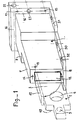
- the anchoring device comprises, on the one hand, a tab 1 of which a so-called front end has at least one means 4, 5 for attaching a security element (not shown) and, on the other hand, an assembly 33 with which it is associated by a means for guiding its movement between two extreme positions in one of which the so-called front end of the tab leaves the assembly to protrude on the face of the wall 2 while in the other it disappears in the assembly 33, this lug 1 and this assembly 33 further comprising abutment faces 6 cooperating with each other to limit the exit of the lug 1.
- This lug comprises a body 3 which preferably is in the form of a rectilinear flat with a longitudinal axis perpendicular to the face of the wall 2 in which the anchoring is carried out, but, in an alternative embodiment, it may consist of: 'a fraction of a crown whose tangent is substantially perpendicular to the wall 2, or a flat articulated about a horizontal axis to the face of the wall.
- This tab 1 has at its front end at least one anchoring means 4, 5 for a safety device such as a bore (4) receiving a heald (not shown) and / or a bore (5) receiving a carabiner of a individual safety device (not shown).
- a safety device such as a bore (4) receiving a heald (not shown) and / or a bore (5) receiving a carabiner of a individual safety device (not shown).
- the body carries a stop such, in a known manner from the prior art, a heel 6 forming a projection on at least one of its faces (FIGS. 1, 2, 3 and 4).
- the tab is made of metal and preferably of stainless steel in the mass.
- the heel 6 can be added by welding or be obtained by folding at ninety degrees from the end of the body.
- the assembly 33 receiving this lug 1 comprises a sheath 7.
- the sheath 7 has a section complementary to that of the body 3 in which sheath, the body 3 of this lug 1 is guided in rectilinear or curved translation.
- the heel 6 cannot therefore enter this sheath 7.
- the housing 8 is connected to the rear end of the sheath 7.
- the rear of the housing has an opening to allow engagement of the tab.
- this opening is closed by a fixed plug 9 by any known means and for example by screwing or gluing.
- the front end of the tab has a shape which facilitates gripping when its output must be ordered.
- this shape will consist of cutouts 10 from the front of the tab thus allowing the fingers to be engaged in the sheath and to grasp this end.
- a flap 12 is hinged around an axis 13.
- This flap 12 may bear a mark which, after the anchoring device has been sealed in the wall, will signal the existence of the anchoring point to the owner and / or to businesses.
- This anchoring device is preferably sealed in the wall as soon as it is built, but it can still be later.
- the front end of the sheath will have threaded holes 14 with axes substantially perpendicular to the wall 2 and receiving screws passing through holes made in good place in the form.
- smooth or threaded holes 15 with axes substantially perpendicular to the wall 2 may be provided at the rear end.
- These holes may be made in the thickness of the walls of the housing 8 or, preferably, in a flange 16 of said housing providing a base.
- This extension may, for this purpose, be telescopic. Its fixing can be done by screwing in the threaded holes 14 already provided at the front of the sleeve for fixing to the formwork.
- the front of the extension has a transverse bore 18 allowing the engagement of the axis 13 of articulation of the flap 12 mentioned above.
- This arrangement could be used when the wall 2 includes, in front of a sheeted web 19, a facing 20, with the interposition of insulation 21.
- the length of the leg 1 is obviously a function of the use of the sheath alone or in combination with an extension.
- the base 16 may also have a transverse bore 22 for engaging a concrete reinforcing iron or a steel wire for ligating the device to a frame.
- This base may also have holes 23 with an axis perpendicular to its plane and called to receive rods 24 for connection to a counter plate 25 distributing the force over a larger surface.
- this counterplate To be connected to a temporary anchorage until the concrete sets or hardening of the masonry mortar, this counterplate has a means 26 for fixing a screw such as a nut 27 welded on its rear face coaxially to a bore 28 of said counter-plate 25.
- a cover 29 may be placed in front of the nut 27.
- the sheath and the housing may also have at their base a flange 30, 31 pierced with wide holes 32 increasing the anchoring by penetration of the concrete or the mortar possibly supplemented with passages of steel wires.
- edges will be of thickness determined so as to allow their accommodation in a masonry joint. For example, they will be ten millimeters thick and twenty millimeters wide.
- the assembly 33 formed by the sheath, the housing and the plug as well as the flap will advantageously be molded from plastic material and for example from polyvinyl chloride.
- Against the plate 25 itself has holes 34 by which it can be fixed to a formwork.
- the plastic may be tinted or painted so as to merge with the facing. During use, it suffices to open the flap 12 and take out the tab 1 to have an anchoring.
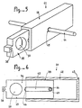
- the anchoring device comprises a lug 35, the body 36 of which preferably has the shape of a straight flat with a longitudinal axis perpendicular to the face of the wall in which the anchoring is made.
- the front end of the lug 35 has at least one anchoring means for a safety device, and in particular an orifice 37 capable of receiving a heald and a bore 38 in particular for a carabiner of a device individual security.
- the rear part 39 of the body 36 of the tab 35 has an oblong slot 40, oriented longitudinally, perpendicular to the face of the wall in which the device is intended to be anchored.
- the assembly 41 receiving the tab 35 comprises a sheath 42, of internal section complementary to that of the body of the tab 35, and of length at least equal to that of the tab.
- the rear end 43 of the sleeve 42 is preferably closed, and this closure is achieved by any suitable means, and for example by a wall secured to the sleeve or by an attached plug.
- the sleeve 42 is traversed right through, transversely by an anchor rod 44 which is for example constituted by a concrete iron.
- the sheath 42 has orifices 45 for the passage of this anchor rod 44 which is located, as can be seen in FIG. 6, at the level of the opening 40 of the tab 35, so that the rod d anchoring passes through the sheath 42 and the body 36 of the tab 35 inside said lumen 40.
- the orifices 45 on the side walls of the sleeve 42 and the lumen 40 of the body 36 of the tab 35 are respectively positioned and dimensioned so as to allow the movement of the tab 35 between two extreme positions in one of which the so-called front end of the lug 35 leaves the assembly to project from the face of the wall, while in the other, it disappears in the assembly 41.
- the anchor rod 44 also makes it possible to seal the assembly 41 and the lug 35 in a wall, this sealing of the sleeve 42 may moreover be reinforced by any known complementary anchoring means.
- a flap or a plug advantageously closes the front face of the sheath 42 when the tab 35 is in the retracted position.
- the rear end of the sleeve 41 may have a base and positioning means for the anchoring device similar to those which have been previously described.
- the front part could also have an extension such as the previous screwed extension.
Landscapes
- Engineering & Computer Science (AREA)
- Architecture (AREA)
- Mechanical Engineering (AREA)
- Civil Engineering (AREA)
- Structural Engineering (AREA)
- Joining Of Building Structures In Genera (AREA)
- Working Measures On Existing Buildindgs (AREA)
Claims (8)
Priority Applications (1)
| Application Number | Priority Date | Filing Date | Title |
|---|---|---|---|
| AT84402139T ATE43148T1 (de) | 1983-11-23 | 1984-10-24 | Vorrichtung zur verankerung von sicherheitselementen an aussenwaenden von gebaeuden und gebaeude, bei denen diese vorrichtung an mindestens einer aussenwand angebracht ist. |
Applications Claiming Priority (2)
| Application Number | Priority Date | Filing Date | Title |
|---|---|---|---|
| FR8318967A FR2555228B1 (fr) | 1983-11-23 | 1983-11-23 | Dispositif d'ancrage d'elements de securite aux parois exterieures d'une construction et constructions dans au moins l'une des parois desquelles est prevu un tel dispositif |
| FR8318967 | 1983-11-23 |
Publications (3)
| Publication Number | Publication Date |
|---|---|
| EP0143035A2 EP0143035A2 (de) | 1985-05-29 |
| EP0143035A3 EP0143035A3 (en) | 1986-06-25 |
| EP0143035B1 true EP0143035B1 (de) | 1989-05-17 |
Family
ID=9294605
Family Applications (1)
| Application Number | Title | Priority Date | Filing Date |
|---|---|---|---|
| EP84402139A Expired EP0143035B1 (de) | 1983-11-23 | 1984-10-24 | Vorrichtung zur Verankerung von Sicherheitselementen an Aussenwänden von Gebäuden und Gebäude, bei denen diese Vorrichtung an mindestens einer Aussenwand angebracht ist |
Country Status (4)
| Country | Link |
|---|---|
| EP (1) | EP0143035B1 (de) |
| AT (1) | ATE43148T1 (de) |
| DE (1) | DE3478234D1 (de) |
| FR (1) | FR2555228B1 (de) |
Families Citing this family (9)
| Publication number | Priority date | Publication date | Assignee | Title |
|---|---|---|---|---|
| DE9217689U1 (de) * | 1992-12-24 | 1993-04-01 | Lutz Ankersysteme GmbH & Co KG, 6980 Wertheim | Verankerungsvorrichtung für Gerüste |
| ES2272136B1 (es) * | 2004-12-01 | 2008-04-16 | Jose Ramon Guinart Pallares | Sistema de seguridad integral aplicable a construcciones. |
| ES2288080B1 (es) * | 2005-07-22 | 2008-08-16 | Vicorgilta, S.L. | Sistema de anclajes de seguridad para la construccion de edificios. |
| NO325802B1 (no) * | 2006-09-04 | 2008-07-21 | Jan Martin Kleppe | Anordning ved lopeskinne |
| WO2010139004A1 (en) * | 2009-06-02 | 2010-12-09 | Roofsafe-T-Systems Pty Limited | Anchor |
| NL2004502C2 (nl) * | 2010-04-02 | 2011-10-04 | Jeroen Geerts | Inrichting en werkwijze voor het bevestigen van stelelementen. |
| JP5934013B2 (ja) * | 2012-04-05 | 2016-06-15 | ヒロセ株式会社 | 補強土壁の足場構造及びその設置治具 |
| NL2011700C2 (nl) * | 2012-12-21 | 2014-06-24 | J W Fransen Beheer B V | Verbeterd stelsysteem voor een metselprofiel. |
| IT202300022524A1 (it) * | 2023-10-26 | 2025-04-26 | Vetreria Tacca Srl | Dispositivo di ancoraggio per linea vita su parapetti in vetro |
Family Cites Families (4)
| Publication number | Priority date | Publication date | Assignee | Title |
|---|---|---|---|---|
| DE226362C (de) * | ||||
| FR466605A (fr) * | 1913-12-24 | 1914-05-19 | Emil Schaerer | échafaudage |
| CH100889A (de) * | 1922-02-04 | 1923-08-16 | Schweizerische Geruestgesellsc | Baugerüst. |
| GB1435689A (en) * | 1972-02-01 | 1976-05-12 | Lecormex Ltd | Device for securing scaffolding to building constructions |
-
1983
- 1983-11-23 FR FR8318967A patent/FR2555228B1/fr not_active Expired
-
1984
- 1984-10-24 AT AT84402139T patent/ATE43148T1/de not_active IP Right Cessation
- 1984-10-24 EP EP84402139A patent/EP0143035B1/de not_active Expired
- 1984-10-24 DE DE8484402139T patent/DE3478234D1/de not_active Expired
Also Published As
| Publication number | Publication date |
|---|---|
| DE3478234D1 (en) | 1989-06-22 |
| ATE43148T1 (de) | 1989-06-15 |
| FR2555228A1 (fr) | 1985-05-24 |
| EP0143035A2 (de) | 1985-05-29 |
| EP0143035A3 (en) | 1986-06-25 |
| FR2555228B1 (fr) | 1986-03-28 |
Similar Documents
| Publication | Publication Date | Title |
|---|---|---|
| EP0143035B1 (de) | Vorrichtung zur Verankerung von Sicherheitselementen an Aussenwänden von Gebäuden und Gebäude, bei denen diese Vorrichtung an mindestens einer Aussenwand angebracht ist | |
| EP0628695B1 (de) | Verschlusseinrichtung für die Leiter eines Rolladenkastens | |
| FR2459192A1 (fr) | Poignee pour outil manuel | |
| FR2935450A1 (fr) | Etrier pour la fixation d'une barre sur un montant | |
| FR2915500A1 (fr) | Garde-corps. | |
| EP0546971B1 (de) | Unsichtbare Verbindungsvorrichtung, insbesondere anwendbar für gespannte Leinwände | |
| EP0216683B1 (de) | Ein Magazin bildendes Werkzeug zum Anbringen irgend eines Artikels, insbesondere für Verkabelungskennzeichnungen | |
| EP1842986A1 (de) | Schutzgatter, das sich aus mit Gelenken versehenen Bauelementen zusammensetzt | |
| EP0141730B1 (de) | Verankerungsvorrichtung für Geräte bei Dacharbeiten | |
| FR2483992A1 (fr) | Fermeture de plinthe pour un revetement mural vertical et procede de mise en place de ce revetement | |
| FR2718918A1 (fr) | Unité de commande. | |
| EP1607551A1 (de) | Befestigungselement für ein Zaungitter an einem Pfosten und mit einem solchen Element hergestellter Zaun | |
| EP0010820B1 (de) | Kasten für elektrische Geräte | |
| FR3005678A1 (fr) | Armature pour coffre de volet | |
| EP1114911B1 (de) | Endverschlusskappe für Rolladenkasten | |
| FR2597920A1 (fr) | Dispositif permettant d'accrocher et de deplacer une echelle sur un toit, et echelle munie de ses elements | |
| FR2766223A1 (fr) | Dispositif permettant d'assurer la protection du personnel travaillant sur les toitures | |
| FR2877980A1 (fr) | Dispositif de verrouillage pour portillon d'acces a une zone securisee notamment une piscine | |
| FR2831913A1 (fr) | Dispositif de verrouillage/deverrouillage multi-penes pour ouvrant coulissant | |
| FR2891298A1 (fr) | Arret de volet comportant un blocage reglable | |
| FR2672115A3 (fr) | Poignee interne de commande d'une porte coulissante pour chambres frigorifiques. | |
| FR2738582A1 (fr) | Bras de deploiement pour store et ensemble formant store | |
| FR2599778A1 (fr) | Dispositif de montage et d'articulation reglable pour volets et fermetures similaires, adaptable notamment sur un gond | |
| EP1929115A1 (de) | Rolladenanschlag, verfahren zur anordnung des anschlags und damit ausgestatteter rollladen | |
| FR2759859A1 (fr) | Taquet pour cornadis |
Legal Events
| Date | Code | Title | Description |
|---|---|---|---|
| PUAI | Public reference made under article 153(3) epc to a published international application that has entered the european phase |
Free format text: ORIGINAL CODE: 0009012 |
|
| AK | Designated contracting states |
Designated state(s): AT BE CH DE FR GB IT LI LU NL SE |
|
| RTI1 | Title (correction) | ||
| PUAL | Search report despatched |
Free format text: ORIGINAL CODE: 0009013 |
|
| AK | Designated contracting states |
Kind code of ref document: A3 Designated state(s): AT BE CH DE FR GB IT LI LU NL SE |
|
| 17P | Request for examination filed |
Effective date: 19861103 |
|
| 17Q | First examination report despatched |
Effective date: 19880211 |
|
| GRAA | (expected) grant |
Free format text: ORIGINAL CODE: 0009210 |
|
| AK | Designated contracting states |
Kind code of ref document: B1 Designated state(s): AT BE CH DE FR GB IT LI LU NL SE |
|
| REF | Corresponds to: |
Ref document number: 43148 Country of ref document: AT Date of ref document: 19890615 Kind code of ref document: T |
|
| REF | Corresponds to: |
Ref document number: 3478234 Country of ref document: DE Date of ref document: 19890622 |
|
| GBT | Gb: translation of ep patent filed (gb section 77(6)(a)/1977) | ||
| ITF | It: translation for a ep patent filed | ||
| PLBE | No opposition filed within time limit |
Free format text: ORIGINAL CODE: 0009261 |
|
| STAA | Information on the status of an ep patent application or granted ep patent |
Free format text: STATUS: NO OPPOSITION FILED WITHIN TIME LIMIT |
|
| 26N | No opposition filed | ||
| ITTA | It: last paid annual fee | ||
| PGFP | Annual fee paid to national office [announced via postgrant information from national office to epo] |
Ref country code: CH Payment date: 19920922 Year of fee payment: 9 |
|
| PGFP | Annual fee paid to national office [announced via postgrant information from national office to epo] |
Ref country code: AT Payment date: 19921012 Year of fee payment: 9 |
|
| PGFP | Annual fee paid to national office [announced via postgrant information from national office to epo] |
Ref country code: SE Payment date: 19921020 Year of fee payment: 9 |
|
| PGFP | Annual fee paid to national office [announced via postgrant information from national office to epo] |
Ref country code: NL Payment date: 19921031 Year of fee payment: 9 |
|
| PG25 | Lapsed in a contracting state [announced via postgrant information from national office to epo] |
Ref country code: AT Effective date: 19931024 |
|
| PG25 | Lapsed in a contracting state [announced via postgrant information from national office to epo] |
Ref country code: SE Effective date: 19931025 |
|
| PG25 | Lapsed in a contracting state [announced via postgrant information from national office to epo] |
Ref country code: LI Effective date: 19931031 Ref country code: CH Effective date: 19931031 |
|
| EPTA | Lu: last paid annual fee | ||
| PG25 | Lapsed in a contracting state [announced via postgrant information from national office to epo] |
Ref country code: NL Effective date: 19940501 |
|
| NLV4 | Nl: lapsed or anulled due to non-payment of the annual fee | ||
| REG | Reference to a national code |
Ref country code: CH Ref legal event code: PL |
|
| EUG | Se: european patent has lapsed |
Ref document number: 84402139.4 Effective date: 19940510 |
|
| PGFP | Annual fee paid to national office [announced via postgrant information from national office to epo] |
Ref country code: LU Payment date: 19991014 Year of fee payment: 16 Ref country code: BE Payment date: 19991014 Year of fee payment: 16 |
|
| PGFP | Annual fee paid to national office [announced via postgrant information from national office to epo] |
Ref country code: FR Payment date: 19991015 Year of fee payment: 16 |
|
| PGFP | Annual fee paid to national office [announced via postgrant information from national office to epo] |
Ref country code: GB Payment date: 19991020 Year of fee payment: 16 |
|
| PGFP | Annual fee paid to national office [announced via postgrant information from national office to epo] |
Ref country code: DE Payment date: 19991028 Year of fee payment: 16 |
|
| PG25 | Lapsed in a contracting state [announced via postgrant information from national office to epo] |
Ref country code: LU Free format text: LAPSE BECAUSE OF NON-PAYMENT OF DUE FEES Effective date: 20001024 Ref country code: GB Free format text: LAPSE BECAUSE OF NON-PAYMENT OF DUE FEES Effective date: 20001024 |
|
| PG25 | Lapsed in a contracting state [announced via postgrant information from national office to epo] |
Ref country code: BE Free format text: LAPSE BECAUSE OF NON-PAYMENT OF DUE FEES Effective date: 20001031 |
|
| BERE | Be: lapsed |
Owner name: S.A. DUARIB Effective date: 20001031 Owner name: DALLENNES JEAN Effective date: 20001031 Owner name: ETS FOURNIER & CIE S.A.R.L. Effective date: 20001031 |
|
| GBPC | Gb: european patent ceased through non-payment of renewal fee |
Effective date: 20001024 |
|
| PG25 | Lapsed in a contracting state [announced via postgrant information from national office to epo] |
Ref country code: FR Free format text: LAPSE BECAUSE OF NON-PAYMENT OF DUE FEES Effective date: 20010629 |
|
| PG25 | Lapsed in a contracting state [announced via postgrant information from national office to epo] |
Ref country code: DE Free format text: LAPSE BECAUSE OF NON-PAYMENT OF DUE FEES Effective date: 20010703 |
|
| REG | Reference to a national code |
Ref country code: FR Ref legal event code: ST |