EP0143035B1 - Dispositif d'ancrage d'éléments de sécurité aux parois extérieures d'une construction et constructions dans au moins l'une des parois desquelles est prévu un tel dispositif - Google Patents
Dispositif d'ancrage d'éléments de sécurité aux parois extérieures d'une construction et constructions dans au moins l'une des parois desquelles est prévu un tel dispositif Download PDFInfo
- Publication number
- EP0143035B1 EP0143035B1 EP84402139A EP84402139A EP0143035B1 EP 0143035 B1 EP0143035 B1 EP 0143035B1 EP 84402139 A EP84402139 A EP 84402139A EP 84402139 A EP84402139 A EP 84402139A EP 0143035 B1 EP0143035 B1 EP 0143035B1
- Authority
- EP
- European Patent Office
- Prior art keywords
- lug
- assembly
- sheath
- wall
- oblong hole
- Prior art date
- Legal status (The legal status is an assumption and is not a legal conclusion. Google has not performed a legal analysis and makes no representation as to the accuracy of the status listed.)
- Expired
Links
- 238000004873 anchoring Methods 0.000 title claims abstract description 31
- 238000010276 construction Methods 0.000 title description 7
- 230000000295 complement effect Effects 0.000 claims abstract description 5
- XEEYBQQBJWHFJM-UHFFFAOYSA-N Iron Chemical compound [Fe] XEEYBQQBJWHFJM-UHFFFAOYSA-N 0.000 description 4
- 239000002184 metal Substances 0.000 description 3
- 229910052751 metal Inorganic materials 0.000 description 3
- 239000004570 mortar (masonry) Substances 0.000 description 3
- 229910000831 Steel Inorganic materials 0.000 description 2
- 238000009415 formwork Methods 0.000 description 2
- 238000009413 insulation Methods 0.000 description 2
- 229910052742 iron Inorganic materials 0.000 description 2
- 229920003023 plastic Polymers 0.000 description 2
- 239000004033 plastic Substances 0.000 description 2
- 238000007789 sealing Methods 0.000 description 2
- 239000010959 steel Substances 0.000 description 2
- 230000004308 accommodation Effects 0.000 description 1
- 238000004026 adhesive bonding Methods 0.000 description 1
- 238000005266 casting Methods 0.000 description 1
- 230000006866 deterioration Effects 0.000 description 1
- 238000006073 displacement reaction Methods 0.000 description 1
- 238000012423 maintenance Methods 0.000 description 1
- 239000000463 material Substances 0.000 description 1
- 230000003647 oxidation Effects 0.000 description 1
- 238000007254 oxidation reaction Methods 0.000 description 1
- 230000035515 penetration Effects 0.000 description 1
- 229920000915 polyvinyl chloride Polymers 0.000 description 1
- 239000004800 polyvinyl chloride Substances 0.000 description 1
- 230000003014 reinforcing effect Effects 0.000 description 1
- 229910001220 stainless steel Inorganic materials 0.000 description 1
- 239000010935 stainless steel Substances 0.000 description 1
- 238000003466 welding Methods 0.000 description 1
Images


Classifications
-
- E—FIXED CONSTRUCTIONS
- E04—BUILDING
- E04G—SCAFFOLDING; FORMS; SHUTTERING; BUILDING IMPLEMENTS OR AIDS, OR THEIR USE; HANDLING BUILDING MATERIALS ON THE SITE; REPAIRING, BREAKING-UP OR OTHER WORK ON EXISTING BUILDINGS
- E04G5/00—Component parts or accessories for scaffolds
- E04G5/04—Means for fastening, supporting, or bracing scaffolds on or against building constructions
- E04G5/046—Means for fastening, supporting, or bracing scaffolds on or against building constructions for fastening scaffoldings on walls
Definitions
- the invention relates to a device for anchoring security elements to the external walls of a construction. It also relates to constructions in at least one of the walls of which at least one such anchoring device is provided.
- the safety rules recommend to the owners to reserve in the walls anchoring means which can be used quickly but which also will remain reusable later in order to reinforce the safety of execution as well of new works as of maintenance works.
- the anchoring devices known to date include permanently fixed in the wall:
- the metal rods sealed directly in the wall have their heads which form an unsightly projection on the facade and have their bodies which create a thermal bridge between the external and internal walls of the wall, ruining the insulation efforts.
- an anchoring device of the type mentioned above comprising, on the one hand, a tab, the so-called front end of which has at least one means for attaching an element of security and, on the other hand, an assembly with which it is associated by means of relative guidance of its movement between two extreme positions in one of which the so-called front end of the tab leaves the assembly to protrude on the face of the wall while in the other it disappears on the whole, this tab and this assembly further comprising abutment faces cooperating with each other to limit the exit of the tab such as for example the faces, one of the 'aforementioned set and the other of a heel carried by the rear part of the tab.
- the subject of the invention is such an anchoring device, in particular characterized in that the means for guiding and abutting the tab in its movement comprise:
- an oblong light oriented longitudinally, perpendicular to the face of the wall
- this light and this orifice being arranged so as to leave a passage for an anchor rod which will pass through the orifice of the sheath as well as the oblong light of the tab and will describe said oblong light during displacement of said tab between its two extreme positions.
- the anchoring device comprises, on the one hand, a tab 1 of which a so-called front end has at least one means 4, 5 for attaching a security element (not shown) and, on the other hand, an assembly 33 with which it is associated by a means for guiding its movement between two extreme positions in one of which the so-called front end of the tab leaves the assembly to protrude on the face of the wall 2 while in the other it disappears in the assembly 33, this lug 1 and this assembly 33 further comprising abutment faces 6 cooperating with each other to limit the exit of the lug 1.
- This lug comprises a body 3 which preferably is in the form of a rectilinear flat with a longitudinal axis perpendicular to the face of the wall 2 in which the anchoring is carried out, but, in an alternative embodiment, it may consist of: 'a fraction of a crown whose tangent is substantially perpendicular to the wall 2, or a flat articulated about a horizontal axis to the face of the wall.
- This tab 1 has at its front end at least one anchoring means 4, 5 for a safety device such as a bore (4) receiving a heald (not shown) and / or a bore (5) receiving a carabiner of a individual safety device (not shown).
- a safety device such as a bore (4) receiving a heald (not shown) and / or a bore (5) receiving a carabiner of a individual safety device (not shown).
- the body carries a stop such, in a known manner from the prior art, a heel 6 forming a projection on at least one of its faces (FIGS. 1, 2, 3 and 4).
- the tab is made of metal and preferably of stainless steel in the mass.
- the heel 6 can be added by welding or be obtained by folding at ninety degrees from the end of the body.
- the assembly 33 receiving this lug 1 comprises a sheath 7.
- the sheath 7 has a section complementary to that of the body 3 in which sheath, the body 3 of this lug 1 is guided in rectilinear or curved translation.
- the heel 6 cannot therefore enter this sheath 7.
- the housing 8 is connected to the rear end of the sheath 7.
- the rear of the housing has an opening to allow engagement of the tab.
- this opening is closed by a fixed plug 9 by any known means and for example by screwing or gluing.
- the front end of the tab has a shape which facilitates gripping when its output must be ordered.
- this shape will consist of cutouts 10 from the front of the tab thus allowing the fingers to be engaged in the sheath and to grasp this end.
- a flap 12 is hinged around an axis 13.
- This flap 12 may bear a mark which, after the anchoring device has been sealed in the wall, will signal the existence of the anchoring point to the owner and / or to businesses.
- This anchoring device is preferably sealed in the wall as soon as it is built, but it can still be later.
- the front end of the sheath will have threaded holes 14 with axes substantially perpendicular to the wall 2 and receiving screws passing through holes made in good place in the form.
- smooth or threaded holes 15 with axes substantially perpendicular to the wall 2 may be provided at the rear end.
- These holes may be made in the thickness of the walls of the housing 8 or, preferably, in a flange 16 of said housing providing a base.
- This extension may, for this purpose, be telescopic. Its fixing can be done by screwing in the threaded holes 14 already provided at the front of the sleeve for fixing to the formwork.
- the front of the extension has a transverse bore 18 allowing the engagement of the axis 13 of articulation of the flap 12 mentioned above.
- This arrangement could be used when the wall 2 includes, in front of a sheeted web 19, a facing 20, with the interposition of insulation 21.
- the length of the leg 1 is obviously a function of the use of the sheath alone or in combination with an extension.
- the base 16 may also have a transverse bore 22 for engaging a concrete reinforcing iron or a steel wire for ligating the device to a frame.
- This base may also have holes 23 with an axis perpendicular to its plane and called to receive rods 24 for connection to a counter plate 25 distributing the force over a larger surface.
- this counterplate To be connected to a temporary anchorage until the concrete sets or hardening of the masonry mortar, this counterplate has a means 26 for fixing a screw such as a nut 27 welded on its rear face coaxially to a bore 28 of said counter-plate 25.
- a cover 29 may be placed in front of the nut 27.
- the sheath and the housing may also have at their base a flange 30, 31 pierced with wide holes 32 increasing the anchoring by penetration of the concrete or the mortar possibly supplemented with passages of steel wires.
- edges will be of thickness determined so as to allow their accommodation in a masonry joint. For example, they will be ten millimeters thick and twenty millimeters wide.
- the assembly 33 formed by the sheath, the housing and the plug as well as the flap will advantageously be molded from plastic material and for example from polyvinyl chloride.
- Against the plate 25 itself has holes 34 by which it can be fixed to a formwork.
- the plastic may be tinted or painted so as to merge with the facing. During use, it suffices to open the flap 12 and take out the tab 1 to have an anchoring.
- the anchoring device comprises a lug 35, the body 36 of which preferably has the shape of a straight flat with a longitudinal axis perpendicular to the face of the wall in which the anchoring is made.
- the front end of the lug 35 has at least one anchoring means for a safety device, and in particular an orifice 37 capable of receiving a heald and a bore 38 in particular for a carabiner of a device individual security.
- the rear part 39 of the body 36 of the tab 35 has an oblong slot 40, oriented longitudinally, perpendicular to the face of the wall in which the device is intended to be anchored.
- the assembly 41 receiving the tab 35 comprises a sheath 42, of internal section complementary to that of the body of the tab 35, and of length at least equal to that of the tab.
- the rear end 43 of the sleeve 42 is preferably closed, and this closure is achieved by any suitable means, and for example by a wall secured to the sleeve or by an attached plug.
- the sleeve 42 is traversed right through, transversely by an anchor rod 44 which is for example constituted by a concrete iron.
- the sheath 42 has orifices 45 for the passage of this anchor rod 44 which is located, as can be seen in FIG. 6, at the level of the opening 40 of the tab 35, so that the rod d anchoring passes through the sheath 42 and the body 36 of the tab 35 inside said lumen 40.
- the orifices 45 on the side walls of the sleeve 42 and the lumen 40 of the body 36 of the tab 35 are respectively positioned and dimensioned so as to allow the movement of the tab 35 between two extreme positions in one of which the so-called front end of the lug 35 leaves the assembly to project from the face of the wall, while in the other, it disappears in the assembly 41.
- the anchor rod 44 also makes it possible to seal the assembly 41 and the lug 35 in a wall, this sealing of the sleeve 42 may moreover be reinforced by any known complementary anchoring means.
- a flap or a plug advantageously closes the front face of the sheath 42 when the tab 35 is in the retracted position.
- the rear end of the sleeve 41 may have a base and positioning means for the anchoring device similar to those which have been previously described.
- the front part could also have an extension such as the previous screwed extension.
Landscapes
- Engineering & Computer Science (AREA)
- Architecture (AREA)
- Mechanical Engineering (AREA)
- Civil Engineering (AREA)
- Structural Engineering (AREA)
- Joining Of Building Structures In Genera (AREA)
- Working Measures On Existing Buildindgs (AREA)
Description
- L'invention se rapporte à un dispositif d'ancrage d'éléments de sécurité aux parois extérieures d'une construction. Elle se rapporte également aux constructions dans au moins l'une des parois desquelles est prévu au moins un tel dispositif d'ancrage.
- Les règles de sécurité préconisent aux maîtres d'ouvrage de réserver dans les parois des moyens d'ancrage qui soient utilisables rapidement mais qui aussi demeureront réutilisables ultérieurement afin de renforcer la sécurité d'exécution tant de travaux neufs que des travaux d'entretien.
- Les dispositifs d'ancrage connus à ce jour comprennent fixés à demeure dans le mur :
- soit une tige métallique dont une partie est laissée en saillie et présente une tête pour la retenue d'une partie associée au dispositif de sécurité,
- soit en une simple douille dans laquelle se fixe alors temporairement une tige du type précité . que ce soit par goupillage, vissage et/ou expansion.
- Tous ces moyens ont malheureusement de nombreux inconvénients, tels l'impossibilité de leur adaptation à la consistance du mur et la détérioration rapide notamment par oxydation des tiges ou douilles.
- Par ailleurs, les tiges métalliques scellées directement dans le mur ont leur tête qui forme une saillie inesthétique sur la façade et ont leur corps qui crée entre les parois externe et interne du mur un pont thermique ruinant les efforts d'isolation.
- Quant aux douilles recevant des tiges amovibles (FR-A-466.605 figures 1 à 43 et 45 à 53), leur utilisation nécessite pour les entrepreneurs de toujours disposer de tiges parfaitement adaptées à chaque type de douille pouvant être réservée dans les constructions où ils interviennent.
- A également été proposé (FR-A-466.605 figure 44) un dispositif d'ancrage du type cité plus haut comprenant d'une part, une patte dont l'extrémité dite avant présente au moins un moyen d'accrochage d'un élément de sécurité et, d'autre part un ensemble auquel elle est associée par un moyen de relatif guidage de son déplacement entre deux positions extrêmes dans l'une desquelles l'extrémité dite avant de la patte sort de l'ensemble pour venir en saillie sur la face de la paroi alors que dans l'autre elle disparaît dans l'ensemble, cette patte et cet ensemble comprenant en outre des faces de butée coopérant entre elles pour limiter la sortie de la patte telles par exemple les faces, l'une de l'ensemble précité et l'autre d'un talon porté par la partie arrière de la patte.
- A partir de cet état de la technique, un résultat que l'invention vise à obtenir est un tel dispositif d'ancrage dont la patte est simple à monter dans son guidage et dont l'ancrage du boîtier dans la paroi est renforcé.
- Est également un résultat de l'invention, un ancrage avec lequel les efforts retransmis à la paroi sont bien répartis. A cet effet, l'invention a pour objet un tel dispositif d'ancrage notamment caractérisé en ce que le moyen de guidage et de butée de la patte dans son déplacement comprennent :
- dans la patte, une lumière oblongue, orientée longitudinalement, perpendiculairement à la face du mur,
- dans le fourreau de l'ensemble un orifice, cette lumière et cet orifice étant disposés de manière à laisser un passage pour une tige d'ancrage qui traversera l'orifice du fourreau ainsi que la lumière oblongue de la patte et décrira ladite lumière oblongue lors du déplacement de ladite patte entre ses deux positions extrêmes.
- Elle a également pour objet les constructions pourvues de tels dispositifs d'ancrage.
- Elle sera bien comprise à l'aide de la description ci-après faite, à titre d'exemple non limitatif, en regard du dessin ci-annexé qui représente schématiquement :
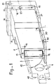
- . figure 1 : le dispositif d'ancrage vu en perspective,
- figure 2 : le dispositif d'ancrage vu en coupe par un plan horizontal,
- figure 3 : une variante de réalisation de l'avant du dispositif,
- figure 4 : une variante de réalisation de l'arrière du dispositif.
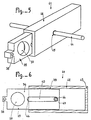
- figure 5 : une autre variante de réalisation vue en perspective,
- figure 6 : le dispositif de la figure 5 en coupe par un plan vertical, orienté longitudinalement.
- En se reportant au dessin, on voit que le dispositif d'ancrage comprend, d'une part, une patte 1 dont une extrémité dite avant présente au moins un moyen 4, 5 d'accrochage d'un élément de sécurité (non représenté) et, d'autre part, un ensemble 33 auquel elle est associée par un moyen de guidage de son déplacement entre deux positions extrêmes dans l'une desquelles l'extrémité dite avant de la patte sort de l'ensemble pour venir en saillie sur la face de la paroi 2 alors que dans l'autre elle disparaît dans l'ensemble 33, cette patte 1 et cet ensemble 33 comprenant en outre des faces de butée 6 coopérant entre elles pour limiter la sortie de la patte 1.
- Cette patte comprend un corps 3 qui de préférence se présente sous la forme d'un plat rectiligne d'axe longitudinal perpendiculaire à la face du mur 2 dans lequel est réalisé l'ancrage mais, dans une variante de réalisation, il peut être constitué d'une fraction de couronne dont la tangente est sensiblement perpendiculaire à la paroi 2, ou d'un plat articulé autour d'un axe horizontal à la face du mur.
- Cette patte 1 présente à son extrémité avant au moins un moyen d'ancrage 4, 5 pour un dispositif de sécurité tel un perçage (4) recevant une lisse (non représentée) et/ou un perçage (5) recevant un mousqueton d'un dispositif individuel de sécurité (non représenté).
- A sa partie arrière, le corps porte une butée telle, de manière connue de l'état de la technique, un talon 6 formant une saillie sur au moins une de ses faces (figures 1, 2, 3 et 4).
- Pour offrir la plus grande résistance, c'est le plus grand côté de la section du plat qui est disposé verticalement. Dans le même but, la patte est réalisée en métal et de préférence en acier inoxydable dans la masse.
- Le talon 6 peut être rapporté par soudure ou être obtenu par rabattement à quatre vingt dix degrés de l'extrémité du corps.
- L'ensemble 33 recevant cette patte 1 comprend un fourreau 7. De préférence, le fourreau 7 a une section complémentaire à celle du corps 3 dans lequel fourreau, le corps 3 de cette patte 1 est guidé en translation rectiligne ou courbe. Le talon 6 ne peut donc pénétrer dans ce fourreau 7. Le boîtier 8 est raccordé à l'extrémité arrière du fourreau 7.
- Il a une section transversale supérieure à celle du corps 3 et de son talon 6 et qui, en outre, a une longueur au moins équivalente à celle de la partie avant du corps pour permettre un déplacement « D » du talon et donc de la patte entre deux positions extrêmes, l'une (représentée en traits mixtes figure 1 et en traits pleins figure 2) où l'extrémité avant est sortie du fourreau pour dégager les moyens d'accrochage 4, 5, l'autre (représentée en traits mixtes figure 2) où la patte est rentrée afin que l'extrémité avant disparaisse à l'intérieur du fourreau 7.
- Au moins jusqu'au montage, l'arrière du boîtier présente une ouverture pour permettre l'engagement de la patte.
- Ensuite, cette ouverture est fermée par un bouchon 9 fixe par tout moyen connu et par exemple par vissage ou par collage. L'extrémité avant de la patte présente une forme qui facilite la préhension lorsque sa sortie doit être commandée.
- Par exemple, cette forme consistera en des découpes 10 de l'avant de la patte permettant ainsi d'engager les doigts dans le fourreau et de saisir cette extrémité.
- Pour fermer l'extrémité avant du fourreau, après avoir rentré la patte, dans l'entrée 11 dudit fourreau 7, est monté un volet 12 articulé autour d'un axe 13.
- La face externe de ce volet 12 pourra porter une marque qui, après que le dispositif d'ancrage aura été scellé dans la paroi, signalera l'existence du point d'ancrage au propriétaire et/ou aux entreprises.
- Ce dispositif d'ancrage est de préférence scellé dans le mur dès son édification mais il peut encore l'être ultérieurement.
- Lors de la construction de murs en béton banché, il pourra avantageusement pendant la coulée être fixé à l'une des banches.
- A cet effet, l'extrémité avant du fourreau présentera des trous filetés 14 d'axes sensiblement perpendiculaires à la paroi 2 et recevant des vis traversant des perçages réalisés en bonne place dans la banche.
- Dans le même but, pourront être prévus à l'extrémité arrière des trous lisses ou filetés 15 d'axes sensiblement perpendiculaires à la paroi 2.
- Ces trous pourront être réalisés dans l'épaisseur des parois du boîtier 8 ou, de préférence, dans un rebord 16 dudit boîtier réalisant une embase.
- Notamment en cas de fixation sur la banche interne par l'embase 16, dans le cas où l'avant du fourreau est a une certaine distance « X de la face externe de la paroi 2, sur le fourreau 7 est adaptée une rallonge 17 de section identique à celle du fourreau 7 et de longueur ajustée en fonction de la distance « X précitée.
- Cette rallonge pourra, à cet effet, être télescopique. Sa fixation pourra se faire par vissage dans les trous filetés 14 déjà prévus à l'avant du fourreau pour la fixation au coffrage.
- L'avant de la rallonge présente un perçage transversal 18 permettant l'engagement de l'axe 13 d'articulation du volet 12 cité plus haut.
- Cette disposition pourra être utilisée lorsque la paroi 2 comprendra, devant un voile banché 19, un parement 20, avec interposition d'une isolation 21.
- La longueur de la patte 1 est évidemment fonction de l'utilisation du fourreau seul ou en combinaison avec une rallonge.
- L'embase 16 pourra en outre présenter un perçage transversal 22 permettant d'engager un fer à béton renforçant l'ancrage ou un fil d'acier pour ligature du dispositif à une armature. Cette embase peut encore présenter des perçages 23 d'axe perpendiculaire à son plan et appelés à recevoir des tiges 24 de liaison à une contre-plaque 25 répartissant l'effort sur une plus grande surface.
- Pour être reliée à un ancrage temporaire jusqu'à prise du béton ou durcissement du mortier de la maçonnerie, cette contre-plaque présente un moyen 26 de fixation d'une vis telle un écrou 27 soudé sur sa face arrière coaxialement à un perçage 28 de ladite contre-plaque 25.
- Pour éviter que le béton ou le mortier colmate l'écrou ou que le béton retienne la vis, un couvercle 29 pourra être placé par devant l'écrou 27.
- Le fourreau et le boîtier peuvent encore présenter à leur base un rebord 30, 31 perçé de larges trous 32 augmentant l'ancrage par pénétration du béton ou du mortier éventuellement complété par des passages de fils d'acier.
- Ces rebords seront d'épaisseur déterminée de manière à permettre leur logement dans un joint de maçonnerie. Par exemple, ils auront une épaisseur de dix millimètres et une largeur de vingt millimètres.
- L'ensemble 33 que forment le fourreau, le boîtier et le bouchon ainsi que le volet seront avantageusement moulés en matière plastique et par exemple en chlorure de polyvinyl. La contre-plaque 25 présente elle-même des perçages 34 par lesquels elle pourra être fixée à un coffrage.
- Après scellement du dispositif d'ancrage, seule la face avant du fourreau demeure visible.
- Au moins sur cette face, la matière plastique pourra être teintée ou peinte de manière à se confondre avec le parement. Lors de l'utilisation, il suffira d'ouvrir le volet 12 et de sortir la patte 1 pour disposer d'un ancrage.
- Dans la variante de la figure 5, le dispositif d'ancrage comprend une patte 35, dont le corps 36 présente de préférence la forme d'un plat rectiligne d'axe longitudinal perpendiculaire à la face du mur dans lequel est réalisé l'ancrage.
- Comme dans le cas précédent, l'extrémité avant de la patte 35 présente au moins un moyen d'ancrage pour un dispositif de sécurité, et notamment un orifice 37 apte à recevoir une lisse et un perçage 38 notamment pour un mousqueton d'un dispositif individuel de sécurité.
- La partie arrière 39 du corps 36 de la patte 35 présente une lumière oblongue 40, orientée longitudinalement, perpendiculairement à la face du mur dans lequel le dispositif est destiné à être ancré.
- L'ensemble 41 recevant la patte 35 comprend un fourreau 42, de section intérieure complémentaire de celle du corps de la patte 35, et de longueur au moins égale à celle de la patte. L'extrémité arrière 43 du fourreau 42 est de préférence fermée, et cette obturation est réalisée par tout moyen approprié, et par exemple par une paroi solidaire du fourreau ou par un bouchon rapporté.
- Le fourreau 42 est traversé de part en part, transversalement par une tige d'ancrage 44 qui est par exemple constituée par un fer à béton.
- A cet effet, le fourreau 42 présente des orifices 45 de passage de cette tige d'ancrage 44 qui se situe, tel que cela est visible en figure 6, au niveau de la lumière 40 de la patte 35, de façon que la tige d'ancrage traverse le fourreau 42 et le corps 36 de la patte 35 à l'intérieur de ladite lumière 40.
- Les orifices 45 sur les parois latérales du fourreau 42 et la lumière 40 du corps 36 de la patte 35 sont respectivement positionnés et dimensionnés de manière à autoriser le déplacement de la patte 35 entre deux positions extrêmes dans l'une desquelles l'extrémité dite avant de la patte 35 sort de l'ensemble pour venir en saillie de la face de la paroi, alors que dans l'autre, elle disparaît dans l'ensemble 41.
- Ce sont les extrémités 46 et 47 de la lumière 40 qui constituent alors des faces de butée en coopération avec la paroi de la tige d'ancrage 44 et qui limitent donc le déplacement de la patte 35.
- La tige d'ancrage 44 permet par ailleurs de sceller l'ensemble 41 et la patte 35 dans un mur, ce scellement du fourreau 42 pourra par ailleurs être renforcé par tout moyen d'ancrage complémentaire connu.
- Comme dans le cas précédent, éventuellement, un volet ou un bouchon (non représenté) vient avantageusement obturer la face avant du fourreau 42 lorsque la patte 35 est en position rentrée.
- En outre, l'extrémité arrière du fourreau 41 pourra présenter une embase et des moyens de positionnement du dispositif d'ancrage semblables à ceux qui ont été précédemment décrits. De même, la partie avant pourrait également présenter une rallonge telle que la rallonge vissée précédente.
- Naturellement, la présente description n'est donnée qu'à titre indicatif et l'on pourrait adopter d'autres mises en oeuvre de l'invention telle que définie par les revendications sans pour autant sortir du cadre de cette invention.
Claims (8)
Priority Applications (1)
| Application Number | Priority Date | Filing Date | Title |
|---|---|---|---|
| AT84402139T ATE43148T1 (de) | 1983-11-23 | 1984-10-24 | Vorrichtung zur verankerung von sicherheitselementen an aussenwaenden von gebaeuden und gebaeude, bei denen diese vorrichtung an mindestens einer aussenwand angebracht ist. |
Applications Claiming Priority (2)
| Application Number | Priority Date | Filing Date | Title |
|---|---|---|---|
| FR8318967A FR2555228B1 (fr) | 1983-11-23 | 1983-11-23 | Dispositif d'ancrage d'elements de securite aux parois exterieures d'une construction et constructions dans au moins l'une des parois desquelles est prevu un tel dispositif |
| FR8318967 | 1983-11-23 |
Publications (3)
| Publication Number | Publication Date |
|---|---|
| EP0143035A2 EP0143035A2 (fr) | 1985-05-29 |
| EP0143035A3 EP0143035A3 (en) | 1986-06-25 |
| EP0143035B1 true EP0143035B1 (fr) | 1989-05-17 |
Family
ID=9294605
Family Applications (1)
| Application Number | Title | Priority Date | Filing Date |
|---|---|---|---|
| EP84402139A Expired EP0143035B1 (fr) | 1983-11-23 | 1984-10-24 | Dispositif d'ancrage d'éléments de sécurité aux parois extérieures d'une construction et constructions dans au moins l'une des parois desquelles est prévu un tel dispositif |
Country Status (4)
| Country | Link |
|---|---|
| EP (1) | EP0143035B1 (fr) |
| AT (1) | ATE43148T1 (fr) |
| DE (1) | DE3478234D1 (fr) |
| FR (1) | FR2555228B1 (fr) |
Families Citing this family (9)
| Publication number | Priority date | Publication date | Assignee | Title |
|---|---|---|---|---|
| DE9217689U1 (de) * | 1992-12-24 | 1993-04-01 | Lutz Ankersysteme GmbH & Co KG, 6980 Wertheim | Verankerungsvorrichtung für Gerüste |
| ES2272136B1 (es) * | 2004-12-01 | 2008-04-16 | Jose Ramon Guinart Pallares | Sistema de seguridad integral aplicable a construcciones. |
| ES2288080B1 (es) * | 2005-07-22 | 2008-08-16 | Vicorgilta, S.L. | Sistema de anclajes de seguridad para la construccion de edificios. |
| NO325802B1 (no) * | 2006-09-04 | 2008-07-21 | Jan Martin Kleppe | Anordning ved lopeskinne |
| WO2010139004A1 (fr) * | 2009-06-02 | 2010-12-09 | Roofsafe-T-Systems Pty Limited | Ancre |
| NL2004502C2 (nl) * | 2010-04-02 | 2011-10-04 | Jeroen Geerts | Inrichting en werkwijze voor het bevestigen van stelelementen. |
| JP5934013B2 (ja) * | 2012-04-05 | 2016-06-15 | ヒロセ株式会社 | 補強土壁の足場構造及びその設置治具 |
| NL2011700C2 (nl) * | 2012-12-21 | 2014-06-24 | J W Fransen Beheer B V | Verbeterd stelsysteem voor een metselprofiel. |
| IT202300022524A1 (it) * | 2023-10-26 | 2025-04-26 | Vetreria Tacca Srl | Dispositivo di ancoraggio per linea vita su parapetti in vetro |
Family Cites Families (4)
| Publication number | Priority date | Publication date | Assignee | Title |
|---|---|---|---|---|
| DE226362C (fr) * | ||||
| FR466605A (fr) * | 1913-12-24 | 1914-05-19 | Emil Schaerer | échafaudage |
| CH100889A (de) * | 1922-02-04 | 1923-08-16 | Schweizerische Geruestgesellsc | Baugerüst. |
| GB1435689A (en) * | 1972-02-01 | 1976-05-12 | Lecormex Ltd | Device for securing scaffolding to building constructions |
-
1983
- 1983-11-23 FR FR8318967A patent/FR2555228B1/fr not_active Expired
-
1984
- 1984-10-24 AT AT84402139T patent/ATE43148T1/de not_active IP Right Cessation
- 1984-10-24 EP EP84402139A patent/EP0143035B1/fr not_active Expired
- 1984-10-24 DE DE8484402139T patent/DE3478234D1/de not_active Expired
Also Published As
| Publication number | Publication date |
|---|---|
| DE3478234D1 (en) | 1989-06-22 |
| ATE43148T1 (de) | 1989-06-15 |
| FR2555228A1 (fr) | 1985-05-24 |
| EP0143035A2 (fr) | 1985-05-29 |
| EP0143035A3 (en) | 1986-06-25 |
| FR2555228B1 (fr) | 1986-03-28 |
Similar Documents
| Publication | Publication Date | Title |
|---|---|---|
| EP0143035B1 (fr) | Dispositif d'ancrage d'éléments de sécurité aux parois extérieures d'une construction et constructions dans au moins l'une des parois desquelles est prévu un tel dispositif | |
| EP0628695B1 (fr) | Dispositif de fermeture des extrémités latérales de coffres de volet roulant | |
| FR2459192A1 (fr) | Poignee pour outil manuel | |
| FR2935450A1 (fr) | Etrier pour la fixation d'une barre sur un montant | |
| FR2915500A1 (fr) | Garde-corps. | |
| EP0546971B1 (fr) | Dispositif de jonction invisible, notamment pour toiles tendues | |
| EP0216683B1 (fr) | Outil de pose formant magasin pour de quelconques articles, en particulier pour repères de câblage | |
| EP1842986A1 (fr) | Barrière de portection composée de modules articulés | |
| EP0141730B1 (fr) | Dispositif pour l'ancrage d'un accessoire ou matériel sur un toit | |
| FR2483992A1 (fr) | Fermeture de plinthe pour un revetement mural vertical et procede de mise en place de ce revetement | |
| FR2718918A1 (fr) | Unité de commande. | |
| EP1607551A1 (fr) | Organe de fixation d'un grillage de clôture sur un poteau et clôture mettant en oeuvre de tels organes | |
| EP0010820B1 (fr) | Coffret pour matériel électrique | |
| FR3005678A1 (fr) | Armature pour coffre de volet | |
| EP1114911B1 (fr) | Dispositif obturateur pour coffre-tunnel pour volet roulant | |
| FR2597920A1 (fr) | Dispositif permettant d'accrocher et de deplacer une echelle sur un toit, et echelle munie de ses elements | |
| FR2766223A1 (fr) | Dispositif permettant d'assurer la protection du personnel travaillant sur les toitures | |
| FR2877980A1 (fr) | Dispositif de verrouillage pour portillon d'acces a une zone securisee notamment une piscine | |
| FR2831913A1 (fr) | Dispositif de verrouillage/deverrouillage multi-penes pour ouvrant coulissant | |
| FR2891298A1 (fr) | Arret de volet comportant un blocage reglable | |
| FR2672115A3 (fr) | Poignee interne de commande d'une porte coulissante pour chambres frigorifiques. | |
| FR2738582A1 (fr) | Bras de deploiement pour store et ensemble formant store | |
| FR2599778A1 (fr) | Dispositif de montage et d'articulation reglable pour volets et fermetures similaires, adaptable notamment sur un gond | |
| EP1929115A1 (fr) | Butee de volet roulant, procede de mise en place de la butee, et volet roulant ainsi equipe | |
| FR2759859A1 (fr) | Taquet pour cornadis |
Legal Events
| Date | Code | Title | Description |
|---|---|---|---|
| PUAI | Public reference made under article 153(3) epc to a published international application that has entered the european phase |
Free format text: ORIGINAL CODE: 0009012 |
|
| AK | Designated contracting states |
Designated state(s): AT BE CH DE FR GB IT LI LU NL SE |
|
| RTI1 | Title (correction) | ||
| PUAL | Search report despatched |
Free format text: ORIGINAL CODE: 0009013 |
|
| AK | Designated contracting states |
Kind code of ref document: A3 Designated state(s): AT BE CH DE FR GB IT LI LU NL SE |
|
| 17P | Request for examination filed |
Effective date: 19861103 |
|
| 17Q | First examination report despatched |
Effective date: 19880211 |
|
| GRAA | (expected) grant |
Free format text: ORIGINAL CODE: 0009210 |
|
| AK | Designated contracting states |
Kind code of ref document: B1 Designated state(s): AT BE CH DE FR GB IT LI LU NL SE |
|
| REF | Corresponds to: |
Ref document number: 43148 Country of ref document: AT Date of ref document: 19890615 Kind code of ref document: T |
|
| REF | Corresponds to: |
Ref document number: 3478234 Country of ref document: DE Date of ref document: 19890622 |
|
| GBT | Gb: translation of ep patent filed (gb section 77(6)(a)/1977) | ||
| ITF | It: translation for a ep patent filed | ||
| PLBE | No opposition filed within time limit |
Free format text: ORIGINAL CODE: 0009261 |
|
| STAA | Information on the status of an ep patent application or granted ep patent |
Free format text: STATUS: NO OPPOSITION FILED WITHIN TIME LIMIT |
|
| 26N | No opposition filed | ||
| ITTA | It: last paid annual fee | ||
| PGFP | Annual fee paid to national office [announced via postgrant information from national office to epo] |
Ref country code: CH Payment date: 19920922 Year of fee payment: 9 |
|
| PGFP | Annual fee paid to national office [announced via postgrant information from national office to epo] |
Ref country code: AT Payment date: 19921012 Year of fee payment: 9 |
|
| PGFP | Annual fee paid to national office [announced via postgrant information from national office to epo] |
Ref country code: SE Payment date: 19921020 Year of fee payment: 9 |
|
| PGFP | Annual fee paid to national office [announced via postgrant information from national office to epo] |
Ref country code: NL Payment date: 19921031 Year of fee payment: 9 |
|
| PG25 | Lapsed in a contracting state [announced via postgrant information from national office to epo] |
Ref country code: AT Effective date: 19931024 |
|
| PG25 | Lapsed in a contracting state [announced via postgrant information from national office to epo] |
Ref country code: SE Effective date: 19931025 |
|
| PG25 | Lapsed in a contracting state [announced via postgrant information from national office to epo] |
Ref country code: LI Effective date: 19931031 Ref country code: CH Effective date: 19931031 |
|
| EPTA | Lu: last paid annual fee | ||
| PG25 | Lapsed in a contracting state [announced via postgrant information from national office to epo] |
Ref country code: NL Effective date: 19940501 |
|
| NLV4 | Nl: lapsed or anulled due to non-payment of the annual fee | ||
| REG | Reference to a national code |
Ref country code: CH Ref legal event code: PL |
|
| EUG | Se: european patent has lapsed |
Ref document number: 84402139.4 Effective date: 19940510 |
|
| PGFP | Annual fee paid to national office [announced via postgrant information from national office to epo] |
Ref country code: LU Payment date: 19991014 Year of fee payment: 16 Ref country code: BE Payment date: 19991014 Year of fee payment: 16 |
|
| PGFP | Annual fee paid to national office [announced via postgrant information from national office to epo] |
Ref country code: FR Payment date: 19991015 Year of fee payment: 16 |
|
| PGFP | Annual fee paid to national office [announced via postgrant information from national office to epo] |
Ref country code: GB Payment date: 19991020 Year of fee payment: 16 |
|
| PGFP | Annual fee paid to national office [announced via postgrant information from national office to epo] |
Ref country code: DE Payment date: 19991028 Year of fee payment: 16 |
|
| PG25 | Lapsed in a contracting state [announced via postgrant information from national office to epo] |
Ref country code: LU Free format text: LAPSE BECAUSE OF NON-PAYMENT OF DUE FEES Effective date: 20001024 Ref country code: GB Free format text: LAPSE BECAUSE OF NON-PAYMENT OF DUE FEES Effective date: 20001024 |
|
| PG25 | Lapsed in a contracting state [announced via postgrant information from national office to epo] |
Ref country code: BE Free format text: LAPSE BECAUSE OF NON-PAYMENT OF DUE FEES Effective date: 20001031 |
|
| BERE | Be: lapsed |
Owner name: S.A. DUARIB Effective date: 20001031 Owner name: DALLENNES JEAN Effective date: 20001031 Owner name: ETS FOURNIER & CIE S.A.R.L. Effective date: 20001031 |
|
| GBPC | Gb: european patent ceased through non-payment of renewal fee |
Effective date: 20001024 |
|
| PG25 | Lapsed in a contracting state [announced via postgrant information from national office to epo] |
Ref country code: FR Free format text: LAPSE BECAUSE OF NON-PAYMENT OF DUE FEES Effective date: 20010629 |
|
| PG25 | Lapsed in a contracting state [announced via postgrant information from national office to epo] |
Ref country code: DE Free format text: LAPSE BECAUSE OF NON-PAYMENT OF DUE FEES Effective date: 20010703 |
|
| REG | Reference to a national code |
Ref country code: FR Ref legal event code: ST |