EP0143202A2 - Système de télécommunication numérique avec des lignes d'abonnés structurées en étoile - Google Patents
Système de télécommunication numérique avec des lignes d'abonnés structurées en étoile Download PDFInfo
- Publication number
- EP0143202A2 EP0143202A2 EP84110293A EP84110293A EP0143202A2 EP 0143202 A2 EP0143202 A2 EP 0143202A2 EP 84110293 A EP84110293 A EP 84110293A EP 84110293 A EP84110293 A EP 84110293A EP 0143202 A2 EP0143202 A2 EP 0143202A2
- Authority
- EP
- European Patent Office
- Prior art keywords
- access control
- access
- telecommunication
- control units
- telecommunications
- Prior art date
- Legal status (The legal status is an assumption and is not a legal conclusion. Google has not performed a legal analysis and makes no representation as to the accuracy of the status listed.)
- Granted
Links
Images
Classifications
-
- H—ELECTRICITY
- H04—ELECTRIC COMMUNICATION TECHNIQUE
- H04Q—SELECTING
- H04Q11/00—Selecting arrangements for multiplex systems
- H04Q11/04—Selecting arrangements for multiplex systems for time-division multiplexing
-
- H—ELECTRICITY
- H04—ELECTRIC COMMUNICATION TECHNIQUE
- H04L—TRANSMISSION OF DIGITAL INFORMATION, e.g. TELEGRAPHIC COMMUNICATION
- H04L12/00—Data switching networks
- H04L12/64—Hybrid switching systems
-
- H—ELECTRICITY
- H04—ELECTRIC COMMUNICATION TECHNIQUE
- H04Q—SELECTING
- H04Q2213/00—Indexing scheme relating to selecting arrangements in general and for multiplex systems
- H04Q2213/13096—Digital apparatus individually associated with a subscriber line, digital line circuits
-
- H—ELECTRICITY
- H04—ELECTRIC COMMUNICATION TECHNIQUE
- H04Q—SELECTING
- H04Q2213/00—Indexing scheme relating to selecting arrangements in general and for multiplex systems
- H04Q2213/13103—Memory
-
- H—ELECTRICITY
- H04—ELECTRIC COMMUNICATION TECHNIQUE
- H04Q—SELECTING
- H04Q2213/00—Indexing scheme relating to selecting arrangements in general and for multiplex systems
- H04Q2213/13106—Microprocessor, CPU
-
- H—ELECTRICITY
- H04—ELECTRIC COMMUNICATION TECHNIQUE
- H04Q—SELECTING
- H04Q2213/00—Indexing scheme relating to selecting arrangements in general and for multiplex systems
- H04Q2213/13164—Traffic (registration, measurement,...)
-
- H—ELECTRICITY
- H04—ELECTRIC COMMUNICATION TECHNIQUE
- H04Q—SELECTING
- H04Q2213/00—Indexing scheme relating to selecting arrangements in general and for multiplex systems
- H04Q2213/13166—Fault prevention
-
- H—ELECTRICITY
- H04—ELECTRIC COMMUNICATION TECHNIQUE
- H04Q—SELECTING
- H04Q2213/00—Indexing scheme relating to selecting arrangements in general and for multiplex systems
- H04Q2213/13174—Data transmission, file transfer
-
- H—ELECTRICITY
- H04—ELECTRIC COMMUNICATION TECHNIQUE
- H04Q—SELECTING
- H04Q2213/00—Indexing scheme relating to selecting arrangements in general and for multiplex systems
- H04Q2213/13209—ISDN
-
- H—ELECTRICITY
- H04—ELECTRIC COMMUNICATION TECHNIQUE
- H04Q—SELECTING
- H04Q2213/00—Indexing scheme relating to selecting arrangements in general and for multiplex systems
- H04Q2213/13389—LAN, internet
Definitions
- the so-called stream traffic with the profile of, for example, telephone traffic with connection durations in the order of minutes, bit rates of around 64 or 160 kbit / s (per direction of transmission) and relatively low connection frequency;
- the so-called burst traffic with communication durations in the order of milliseconds, bit rates of around 10 Mbit / s and high connection frequency.
- the stream traffic is - especially in connection with the principle of "central switching" - the principle of channel switching adequate, consequently a connection-specific transmission channel, regardless of the current communication status the duration of the connection in question is switched through.
- This requires appropriate connection setup and clearing times, which, however, are not acceptable for burst traffic, such as that used to connect data and text processing subsystems, which is why here - especially in connection with the principle of "decentralized switching” - the principle of mediation on request is applied: the useful information packets, each with the destination address immediately lead, are supplied to all devices connected to the access network and are only picked up by the receiver device designated by the respective destination address.
- ISDN integrated service digital telecommunications network
- So-called Local Area Networks are provided for the second communication category, ie for burst traffic that is switched on request.
- the increasing interest in local area networks is based on some advantages of the principle of decentralized switching on request in digital "in-house” networks, such as a one-step coupling process without finding a route, suitability for different bit rates of the connected devices and suitability for burst Traffic.
- the establishment of a local area network usually requires the relocation of a suitable transmission medium, which requires a correspondingly complex access procedure to avoid multiple accesses to the transmission medium common to all users;
- Such a local area network with decentralized switching on request is nevertheless comparatively less suitable for digital voice communication because of the relatively high outlay for the individual subscriber and generally too low data throughput and an impairment of the Communication quality through longer message runtimes.
- telecommunications systems with decentralized switching are not limited to the principle of switching on request
- telecommunications systems with central switching are also not restricted to the principle of channel switching.
- a telecommunications system having a star network is already known (for example from DE-OS 27 30 772 or from BSTJ 62 (1983) 3, 631 ... 638), which provides a central exchange in the manner of an exchange on request by: e.g.
- the individual useful information words, together with the target address, successively supply individual, individually interconnected reception or selection devices, the relevant useful information word being supplied only by the receiving device designated by the respective destination address via the relevant rotary connection line is transmitted to the destination subscriber, or by, for example (in accordance with BSTJ 62 (1983) 3, 631 ... 638), by means of interface circuits provided individually at the switching node, a packet arriving from a subscriber is only switched through to the node from which all subscribers are constantly reached if the Node bus is currently free.
- a central switching on request in accordance with the addresses contained in the message packets presupposes corresponding telecommunication devices emitting message packets, as is customary in local area networks (LAN) - a prerequisite that however, in the case of telecommunication devices customary in telecommunication systems with central channel switching, such as, for example, conventional analog or digital telephony devices, is generally not met. Nevertheless, the invention shows a way to enable the use of such telecommunication devices in a telecommunication system with a central switching.
- LAN local area networks
- the invention relates to a digital telecommunication system with a star structure of its connecting lines and with a central switching on request, using the access of the individual connecting lines to one access control units regulating the central telecommunication core, provided individually for subscribers in the telecommunication core;
- This digital telecommunication system is characterized according to the invention in that both telecommunication devices for burst traffic mediated on request and telecommunication devices for channel-switched stream traffic are each connected to the same telecommunication core via a separate connecting line with an access control unit provided individually for the telecommunication core, the telecommunication devices for access control units assigned to stream traffic, first effect the access of the respective connection line to a switching process which evaluates the service and destination information provided by the telecommunication device and returns the correspondingly converted destination information to the access control unit in question, whereupon the access control unit gives the access line concerned access to the actual telecommunications core causes the connection then in accordance with the reverse evaluated target information is conveyed.
- the invention has the advantage in one Telecommunication system with a star structure of its - preferably formed by the symmetrical subscriber lines of the existing subscriber access network - and with central switching on request both from the inside for a switching on request telecommunication devices as well as telecommunication devices set up for a channel switching and thus provide both types of device in one To be able to operate the telecommunications network on a common telecommunications core.
- the access control units can each subdivide the access of their connecting lines to at least one of the relevant group of access control units regulate mutually assigned waiting field memories, each having a plurality of waiting field memory cells, with one of the packets contained in the respective waiting field memory being transferred to a central packet memory cell, from which, in the course of a cyclical query of the waiting field memory via a cyclically operated coupling switch Package in question in accordance with the destination address contained in it via an address-controlled coupling switch first in a coupling memory cell, which one by the Group of connecting lines containing the destination address designated connecting line is assigned jointly, and the packet is switched through from the relevant coupling memory cell via at least one further address-
- Such a development of the invention makes it easier to avoid multiple accesses by concentrating on cyclically scanned waiting areas that combine a plurality of connecting lines by moving the multiple access block away from the actual high-speed telecommunication core into an area of lower transmission and processing speeds; simple principles can be used as blocking principles, e.g. the call folder principle or, analogously, the "self-locking test multiple" used in the 1950s.
- the waiting fields nevertheless enable information to be conveyed via the central telecommunications core at a correspondingly high speed, and any waiting times or losses in the feeder circuits can be reduced by the fact that, in a further embodiment of the invention, the access control units also allow their connecting lines to access another group of access control units Allow allocated queue storage.
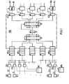
- FIG 1 a digital telecommunications system according to the invention is shown schematically in a scope necessary for understanding the invention.
- This telecommunication system has connecting lines connected to a switching node in a star structure that enables a central switching on request, these connecting lines in FIG. 1 on one side of a central telecommunication core TKK of the switching node as feeder lines Zl1 ... Zll; ...; Zln ... Zlz and on the other side as consumer lines Al1 ... All; ...; Aln ... Alz are shown.
- the connecting lines can be formed by subscriber lines of the existing symmetrical subscriber line network, which is at least suitable for bit rates up to approx.
- Both telecommunication devices EB1 ... EBn for burst traffic mediated on request are connected to the telecommunication core TKK via the connecting lines, and telecommunication devices ES1 ... ESz for channel-switched stream traffic, for example telephone, text and / or image communication terminals.
- access control units ZB1 ... ZSB1; ...; ZBn ... ZSBz regulate the access of the individual feeder lines Zl to the central telecommunications core TKK:
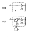
- the telecommunications devices can EB for access control units ZB, which are assigned to burst traffic and are configured in a manner known in principle for access control in local area networks (LAN); a corresponding block diagram is shown in FIG 2:
- the access control unit ZB effects the access of the feeder line Zl to a bus line B common to a plurality of feeder lines with the aid of an access switching device ZS which is controlled accordingly by a control device St which evaluates the signal states on the feeder line Zl and on the bus line B.
- the telecommunication devices ES are opened in the digital telecommunication system according to the invention outlined in FIG for channel-switched stream traffic associated access control units ZSB - assuming that these telecommunication devices ES do not deliver any message packets which also contain destination addresses and possibly service information - initially no access to the telecommunication core TKK.
- the telecommunication devices ES Rather, access control units ZSB assigned to channel-switched stream traffic initially, at the start of a connection, provide access for the respective connecting line Z1 to a switching processor VPI ...
- VPN which evaluates the service and destination information provided by the respective telecommunication device ES at the start of the connection in question and returns the target information converted into a form suitable for a transfer on request to the relevant access control unit ZSB, where the converted target information is stored; Only then does the access control unit ZSB then cause the relevant connecting line Z1 to access the central telecommunications core TKK, via which the connection is then switched according to the converted target information.
- the basic circuit diagram in FIG. 3 shows how the access control unit outlined in FIG. 2 can be supplemented:
- the connecting line Z1 is first of all for destination and possibly also service information about an input / output part of a switching processor VP connected so that it receives destination and possibly also service information arriving via a connecting line Zl in the course of establishing a connection from a telecommunication device for channel-switched stream traffic, in order then to convert it into a form suitable for the switching on request.
- An address memory AS of the access control unit ZSB is also connected to the input / output part of the switching processor VP, in which the evaluated target information is then stored. As is also indicated in FIG.
- the reversing device US can be controlled from the address memory AS, so that after inputting the converted target information into the address memory AS via the connecting line Z1 incoming, useful information representing digital signals to an input of in principle with a clock-controlled shift register circuit to be implemented packetization device PE, which is also connected on the input side to the output of the address memory AS.
- any further signaling information arriving via the connecting line Z1 can also continue to reach the switching processor VP or the address memory AS via the reversing device US;
- signaling information, in particular also target information, which has been worked out from the switching process by a switching processor or also by a central switching control unit can be entered into such an address memory without this being shown in FIG. 3.
- the packaging device PE forms, from the digital signals arriving via the connection line Z1, in each case, with the addition of the target information supplied by the address memory AS, suitable message packets for further transmission on request, which packets passes them on via their output line Z1 '.
- the message packets occurring on line Z1 ' can then be forwarded via a subsequent access switching device ZS controlled by a control device St to a bus line B common to a plurality of feeder lines in a manner corresponding to the processes explained above with reference to FIG. 2, without this being repeated here should be explained.
- the bus lines provided there each of which can be reached by a plurality of access control units ZB1, ... ZSB1; ...; ZBn ... ZSBz, form the input lines of waiting field memories each having a plurality of memory cells WFa, WFb, ... WFw.
- the access lines to the central telecommunications core TKK are regulated in such a way that that first of all the access lines provided individually at the telecommunications core, as well as the feeder lines Zl1 ... Zll; ...; Zln ... Zlz divided into groups access control units ZB1 ... ZSB1; ...; ZBn ...
- ZSBz only the access of their respective connection line to at least one waiting field memory WFa which is assigned to the respective group and has a plurality of memory cells; ...; regulate WFw.
- Digital signals transmitted on the feeder lines Zl1 ... Zll of a feeder line group in the direction of the central telecommunication core are combined with the associated access control units, in the example of the access control units ZB1 ... ZSB1, in each case with the associated destination address to form a packet, in the order in which they occur of the individual packets first entered into the respective waiting field memory, for example into the waiting field memory WFa.
- a group of up to 8 feeder lines can be connected to a waiting field (WFa) using a correspondingly fast access procedure in the example, which for this purpose with a bit throughput rate of 16 Mbit / s in the example is operated. Waiting times or losses can also be reduced if, as is also indicated in the drawing, the access control units ZB1 ... ZSBl one and the same group of access control units as well as the access of their connecting lines to the waiting field memory WFa assigned to this group Access of their connecting lines to another group of connecting lines or
- Control waiting area memory assigned to access control units in the example the waiting area memory WFb, with the same also correspondingly for the other groups of connecting lines Z1 and feeder control units ZB, ZSB.
- the waiting field memories WFa ... WFw are polled cyclically with the aid of a cyclically operated coupling switch ZK, one of the packets contained in the just queried waiting field memory WF preferably being transferred in parallel to a central packet memory cell ZZ.
- the central packet memory cell ZZ can be connected on the output side via an addressable controllable coupling switch AK to coupling memory cells KZa; ...; KZk, which are each assigned to a group of customer lines A11 ... All; ...; Aln ... Alz.
- the coupling switch AK is controlled by the destination address of the packet located in the packet memory cell ZZ, so that the packet in question, preferably again in parallel, in accordance with its destination address via the coupling switch AK straight into that coupling memory cell, for example, the coupling memory cell KZk, which is assigned to the customer line group Aln ... Alz containing the customer line designated by the destination address, for example the customer line Alz.
- the coupling memory cells KZa ... KZk are in turn on the output side via at least one further stage of address-controlled coupling devices WKa ... WKk with the individual customer lines A1 of the respective one Group of customer lines connectable.
- the respective coupling device for example the coupling device WKk, is controlled by the destination address of the packet under consideration, which in the example came into the coupling memory cell KZk, so that the packet in question finally, now again in series representation, to the by the destination address designated customer lines, in the example to the customer line Alz, is switched through.
- the useful signals contained in the through-connected message packets can again be converted into a bit stream corresponding to a stream traffic - taking into account a given time-division multiplex channel interleaving, for example by means of additional addresses of origin - which will not be considered here, however.
Landscapes
- Engineering & Computer Science (AREA)
- Computer Networks & Wireless Communication (AREA)
- Signal Processing (AREA)
- Data Exchanges In Wide-Area Networks (AREA)
- Mobile Radio Communication Systems (AREA)
- Small-Scale Networks (AREA)
Priority Applications (1)
| Application Number | Priority Date | Filing Date | Title |
|---|---|---|---|
| AT84110293T ATE34894T1 (de) | 1983-09-01 | 1984-08-29 | Digital-telekommunikationssystem mit sternstruktur seiner anschlussleitungen. |
Applications Claiming Priority (2)
| Application Number | Priority Date | Filing Date | Title |
|---|---|---|---|
| DE3331632 | 1983-09-01 | ||
| DE19833331632 DE3331632A1 (de) | 1983-09-01 | 1983-09-01 | Digital-telekommunikationssystem mit sternstruktur seiner anschlussleitungen |
Publications (3)
| Publication Number | Publication Date |
|---|---|
| EP0143202A2 true EP0143202A2 (fr) | 1985-06-05 |
| EP0143202A3 EP0143202A3 (en) | 1985-07-17 |
| EP0143202B1 EP0143202B1 (fr) | 1988-06-01 |
Family
ID=6208039
Family Applications (1)
| Application Number | Title | Priority Date | Filing Date |
|---|---|---|---|
| EP84110293A Expired EP0143202B1 (fr) | 1983-09-01 | 1984-08-29 | Système de télécommunication numérique avec des lignes d'abonnés structurées en étoile |
Country Status (3)
| Country | Link |
|---|---|
| EP (1) | EP0143202B1 (fr) |
| AT (1) | ATE34894T1 (fr) |
| DE (2) | DE3331632A1 (fr) |
Family Cites Families (3)
| Publication number | Priority date | Publication date | Assignee | Title |
|---|---|---|---|---|
| CH584488A5 (fr) * | 1975-05-05 | 1977-01-31 | Ibm | |
| FR2500704A1 (fr) * | 1981-02-20 | 1982-08-27 | Devault Michel | Commutateur temporel asynchrone pour reseau numerique a integration des services |
| FR2503497B1 (fr) * | 1981-04-03 | 1988-07-08 | Telephonie Ind Commerciale | Systeme temporel de telecommunications |
-
1983
- 1983-09-01 DE DE19833331632 patent/DE3331632A1/de not_active Withdrawn
-
1984
- 1984-08-29 DE DE8484110293T patent/DE3471860D1/de not_active Expired
- 1984-08-29 EP EP84110293A patent/EP0143202B1/fr not_active Expired
- 1984-08-29 AT AT84110293T patent/ATE34894T1/de not_active IP Right Cessation
Also Published As
| Publication number | Publication date |
|---|---|
| ATE34894T1 (de) | 1988-06-15 |
| DE3471860D1 (en) | 1988-07-07 |
| EP0143202B1 (fr) | 1988-06-01 |
| DE3331632A1 (de) | 1985-03-21 |
| EP0143202A3 (en) | 1985-07-17 |
Similar Documents
| Publication | Publication Date | Title |
|---|---|---|
| DE3904403C2 (fr) | ||
| DE3788605T2 (de) | Paketvermittlung. | |
| DE2559006C2 (de) | Nachrichtenübertragungsanlage, insbesondere Fernsprech- und Datenvermittlungssystem | |
| EP0363499B1 (fr) | Méthode et dispositif pour transmettre des signaux vocaux dans un réseau de communication à large bande | |
| DE3788911T2 (de) | Verteiltes Paketvermittlungssystem. | |
| EP0528087A1 (fr) | Procédé et agencement pour la communication des informations STM à travers des commutateurs ATM | |
| DE69031438T2 (de) | Kommunikationsprotokoll für statistische Datenmultiplexer in einer Weitbereichsnetzanordnung | |
| EP0365693B1 (fr) | Méthode et dispositif pour transmettre des signaux d'information dans un réseau de communication à large bande | |
| EP0528086A1 (fr) | Procédé et agencement pour la communication des informations STM à travers des commutateurs ATM | |
| DE3689894T2 (de) | Steuern von Multiport-Freiwahlgruppen in einem Vermittlungssystem mit verteilter Steuerung. | |
| DE3788314T2 (de) | Zeitstufengesteuerter Multiplexer. | |
| EP0110464B1 (fr) | Standard privé | |
| DE2211400C2 (de) | Zweistufiges Zeitmultiplex-Vermittlungssystem | |
| DE3808413C1 (fr) | ||
| DE4008729C2 (fr) | ||
| EP0173274B1 (fr) | Méthode et montage pour la réalisation et la maintenance d'une liaison à division temporelle à large bande | |
| EP0143203B1 (fr) | Système de télécommunication numérique avec des lignes d'abonnés structurées en étoile | |
| EP0143202B1 (fr) | Système de télécommunication numérique avec des lignes d'abonnés structurées en étoile | |
| DE3816747A1 (de) | Leistungsvermittelnde paket-vermittlungseinrichtung | |
| DE69209368T2 (de) | Übertragungskanäle mit veränderlicher Datenrate für digitale Netzwerke | |
| EP0343319B1 (fr) | Procédé de transmission d'informations numériques pour systèmes de commutation de communications | |
| DE3107671A1 (de) | Digitale fernmelde-durchschalteeinrichtung | |
| EP0984658B1 (fr) | Système de télécommunication avec commutateur et concentrateur de données pour l'accès vers Internet | |
| EP0797371B1 (fr) | Dispositif de commutation et procédé d'attribution d'intervalles de temps jour une connexion à voies multiples dans un dispositif de commutation | |
| EP0126413A2 (fr) | Système de télécommunication à la fois pour trafic en mode-circuit et pour trafic en mode-paquet |
Legal Events
| Date | Code | Title | Description |
|---|---|---|---|
| PUAI | Public reference made under article 153(3) epc to a published international application that has entered the european phase |
Free format text: ORIGINAL CODE: 0009012 |
|
| PUAL | Search report despatched |
Free format text: ORIGINAL CODE: 0009013 |
|
| AK | Designated contracting states |
Designated state(s): AT BE CH DE FR GB IT LI NL SE |
|
| AK | Designated contracting states |
Designated state(s): AT BE CH DE FR GB IT LI NL SE |
|
| 17P | Request for examination filed |
Effective date: 19851218 |
|
| 17Q | First examination report despatched |
Effective date: 19870410 |
|
| GRAA | (expected) grant |
Free format text: ORIGINAL CODE: 0009210 |
|
| AK | Designated contracting states |
Kind code of ref document: B1 Designated state(s): AT BE CH DE FR GB IT LI NL SE |
|
| REF | Corresponds to: |
Ref document number: 34894 Country of ref document: AT Date of ref document: 19880615 Kind code of ref document: T |
|
| GBT | Gb: translation of ep patent filed (gb section 77(6)(a)/1977) | ||
| REF | Corresponds to: |
Ref document number: 3471860 Country of ref document: DE Date of ref document: 19880707 |
|
| ET | Fr: translation filed | ||
| ITF | It: translation for a ep patent filed | ||
| PLBE | No opposition filed within time limit |
Free format text: ORIGINAL CODE: 0009261 |
|
| STAA | Information on the status of an ep patent application or granted ep patent |
Free format text: STATUS: NO OPPOSITION FILED WITHIN TIME LIMIT |
|
| 26N | No opposition filed | ||
| ITTA | It: last paid annual fee | ||
| PGFP | Annual fee paid to national office [announced via postgrant information from national office to epo] |
Ref country code: SE Payment date: 19920814 Year of fee payment: 9 Ref country code: BE Payment date: 19920814 Year of fee payment: 9 |
|
| PGFP | Annual fee paid to national office [announced via postgrant information from national office to epo] |
Ref country code: FR Payment date: 19920821 Year of fee payment: 9 |
|
| PGFP | Annual fee paid to national office [announced via postgrant information from national office to epo] |
Ref country code: NL Payment date: 19920831 Year of fee payment: 9 |
|
| PGFP | Annual fee paid to national office [announced via postgrant information from national office to epo] |
Ref country code: CH Payment date: 19921120 Year of fee payment: 9 |
|
| PGFP | Annual fee paid to national office [announced via postgrant information from national office to epo] |
Ref country code: GB Payment date: 19930714 Year of fee payment: 10 |
|
| PGFP | Annual fee paid to national office [announced via postgrant information from national office to epo] |
Ref country code: AT Payment date: 19930716 Year of fee payment: 10 |
|
| PG25 | Lapsed in a contracting state [announced via postgrant information from national office to epo] |
Ref country code: SE Effective date: 19930830 |
|
| PG25 | Lapsed in a contracting state [announced via postgrant information from national office to epo] |
Ref country code: LI Effective date: 19930831 Ref country code: CH Effective date: 19930831 Ref country code: BE Effective date: 19930831 |
|
| BERE | Be: lapsed |
Owner name: SIEMENS A.G. BERLIN UND MUNCHEN Effective date: 19930831 |
|
| PG25 | Lapsed in a contracting state [announced via postgrant information from national office to epo] |
Ref country code: NL Effective date: 19940301 |
|
| NLV4 | Nl: lapsed or anulled due to non-payment of the annual fee | ||
| PG25 | Lapsed in a contracting state [announced via postgrant information from national office to epo] |
Ref country code: FR Effective date: 19940429 |
|
| REG | Reference to a national code |
Ref country code: CH Ref legal event code: PL |
|
| REG | Reference to a national code |
Ref country code: FR Ref legal event code: ST |
|
| PG25 | Lapsed in a contracting state [announced via postgrant information from national office to epo] |
Ref country code: GB Effective date: 19940829 Ref country code: AT Effective date: 19940829 |
|
| PGFP | Annual fee paid to national office [announced via postgrant information from national office to epo] |
Ref country code: DE Payment date: 19941018 Year of fee payment: 11 |
|
| EUG | Se: european patent has lapsed |
Ref document number: 84110293.2 Effective date: 19940310 |
|
| GBPC | Gb: european patent ceased through non-payment of renewal fee |
Effective date: 19940829 |
|
| PG25 | Lapsed in a contracting state [announced via postgrant information from national office to epo] |
Ref country code: DE Effective date: 19960501 |