EP0143263B1 - Interrupteur à clé - Google Patents
Interrupteur à clé Download PDFInfo
- Publication number
- EP0143263B1 EP0143263B1 EP84111583A EP84111583A EP0143263B1 EP 0143263 B1 EP0143263 B1 EP 0143263B1 EP 84111583 A EP84111583 A EP 84111583A EP 84111583 A EP84111583 A EP 84111583A EP 0143263 B1 EP0143263 B1 EP 0143263B1
- Authority
- EP
- European Patent Office
- Prior art keywords
- housing
- key
- lock
- cylinder
- operated switch
- Prior art date
- Legal status (The legal status is an assumption and is not a legal conclusion. Google has not performed a legal analysis and makes no representation as to the accuracy of the status listed.)
- Expired
Links
- 238000007789 sealing Methods 0.000 claims description 15
- 230000015572 biosynthetic process Effects 0.000 claims description 12
- 238000009434 installation Methods 0.000 claims description 3
- 239000004033 plastic Substances 0.000 claims description 2
- 229920003023 plastic Polymers 0.000 claims description 2
- 238000010276 construction Methods 0.000 claims 1
- 239000000463 material Substances 0.000 claims 1
- 238000000034 method Methods 0.000 claims 1
- 239000012858 resilient material Substances 0.000 claims 1
- 238000004519 manufacturing process Methods 0.000 description 2
- 230000002411 adverse Effects 0.000 description 1
- 238000013475 authorization Methods 0.000 description 1
- 230000006735 deficit Effects 0.000 description 1
- 238000005516 engineering process Methods 0.000 description 1
- 238000000465 moulding Methods 0.000 description 1
Images

Classifications
-
- H—ELECTRICITY
- H01—ELECTRIC ELEMENTS
- H01H—ELECTRIC SWITCHES; RELAYS; SELECTORS; EMERGENCY PROTECTIVE DEVICES
- H01H27/00—Switches operated by a removable member, e.g. key, plug or plate; Switches operated by setting members according to a single predetermined combination out of several possible settings
- H01H27/06—Key inserted and then turned to effect operation of the switch
-
- H—ELECTRICITY
- H01—ELECTRIC ELEMENTS
- H01H—ELECTRIC SWITCHES; RELAYS; SELECTORS; EMERGENCY PROTECTIVE DEVICES
- H01H27/00—Switches operated by a removable member, e.g. key, plug or plate; Switches operated by setting members according to a single predetermined combination out of several possible settings
- H01H27/06—Key inserted and then turned to effect operation of the switch
- H01H2027/066—Key inserted and then turned to effect operation of the switch having anti-tamper provisions, e.g. avoiding the removal of the lock cylinder
Definitions
- the invention relates to a key switch with the features of the preamble of claim 1.
- a profile half-cylinder lock is releasably attached to the housing cover only from the inside, the lock bit engages behind an intermediate plate in rotary positions outside a certain rotary position, on which the switch is fixed.
- the housing cover can be removed with screws accessible from the outside. Only the further opening of the housing interior containing the switch is only possible if one assumes that the housing cover cannot be rotated with the lock in such a way that the screws with which the intermediate plate is fixed to the housing part comprising the housing base are not accessible . In any case, it is possible for an unauthorized person to loosen the housing cover without a key, so that adverse weather influences can take hold even when there is no further access to the housing interior. Otherwise, this known key switch consists of a large number of components, which requires a corresponding outlay in terms of production technology.
- the invention has for its object to provide a key switch of the type mentioned, in which an opening of the housing without twisting the lock bit in the particular rotational position is not possible and which is created with a minimum of components.
- the inventive design of the key switch ensures that the housing cannot be opened at all without authorization, so that the attempt to operate the key switch without a key also excludes weather influences which can lead to impairment or undesired switching function.
- the switch according to the invention is designed such that only two housing parts are required, which accommodate the lock and the switch, so that the manufacture of the switch according to the invention is correspondingly simple and cheap, as far as the required fastening parts are concerned.
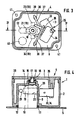
- the housing designated overall by 1, consists of a housing cover 2 and a housing part 4 comprising the housing base 3 (FIG. 3).
- the housing part 3 comprising the housing base 3 is not shown in FIG.
- a shield 5 is shown, which overlaps the surface of the housing cover 2 on all sides and is provided in the event that the switch housing 1 is installed in a so-called flush-mounted installation.
- the housing part 4 comprising the housing base 3 is practically limited to the base 3, that is to say the housing cover 2 encompasses the housing interior 6 almost completely.
- the housing part 4 comprising the housing base 3 in a pot-like manner, on the outer edge of which the practically flat housing cover 2 can then be placed. Any other parting line between the front surface 7 of the housing cover 2 and the housing base 3 can also be selected.
- the top view according to FIG. 1 on the front side 7 of the housing cover 2 shows the external view of the end 8, which is accessible from the outside, of the semi-cylinder lock 10 inserted into a molding 9 of the housing cover 2, a rubber sealing plate 11, which is shown in section in FIG. 2, being omitted.
- the rubber sealing plate 11 has a circular rim and surrounds with a recess the end 8 of the profile half-cylinder lock 10 which is accessible from the outside in close association and is fitted into a correspondingly circular recess 12 in such a way that when the blind shield 5 is screwed on and the pressure exerted thereby is exerted on the rubber sealing plate is pressed in sealing contact with the edge of the recess 12 and that of the accessible end 8 of the profile half-cylinder lock 10.
- the shape 9 of the housing cover 2 ( Figure 4) is adapted to the cross-sectional shape of the profile half-cylinder lock 10, so that the lock in the recess 9 is easy to insert and remove without being able to perform significant sideways movements.
- the depth of the recess 9 is also adapted to the lock 10. although this is not essential, however, this reduces the overall height of the switch to one Minimum reduced.
- a bore 15 is provided, through which a screw 16 is guided, which is screwed into a thread 17, which is located in a projection 18 of the housing base 3. The screw 16 is therefore only accessible when the semi-cylinder lock 10 is not in the formation 9.
- Figures 3 and 4 show that the beard 19 of the lock 10 in the course of its twisting movement in a plane perpendicular to the longitudinal axis of the lock cylinder passes through an opening 20 provided in the side wall of the formation 9 of the housing cover 2 when the lock 10 acts in a rotational position is, in which the lock bit is located outside the rotational position 21, in which it is in alignment within the elongated lock extension 22.
- the ball 27 is slightly larger in diameter than the bore 29, so that a positive engagement between the formation 9 and the lock 10 via the ball 27 and the bore 29 is ensured as long as the grub screw 28 is in a corresponding rotational position.
- the ball 27 can retract into the blind hole 30, so that the lock 10 can be removed from the recess 9 with the corresponding position of the lock bit 19.
- the blind hole 30 and thus the grub screw 28 is covered by the rubber sealing plate 11. Only after removing this sealing plate 11 is the grub screw 28 accessible. If an unauthorized person loosens this screw without having the key for the lock, he can release the lock from the lock, but the lock 10 cannot be removed from the recess 9 as long as the lock bit 19 has the upward edge of the Opening 20 engages in the side wall of the recess 9.
- the switch designated overall by 25, in the exemplary embodiment shown consists of two push-button elements 33 and 34, which are fixed to the housing base 3 via a projecting projection 35. Between the actuating members 36, only one of which is shown, and the lock bit 19, actuating webs 37 made of elastically deformable plastic are provided, which are held clamped to the housing base 3 or corresponding projections 38 thereon, and which hold the twisting movement of the lock bit 19 against the actuating members 36 forward the key switch elements 33, 34.
- the housing cover 2 engages via a sealing lip 39 on the other housing part 4 comprising the housing base 3, so that overall a tight housing formation can be ensured.
- the electrical feed line is sealingly guided through a cable bushing 40 formed in the housing base 3 or one of the side walls of the housing cover 2, as is known per se.
- Fastening holes 41 are provided on two diagonally opposite corner regions of the housing base 3, via which the housing can be screwed onto a wall or the like in a surface or flush-mounted installation.
- the edge provided with the sealing strip 39, which, as seen from the housing base 3, is designed to strive upwards, runs in this way. that the fastening openings 41 lie outside the housing, although the basic shape of the housing part 3 comprising the housing base 3 remains rectangular also in the bottom region.
Landscapes
- Switch Cases, Indication, And Locking (AREA)
- Push-Button Switches (AREA)
- Casings For Electric Apparatus (AREA)
Claims (10)
Priority Applications (1)
| Application Number | Priority Date | Filing Date | Title |
|---|---|---|---|
| AT84111583T ATE22195T1 (de) | 1983-10-03 | 1984-09-27 | Schluesselschalter. |
Applications Claiming Priority (3)
| Application Number | Priority Date | Filing Date | Title |
|---|---|---|---|
| DE8328372U DE8328372U1 (de) | 1983-10-03 | 1983-10-03 | Schlüsselschalter |
| DE3335867 | 1983-10-03 | ||
| DE19833335867 DE3335867A1 (de) | 1983-10-03 | 1983-10-03 | Schluesselschalter |
Publications (2)
| Publication Number | Publication Date |
|---|---|
| EP0143263A1 EP0143263A1 (fr) | 1985-06-05 |
| EP0143263B1 true EP0143263B1 (fr) | 1986-09-10 |
Family
ID=25814547
Family Applications (1)
| Application Number | Title | Priority Date | Filing Date |
|---|---|---|---|
| EP84111583A Expired EP0143263B1 (fr) | 1983-10-03 | 1984-09-27 | Interrupteur à clé |
Country Status (2)
| Country | Link |
|---|---|
| EP (1) | EP0143263B1 (fr) |
| DE (2) | DE8328372U1 (fr) |
Families Citing this family (5)
| Publication number | Priority date | Publication date | Assignee | Title |
|---|---|---|---|---|
| DE8710596U1 (de) * | 1987-08-03 | 1988-12-01 | DOM-Sicherheitstechnik GmbH & Co KG, 5040 Brühl | Zylinderbetätigbarer Schlüsselschalter |
| DE4218660C1 (de) * | 1992-06-05 | 1994-01-27 | Eduard Schindler | Profilzylinderschaltschloß |
| DE9403744U1 (de) * | 1994-03-05 | 1994-05-26 | Skultety, Ivan, 50767 Köln | Schlüsselschalter |
| DE19830139B4 (de) * | 1998-07-06 | 2017-01-19 | Geba Elektromechanische und elektronische Schaltgeräte Fabrik GmbH | Schlüsselschaltervorrichtung |
| DE10231725B4 (de) * | 2002-07-13 | 2009-04-02 | Abb Ag | Schlüsselschalter |
Family Cites Families (4)
| Publication number | Priority date | Publication date | Assignee | Title |
|---|---|---|---|---|
| DE1640578A1 (de) * | 1967-12-30 | 1970-12-17 | Industriebedarf Handelsgmbh | Schluesselbetaetigter Sicherheitsschalter |
| DE7206369U (fr) * | 1972-02-21 | 1972-05-25 | Baumgart F | |
| DE2437977C3 (de) * | 1974-08-07 | 1978-12-21 | Te Ka De Felten & Guilleaume Fernmeldeanlagen Gmbh, 8500 Nuernberg | Schlüsselschalter in kleiner Bauweise, insbesondere für ein Funkgerät |
| DE2856337A1 (de) * | 1978-12-27 | 1980-07-10 | Alltronik Gmbh | Schluesselschalter |
-
1983
- 1983-10-03 DE DE8328372U patent/DE8328372U1/de not_active Expired
- 1983-10-03 DE DE19833335867 patent/DE3335867A1/de not_active Ceased
-
1984
- 1984-09-27 EP EP84111583A patent/EP0143263B1/fr not_active Expired
Also Published As
| Publication number | Publication date |
|---|---|
| DE8328372U1 (de) | 1985-03-14 |
| DE3335867A1 (de) | 1985-04-18 |
| EP0143263A1 (fr) | 1985-06-05 |
Similar Documents
| Publication | Publication Date | Title |
|---|---|---|
| DE3812972C1 (fr) | ||
| EP0054225B1 (fr) | Serrure encastrée pour boîtes de commutation ou similaires | |
| DE4020581A1 (de) | Wasser- und staubdichter drucktastenschalter | |
| DE3833032A1 (de) | Anschlussdose fuer fernsprech-apparate und/oder fernsprech-zusatzgeraete | |
| EP0143263B1 (fr) | Interrupteur à clé | |
| DE19914568C2 (de) | Magnetbetätigbarer Melder mit Reed-Kontakt | |
| EP0735800B1 (fr) | Appareil pour alimenter une lampe électrique | |
| DE9105667U1 (de) | Erdungsmutter | |
| DE19802146A1 (de) | Vorrichtung zum Verriegeln einer Schranktür | |
| DE19815602A1 (de) | Befestigungssystem zum Befestigen einer Platte innerhalb eines Gehäuses | |
| EP1080515B1 (fr) | Systeme de fermeture a barres muni d'un dispositif de mise a la terre | |
| EP0270802A1 (fr) | Dispositif pour sceller et simultanément verrouiller mécaniquement un couvercle sur un appareil | |
| DE3738907C2 (fr) | ||
| DE2622961A1 (de) | Schloss mit mindestens einem beim einfuehren des schluessels ausweichenden schliessorgan und verfahren zur erstellung dieses schlosses | |
| DE3538757A1 (de) | Revisionsabdeckung | |
| DE4400828C2 (de) | Badezimmerschrank mit einem Kunststoffgehäuse | |
| EP0213296B1 (fr) | Agencement pour la mise en marche et l'arrêt d'un aspirateur | |
| DE9014420U1 (de) | Telekommunikationsanschlußdose | |
| DE3431358A1 (de) | Versenkbarer verschluss fuer schaltschranktueren | |
| DE19926240A1 (de) | Schutzvorrichtung | |
| DE2856337A1 (de) | Schluesselschalter | |
| DE2006083B2 (de) | Unterputzsteckdose | |
| DE19825242A1 (de) | Elektrisches Installationsgerät | |
| DE29615939U1 (de) | Treibstangenanschluß für ein Treibstangenschloß | |
| DE3021290A1 (de) | Verschlusseinrichtung |
Legal Events
| Date | Code | Title | Description |
|---|---|---|---|
| PUAI | Public reference made under article 153(3) epc to a published international application that has entered the european phase |
Free format text: ORIGINAL CODE: 0009012 |
|
| AK | Designated contracting states |
Designated state(s): AT BE CH DE FR GB IT LI LU NL SE |
|
| RBV | Designated contracting states (corrected) |
Designated state(s): AT BE CH DE FR GB LI NL |
|
| 17P | Request for examination filed |
Effective date: 19850605 |
|
| 17Q | First examination report despatched |
Effective date: 19860123 |
|
| GRAA | (expected) grant |
Free format text: ORIGINAL CODE: 0009210 |
|
| AK | Designated contracting states |
Kind code of ref document: B1 Designated state(s): AT BE CH DE FR GB LI NL |
|
| REF | Corresponds to: |
Ref document number: 22195 Country of ref document: AT Date of ref document: 19860915 Kind code of ref document: T |
|
| REF | Corresponds to: |
Ref document number: 3460707 Country of ref document: DE Date of ref document: 19861016 |
|
| ET | Fr: translation filed | ||
| PLBE | No opposition filed within time limit |
Free format text: ORIGINAL CODE: 0009261 |
|
| STAA | Information on the status of an ep patent application or granted ep patent |
Free format text: STATUS: NO OPPOSITION FILED WITHIN TIME LIMIT |
|
| 26N | No opposition filed | ||
| REG | Reference to a national code |
Ref country code: CH Ref legal event code: PFA Free format text: HOERMANN KG ANTRIEBS- U. STEUERUNGSTECHNIK TRANSFER- MARANTEC ANTRIEBS- UND STEUERUNGSTECHNIK GMBH & CO. KG. |
|
| REG | Reference to a national code |
Ref country code: GB Ref legal event code: IF02 |
|
| PGFP | Annual fee paid to national office [announced via postgrant information from national office to epo] |
Ref country code: GB Payment date: 20020829 Year of fee payment: 19 |
|
| PGFP | Annual fee paid to national office [announced via postgrant information from national office to epo] |
Ref country code: FR Payment date: 20020920 Year of fee payment: 19 |
|
| PGFP | Annual fee paid to national office [announced via postgrant information from national office to epo] |
Ref country code: BE Payment date: 20020923 Year of fee payment: 19 Ref country code: AT Payment date: 20020923 Year of fee payment: 19 |
|
| PGFP | Annual fee paid to national office [announced via postgrant information from national office to epo] |
Ref country code: NL Payment date: 20020926 Year of fee payment: 19 Ref country code: DE Payment date: 20020926 Year of fee payment: 19 |
|
| PGFP | Annual fee paid to national office [announced via postgrant information from national office to epo] |
Ref country code: CH Payment date: 20021001 Year of fee payment: 19 |
|
| PG25 | Lapsed in a contracting state [announced via postgrant information from national office to epo] |
Ref country code: GB Free format text: LAPSE BECAUSE OF NON-PAYMENT OF DUE FEES Effective date: 20030927 Ref country code: AT Free format text: LAPSE BECAUSE OF NON-PAYMENT OF DUE FEES Effective date: 20030927 |
|
| PG25 | Lapsed in a contracting state [announced via postgrant information from national office to epo] |
Ref country code: LI Free format text: LAPSE BECAUSE OF NON-PAYMENT OF DUE FEES Effective date: 20030930 Ref country code: CH Free format text: LAPSE BECAUSE OF NON-PAYMENT OF DUE FEES Effective date: 20030930 Ref country code: BE Free format text: LAPSE BECAUSE OF NON-PAYMENT OF DUE FEES Effective date: 20030930 |
|
| BERE | Be: lapsed |
Owner name: *HORMANN K.G. ANTRIEBS- UND STEUERUNGSTECHNIK Effective date: 20030930 |
|
| PG25 | Lapsed in a contracting state [announced via postgrant information from national office to epo] |
Ref country code: NL Free format text: LAPSE BECAUSE OF NON-PAYMENT OF DUE FEES Effective date: 20040401 Ref country code: DE Free format text: LAPSE BECAUSE OF NON-PAYMENT OF DUE FEES Effective date: 20040401 |
|
| REG | Reference to a national code |
Ref country code: CH Ref legal event code: PL |
|
| GBPC | Gb: european patent ceased through non-payment of renewal fee |
Effective date: 20030927 |
|
| PG25 | Lapsed in a contracting state [announced via postgrant information from national office to epo] |
Ref country code: FR Free format text: LAPSE BECAUSE OF NON-PAYMENT OF DUE FEES Effective date: 20040528 |
|
| NLV4 | Nl: lapsed or anulled due to non-payment of the annual fee |
Effective date: 20040401 |
|
| REG | Reference to a national code |
Ref country code: FR Ref legal event code: ST |