EP0143503A2 - Implantierbare, handbedienbare Abgabeeinrichtung für flüssige Medikamente - Google Patents
Implantierbare, handbedienbare Abgabeeinrichtung für flüssige Medikamente Download PDFInfo
- Publication number
- EP0143503A2 EP0143503A2 EP84201719A EP84201719A EP0143503A2 EP 0143503 A2 EP0143503 A2 EP 0143503A2 EP 84201719 A EP84201719 A EP 84201719A EP 84201719 A EP84201719 A EP 84201719A EP 0143503 A2 EP0143503 A2 EP 0143503A2
- Authority
- EP
- European Patent Office
- Prior art keywords
- propelling
- dispenser according
- body member
- fluid
- propelling means
- Prior art date
- Legal status (The legal status is an assumption and is not a legal conclusion. Google has not performed a legal analysis and makes no representation as to the accuracy of the status listed.)
- Granted
Links
- 239000003814 drug Substances 0.000 title claims abstract description 81
- 239000012530 fluid Substances 0.000 title claims abstract description 34
- 230000000903 blocking effect Effects 0.000 claims abstract description 68
- 239000007788 liquid Substances 0.000 claims description 31
- 238000007789 sealing Methods 0.000 claims description 17
- 238000004891 communication Methods 0.000 claims description 9
- 230000000994 depressogenic effect Effects 0.000 claims description 9
- 230000004913 activation Effects 0.000 claims description 3
- 238000011144 upstream manufacturing Methods 0.000 claims 5
- 230000000712 assembly Effects 0.000 abstract description 5
- 238000000429 assembly Methods 0.000 abstract description 5
- 229920002379 silicone rubber Polymers 0.000 description 6
- 239000004945 silicone rubber Substances 0.000 description 6
- 239000000463 material Substances 0.000 description 4
- 238000004513 sizing Methods 0.000 description 4
- 230000000881 depressing effect Effects 0.000 description 3
- 239000000560 biocompatible material Substances 0.000 description 2
- 238000010276 construction Methods 0.000 description 2
- 239000002872 contrast media Substances 0.000 description 2
- 238000006073 displacement reaction Methods 0.000 description 2
- 229920002492 poly(sulfone) Polymers 0.000 description 2
- 239000012858 resilient material Substances 0.000 description 2
- 230000004044 response Effects 0.000 description 2
- 239000000932 sedative agent Substances 0.000 description 2
- 239000000853 adhesive Substances 0.000 description 1
- 230000001070 adhesive effect Effects 0.000 description 1
- 230000008901 benefit Effects 0.000 description 1
- 230000015572 biosynthetic process Effects 0.000 description 1
- 201000010099 disease Diseases 0.000 description 1
- 208000037265 diseases, disorders, signs and symptoms Diseases 0.000 description 1
- 229940079593 drug Drugs 0.000 description 1
- 230000009977 dual effect Effects 0.000 description 1
- 230000000694 effects Effects 0.000 description 1
- 239000000835 fiber Substances 0.000 description 1
- 239000000945 filler Substances 0.000 description 1
- 238000007667 floating Methods 0.000 description 1
- 238000012423 maintenance Methods 0.000 description 1
- 230000007257 malfunction Effects 0.000 description 1
- 238000000034 method Methods 0.000 description 1
- 238000012986 modification Methods 0.000 description 1
- 230000004048 modification Effects 0.000 description 1
- 230000037361 pathway Effects 0.000 description 1
- 229920000728 polyester Polymers 0.000 description 1
- 229940125723 sedative agent Drugs 0.000 description 1
- 230000001624 sedative effect Effects 0.000 description 1
- 150000003457 sulfones Chemical class 0.000 description 1
Images

Classifications
-
- A—HUMAN NECESSITIES
- A61—MEDICAL OR VETERINARY SCIENCE; HYGIENE
- A61M—DEVICES FOR INTRODUCING MEDIA INTO, OR ONTO, THE BODY; DEVICES FOR TRANSDUCING BODY MEDIA OR FOR TAKING MEDIA FROM THE BODY; DEVICES FOR PRODUCING OR ENDING SLEEP OR STUPOR
- A61M5/00—Devices for bringing media into the body in a subcutaneous, intra-vascular or intramuscular way; Accessories therefor, e.g. filling or cleaning devices, arm-rests
- A61M5/14—Infusion devices, e.g. infusing by gravity; Blood infusion; Accessories therefor
- A61M5/142—Pressure infusion, e.g. using pumps
- A61M5/14244—Pressure infusion, e.g. using pumps adapted to be carried by the patient, e.g. portable on the body
- A61M5/14276—Pressure infusion, e.g. using pumps adapted to be carried by the patient, e.g. portable on the body specially adapted for implantation
- A61M5/1428—Pressure infusion, e.g. using pumps adapted to be carried by the patient, e.g. portable on the body specially adapted for implantation with manual pumping action
Definitions
- the invention generally relates to hand-operable dispensers for fluid medicaments, more particularly to dispensers that are implantable within the human body and that are constructed such that at least all of the parts thereof which, when implanted, contact internal portions of the body are made of a biocompatible material.
- Dispensers according to this invention include medicament propelling means and blocking means which cooperate with each other along a medicament flow channel within the device in order to provide controlled medicament flow therethrough to an outlet conduit which directs medicament to the desired location within the body.
- Sufferers from certain diseases may benefit from the dosed administration of a medicament such as a sedative directly to or in close proximity of the pain center.
- a medicament such as a sedative directly to or in close proximity of the pain center.
- pain centers may be located deep within the body, and the local administration of medication thereto typically involves a liquid medicament and requires means to transport the medicament to such an internal body location.
- administration involves a hypodermic syringe and needle and/or the services of a trained medical professional.
- Many patients will consider it advantageous if the dosage of such a liquid medicament could be safely and conveniently self-administered.
- any device or dispenser of medicament that has self-administration capabilities should also include means to safeguard against accidental or unintentional administration of the medicament.
- Another important consideration of self-administered medicament dispensers is that the medicament should be dispensed in quantities of known unit dosages.
- various dispensers that have been utilized or proposed heretofore for dispensing same are unsatisfactory since they include pivoting members, floating parts, or both that clog or stick after a period of use.
- the present invention provides dispensers for fluid medicaments that have structural features which permit the safe, controlled and convenient self-administration of unit dosages of fluid medicaments, which structural features avoid the use of components that pivot or float and that would tend to malfunction or easily plug up.
- Devices according to this invention are implantable, self-administered dispensers that include a body or casing having a flexible-walled reservoir assembled thereonto, a one-way filler or supply port assembly mounted on the casing and communicating with the reservoir, a connecting channel having a plurality of channel segments within the body, one such channel segment providing fluid passage communication between the reservoir and a one-way valve assembly. Positioned along a downstream segment of the connecting channel is a propelling assembly that advances fluid medicament through this channel section.
- a blocking assembly is also provided within a section of the connecting channel in order to permit, in cooperation with the propelling assembly, the controlled flow of fluid through the connecting channel and to an outlet from the device while, when dispensing is not desired, preventing fluid flow therethrough.
- a dosage of medicament is dispensed when the patient manipulates a portion of the propelling assembly that is accessible through the casing of the implanted device.
- the blocking assembly and propelling assembly cooperate to selectively open and close the connecting channel in order to permit, only when desired, the propelled passage of a dosage of medicament out of the device and through a delivery tube that opens at the location where the medicament is to be delivered.
- Another object of this invention is to provide an improved implantable medicament dispenser that permits the patient to safely and conveniently self-administer a medicament fluid, even one which is highly viscous.
- Another object of this invention is to provide a self-administration fluid medicament dispenser that dispenses a unit dosage of the medicament in response to only deliberate and knowing actions by the person administering the medicament.
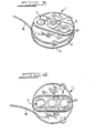
- the dispensing means illustrated in Figures 1, 3 and 4, generally designated by reference numeral 1 has a casing which typically includes an upstanding component 2 and a body component 3, both of which are made of a relatively rigid, biocompatible polymeric material.
- Polyethyl sulfone is an exemplary biocompatible material that is suitable in this regard.
- Upstanding component 2 and body component 3 are provided as integrally molded units or are secured together and/or to each other by appropriate means such as ultrasonic sealing or structures which provide fixed connections such as adhesives or screws.
- a reservoir 4 is partly defined by a yielding wall 5 that is secured to the body component 3 by suitble means such as the illustrated snap-on ring 6 which provides a tight-sealing assembly of the periphery of the yielding wall 5 to the body component 3.
- Reservoir 4 is further defined by the underside of the body component 3.
- Yielding wall 5 is structured and fabricated of a material such that it insures that the liquid contents of the reservoir substantially fill the reservoir 4 even as the liquid medicament confined thereby is dispensed out of the reservoir 4.
- yielding wall 5 is displaced toward the body component 3 in order to maintain close confinement of the medicament remaining within the reservoir 4 so that the medicament therewithin is maintained under a substantially constant pressure and so that air pockets are not developed therewithin.
- Yielding wall 5 is, for example, suitably made of a silicone rubber material that is reinforced with polyester fibers.
- a supply port assembly generally designated by reference numeral 7, provides a pathway through which.the liquid medicament can be inserted into the reservoir 4 from outside of the patient's body, typically by means of a hypodermic needle device.
- Supply port assembly 7 includes a generally mushroom-shaped shut-off valve, generally designated by reference numeral 11, a needle stop plate 9 of generally known construction, and a domed pad 10 that projects above the upstanding component 2 of the device 1 in order to assist in the accurate location thereof when the device is implanted within the patient.
- Supply port assembly 7 further includes a chamber 12 that is recessed within the domed pad 10.
- the needle stop plate 9 and an extending cap 8a of the mushroom-shaped shutoff valve 11 are both disposed within the chamber 12.
- Channels 13 and 14 are provided through the extending cap 8a of the mushroom-shaped shutoff valve 11, which channels 13 and 14 communicate the chamber 12 with an annular space 15 located between the extending cap 8a and an extending foot 8 of the shutoff valve 11.
- the space 15 is countersunk to form a disk-shaped space 16 which receives the extending foot 8.
- Mushroom-shaped shutoff valve 11 is sized and structured such that its extending foot 8, under at-rest conditions, is sealingly positioned within the disk-shaped space 16, so as to prevent passage of liquid across the shutoff valve 11, particularly between the chamber 12 and the reservoir 4.
- Reservoir 4 is filled by inserting the needle of a hypodermic syringe filled with medicament through the domed pad 10, thereby engaging the substantially rigid stop plate 9 (made, for example, of a polysulfone).
- the stop plate 9 pushes on the extending cap 8a of the shutoff valve 11 which, because it is made of a resilient material such as a silicone rubber, is deformed and pushed inwardly until the extending foot 8 is pushed away from its engagement with the disk-shaped space 16.
- the plunger of the hypodermic needle When the plunger of the hypodermic needle is depressed and the liquid medicament flows out of the needle, the liquid medicament flows, by way of a slit-shaped space adjacent to the side wall of the needle stop plate 9, into the chamber 12, through channels 13 and 14, through the spaces 15 and 16, and into the reservoir 4.
- the domed pad 10 After the hypodermic needle is withdrawn from the domed pad 10, the domed pad 10 seals itself automatically in accordance with well-known self-sealing port principles, and the needle stop plate 9 returns to its at-rest position, which permits the mushroom-shaped shutoff valve 11 likewise to return to its at-rest position and original shape in order to once again block the passage of liquid between the chamber 12 and the reservoir 4.
- a connecting channel 17 having a plurality of channel segments traverses a path that ultimately provides fluid-passing communication between the reservoir 4 and a delivery tube 18.
- delivery tube 18 is made of a material that incorporates a contrast medium, so that the guiding of the delivery tube 18 to the site of treatment can be monitored by well-known X-ray techniques. Silicone rubber tubes incorporating such a contrast medium are suitable in this regard.
- an initial channel segment thereof provides a passageway between the reservoir 4 and a one-way valve assembly, generally designated by reference numeral 19, which includes a diaphragm 20, typically made of a resilient material such as silicone rubber, which, when the device is at rest, is in sealing engagement with a collar 21.
- Diaphragm 20 includes an aperture 22 through which liquid medicament may pass when the diaphragm 20 is moved by appropriate liquid pressures out of full sealing engagement with the collar 21.
- Blocking assembly 23 includes a plunger assembly for selectively opening and closing the recessed housing 24 to a further channel segment of the connecting channel 17 which is downstream of the blocking assembly 23.
- the illustrated plunger assembly of the blocking assembly 23 includes a pushbutton 25 (for example made of a polysulfone), a resilient sealing sleeve 26 (for example made of a silicone rubber) and a resilient pad 27 (for example made of a silicone rubber) into which the top portion of the pushbutton 25 is imbedded.
- Resilient pad 27 is structured so that the plunger assembly is loaded or biased such that, when the device is at rest, a corner edge 28 of the sealing sleeve 26 engages a surface of the recessed chamber 24, thereby closing communication between the recessed chamber 24 and the segment of the connecting channel 17 which is present when the blocking assembly 23 is in its illustrated at-rest position.
- the top surface of the resilient pad 27 is countersunk with respect to the outside surface of the upstanding casing component 2.
- Another one-way valve assembly is interposed between the previously described segment of the connecting segment 17 and a further downstream segment thereof.
- Downstream of the further segment of the connecting channel 17 is another blocking assembly, generally designated by reference numeral 33, which blocking assembly 33 is similar to blocking assembly 23, except for one important difference.
- Blocking assembly 33 is biased or loaded, by the configuration and sizing of its resilient pad 37, in a generally downwardly oriented position at which the bottom or inside surface of its pushbutton 35 engages the body component 3 in order to preclude the formation of a channel segment therebetween.
- a recessed chamber 34 within the body component 3 receives the lower portion of the pushbutton 35 and its sealing sleeve 36.
- the blocking assembly 33 moves upwardly until a corner edge 38 of the sealing sleeve 36 closes the recessed chamber 34, at which time a segment of the connecting channel 17 is formed between the upper surface of the body component 3 and the inside bottom surface of resilient pad 37 and the head of pushbutton 35.
- a segment of the connecting channel 17 is formed between the upper surface of the body component 3 and the inside bottom surface of resilient pad 37 and the head of pushbutton 35.
- connecting segment when present, communicates with a terminal section of the connecting channel 17, which opens to another one-way valve assembly, generally designated by reference numeral 39.
- one-way valve assembly 39 communicates with the delivery tube 18.
- One-way valve assembly 39 includes a diaphragm 40 in sealing engagement with a collar 41 when the device is at rest.
- Diaphragm 40 includes an aperture 42.
- the medicament dispensing device is shown in its at-rest or quiescent state at which it is in a non-dispensing mode.
- Each of the one-way valve assemblies 19, 29 and 39 are closed, and the blocking assembly 23 functions as a plunger in its uppermost or outwardly extending position, while the blocking assembly 33 functions as a plunger in its lowermost or inwardly directed position at which the corner edge 38 thereof is spaced from the body component 3.
- the blocking assembly 23 When it is desired to dispense a unit dosage of fluid medicament into and through the delivery tube 18, with fluid filled within the connecting channel 17, the user first depresses the blocking assembly 23, which propels fluid medicament that will raise or outwardly extend the blocking assembly 33.
- Dispensing is carried out when the thus outwardly extended blocking assembly 33 is depressed to return to its inwardly directed at-rest orientation which is the orientation shown in Figure 1.
- the blocking assembly 33 functions as a means for propelling the fluid through the terminal section of the connecting channel 17 and through the delivery tube 18.
- a metered quantity of liquid medicament is forced from the recessed housing or chamber 24 by movement of the pushbutton 25 and its sealing sleeve 26 into the recessed chamber 24, which displaces medicament generally upwardly through the blocking assembly 23 and to the next downstream segment of the connecting channel 17 toward the one-way valve assembly 29.
- This downstream displacement of fluid and simultaneous exertion of pressure on the diaphragm 20 of the one-way valve assembly 19 in order to maintain same in a closed state is facilitated by providing a spacing between bottom surface 46 of the blocking assembly 23, which is achieved in part by appropriately sizing the length of stem 43 of the pushbutton 25.
- This downstreamwardly directed pressure is imparted to liquid medicament already in the downstream section of connecting channel 17, which in turn exerts pressure on the diaphragm 30 of the one-way valve assembly 29, this in turn causing a lifting of the diaphragm 30 off of its collar 31, whereby the liquid medicament within this downstream section of the connecting channel 17 flows through aperture 32, then through the further downstream segment of the connecting channel 17, and into the recessed chamber 34 of the blocking assembly 33.
- the liquid medicament flowing through aperture 32 exerts a hydraulic force on the bottom surface 56 of the blocking assembly 33, which in turn raises the blocking assembly 33.
- This activity is assisted by providing spacing between the bottom surface 56 of the blocking assembly 33 and the opposing wall of the recessed chamber 34, which is accomplished by appropriately sizing stem 53 of the pushbutton 35.
- Blocking assembly 33 is thereby displaced upwardly or outwardly through a distance that is substantially equal to that through which the blocking assembly 23 is displaced inwardly when pressed by the user, such being achieved by providing generally equal volumeric respective sizings of the blocking assembly 23 and of the blocking assembly 33, their respective recessed chambers 24 and 34, so that the entire incremental volume of liquid medicament that is displaced from chamber 24 by depressing the blocking assembly 23 is received in the recessed chamber 34, at which time the recessed chamber 34 is sealed when the corner edge 38 engages the upper or outwardly directed surface of the recessed chamber 34.
- the outward or upward displacement of fluid medicament through the blocking assembly 33 could result in opening of the one-way valve assembly 39, which would permit a somewhat uncontrolled and non-incremental volume of liquid medicament to flow through the aperture 42 and into the delivery tube 18.
- this undesirable result should cease when the corner edge 38 seals off the recessed chamber 34, this possibility is preferably prevented by designing the one-way valve assembly 39 such that the pressure that is required to lift the diaphragm 40 off of its collar 41 is greater than the pressure required to displace the blocking assembly 33 outwardly or upwardly.
- this pressure required to open the one-way valve assembly 39 is less than that which is developed when the blocking assembly 33 is depressed.
- the hydraulic pressure generated by depressing the blocking assembly 33 is of such a high value that it lifts the diaphragm 40 off of its collar 41 to permit an incremental unitary dosage amount of liquid medicament to flow through the aperture 42, into the delivery tube 18 and to the site where the fluid medicament is to be administered.
- medicament flows from the reservoir 4 and through the aperture 22 of the one-way valve assembly 19, this flow being assisted by the collapsibility and flexibility of the yielding wall 5 such that the volume of the reservoir 4 is reduced as the yielding wall 5 collapses when the medicament passes through the one-way valve assembly 19 while the device is implanted and in contact with the patient.
- this device la includes only a single blocking assembly 23 which performs a dual function of providing blocking attributes while also functioning as means for propelling liquid medicament through the delivery tube 18, when such delivery is desired.
- Device la also includes a domed pad 10a projecting above upstanding component 2a providing a relatively simple construction for filling the reservoir 4 by passing a hypodermic needle therethrough.
- the one-way valve assembly 19 and a further one-way valve assembly 69 which does not have an aperture through its diaphragm, valve assemblies 19 and 69 being within body component 3a.
- the at-rest or quiescent state of device la is illustrated in Figure 2, this being the position of all components of the device la between the times at which. medicament dispensing is desired. More particularly, the blocking assembly 23 is in its upward or outwardly extending position at which the corner edge 28 of the sealing sleeve 26 sealingly engages the outwardly extending wall of the recessed chamber 24. When it is desired to supply a dose of medicament through the delivery tube 18, pressure is exerted on the pushbutton 25 through the resilient pad 27 of the blocking assembly 23 in order to depress same and remove the sealing engagement between the corner edge 28 and the recessed chamber 24.
- a channel 77 is provided for liquid pressure communication between the reservoir 4 and the diaphragm 70 of the one-way valve assembly 69.
- Aperture free diaphragm 70 is structured and positioned so that liquid medicament cannot flow therethrough from the channel 77.
- An increase in pressure caused by an increase in pressure on the outside surface of the reservoir 4 will enhance the seating of the diaphragm 70 onto its collar 71 in order to ensure that, if such outside pressure is increased onto the implanted reservoir 4, such increase will not cause medicament to be dispensed through the delivery tube 18.
Landscapes
- Health & Medical Sciences (AREA)
- Vascular Medicine (AREA)
- Engineering & Computer Science (AREA)
- Anesthesiology (AREA)
- Biomedical Technology (AREA)
- Heart & Thoracic Surgery (AREA)
- Hematology (AREA)
- Life Sciences & Earth Sciences (AREA)
- Animal Behavior & Ethology (AREA)
- General Health & Medical Sciences (AREA)
- Public Health (AREA)
- Veterinary Medicine (AREA)
- Infusion, Injection, And Reservoir Apparatuses (AREA)
Applications Claiming Priority (4)
| Application Number | Priority Date | Filing Date | Title |
|---|---|---|---|
| NL8304030 | 1983-11-23 | ||
| NL8304030 | 1983-11-23 | ||
| NL8400489 | 1984-02-15 | ||
| NL8400489A NL8400489A (nl) | 1983-11-23 | 1984-02-15 | Handbedienbare, in het lichaam implanteerbare doseerinrichting voor een stroombaar medikament. |
Publications (3)
| Publication Number | Publication Date |
|---|---|
| EP0143503A2 true EP0143503A2 (de) | 1985-06-05 |
| EP0143503A3 EP0143503A3 (en) | 1985-07-10 |
| EP0143503B1 EP0143503B1 (de) | 1989-02-01 |
Family
ID=26645906
Family Applications (1)
| Application Number | Title | Priority Date | Filing Date |
|---|---|---|---|
| EP19840201719 Expired EP0143503B1 (de) | 1983-11-23 | 1984-11-23 | Implantierbare, handbedienbare Abgabeeinrichtung für flüssige Medikamente |
Country Status (4)
| Country | Link |
|---|---|
| EP (1) | EP0143503B1 (de) |
| CA (1) | CA1243913A (de) |
| DE (1) | DE3476521D1 (de) |
| NL (1) | NL8400489A (de) |
Cited By (9)
| Publication number | Priority date | Publication date | Assignee | Title |
|---|---|---|---|---|
| EP0174757A1 (de) * | 1984-09-04 | 1986-03-19 | BAXTER INTERNATIONAL INC. (a Delaware corporation) | Implantierbare Vorrichtung für die Zuführung von Arzneimitteln nach Bedarf |
| EP0202696A1 (de) * | 1985-05-21 | 1986-11-26 | Applied Precision Limited | Handbetätigbare implantierbare Dosiervorrichtung für therapeutische Stoffe |
| FR2588757A1 (fr) * | 1985-10-21 | 1987-04-24 | Perouse Sa Laboratoires | Dispositif place sous la peau pour delivrer une substance medicamenteuse |
| WO1987006473A1 (fr) * | 1986-04-24 | 1987-11-05 | Centre National De La Recherche Scientifique (Cnrs | Dispositif implantable rechargeable pour auto-injection dosee et repetee de medicament |
| GB2192135A (en) * | 1986-06-26 | 1988-01-06 | Bristol Myers Co | Infusion erectile system |
| EP0231371A4 (de) * | 1985-08-06 | 1989-06-14 | Baxter Travenol Lab | Vom patienten kontrollierte verabreichung von heilmitteln. |
| EP0322978A1 (de) * | 1987-12-22 | 1989-07-05 | Cordis Europa N.V. | Implantierbares Stromüberwachungssystem mit Tonsignalen |
| EP0342947A3 (de) * | 1988-05-18 | 1990-06-13 | BAXTER INTERNATIONAL INC. (a Delaware corporation) | Implantierbare, vom Patienten aktivierte Vorrichtung zum Fördern von Flüssigkeiten mit einem Zugang für eine Bolusinjection |
| EP0701831A1 (de) * | 1994-09-16 | 1996-03-20 | Fresenius AG | Implantierbare Infusionspumpe |
Family Cites Families (5)
| Publication number | Priority date | Publication date | Assignee | Title |
|---|---|---|---|---|
| US3827439A (en) * | 1972-10-30 | 1974-08-06 | Heyer Schulte Corp | Plug valve for physiological shunt systems |
| US4013074A (en) * | 1974-06-21 | 1977-03-22 | Siposs George G | Implantable medication-dispensing device |
| US4152098A (en) * | 1977-01-03 | 1979-05-01 | Clark Ivan P | Micropump |
| US4221219A (en) * | 1978-07-31 | 1980-09-09 | Metal Bellows Corporation | Implantable infusion apparatus and method |
| US4364395A (en) * | 1981-06-30 | 1982-12-21 | American Heyer-Schulte Corporation | Low profile shunt system |
-
1984
- 1984-02-15 NL NL8400489A patent/NL8400489A/nl not_active Application Discontinuation
- 1984-11-16 CA CA000468064A patent/CA1243913A/en not_active Expired
- 1984-11-23 EP EP19840201719 patent/EP0143503B1/de not_active Expired
- 1984-11-23 DE DE8484201719T patent/DE3476521D1/de not_active Expired
Cited By (14)
| Publication number | Priority date | Publication date | Assignee | Title |
|---|---|---|---|---|
| EP0174757A1 (de) * | 1984-09-04 | 1986-03-19 | BAXTER INTERNATIONAL INC. (a Delaware corporation) | Implantierbare Vorrichtung für die Zuführung von Arzneimitteln nach Bedarf |
| US4634427A (en) * | 1984-09-04 | 1987-01-06 | American Hospital Supply Company | Implantable demand medication delivery assembly |
| EP0202696A1 (de) * | 1985-05-21 | 1986-11-26 | Applied Precision Limited | Handbetätigbare implantierbare Dosiervorrichtung für therapeutische Stoffe |
| FR2582222A1 (fr) * | 1985-05-21 | 1986-11-28 | Applied Precision Ltd | Dispositif implantable a action manuelle pour la distribution sequentielle de doses d'une substance, notamment therapeutique |
| EP0231371A4 (de) * | 1985-08-06 | 1989-06-14 | Baxter Travenol Lab | Vom patienten kontrollierte verabreichung von heilmitteln. |
| FR2588757A1 (fr) * | 1985-10-21 | 1987-04-24 | Perouse Sa Laboratoires | Dispositif place sous la peau pour delivrer une substance medicamenteuse |
| FR2599260A1 (fr) * | 1986-04-24 | 1987-12-04 | Centre Nat Rech Scient | Dispositif implantable rechargeable pour auto-injection dosee et repetee de medicament. |
| WO1987006473A1 (fr) * | 1986-04-24 | 1987-11-05 | Centre National De La Recherche Scientifique (Cnrs | Dispositif implantable rechargeable pour auto-injection dosee et repetee de medicament |
| US4857059A (en) * | 1986-04-24 | 1989-08-15 | Centre National De La Recherche Scientifique | Rechargeable implantable device for dosed and repeated self-injection of medicament |
| GB2192135A (en) * | 1986-06-26 | 1988-01-06 | Bristol Myers Co | Infusion erectile system |
| GB2192135B (en) * | 1986-06-26 | 1990-10-24 | Bristol Myers Co | Infusion erectile system |
| EP0322978A1 (de) * | 1987-12-22 | 1989-07-05 | Cordis Europa N.V. | Implantierbares Stromüberwachungssystem mit Tonsignalen |
| EP0342947A3 (de) * | 1988-05-18 | 1990-06-13 | BAXTER INTERNATIONAL INC. (a Delaware corporation) | Implantierbare, vom Patienten aktivierte Vorrichtung zum Fördern von Flüssigkeiten mit einem Zugang für eine Bolusinjection |
| EP0701831A1 (de) * | 1994-09-16 | 1996-03-20 | Fresenius AG | Implantierbare Infusionspumpe |
Also Published As
| Publication number | Publication date |
|---|---|
| DE3476521D1 (en) | 1989-03-09 |
| NL8400489A (nl) | 1985-06-17 |
| CA1243913A (en) | 1988-11-01 |
| EP0143503A3 (en) | 1985-07-10 |
| EP0143503B1 (de) | 1989-02-01 |
Similar Documents
| Publication | Publication Date | Title |
|---|---|---|
| US4668231A (en) | Implantable hand-operable dispensers for fluid medicaments | |
| US4548607A (en) | Implantable manually actuated medication dispensing system | |
| JP4156801B2 (ja) | 患者制御薬品投与装置 | |
| US7335186B2 (en) | Patient controlled drug delivery device | |
| US4013074A (en) | Implantable medication-dispensing device | |
| US4544371A (en) | Implantable metered dose drug delivery system | |
| US6605060B1 (en) | Patient controlled drug delivery device | |
| US4634427A (en) | Implantable demand medication delivery assembly | |
| US5053031A (en) | Pump infusion system | |
| EP0900099B1 (de) | Von patienten kontrollierbare durchflussregulierung für ein medikamentenabgabesystem | |
| EP0190477B1 (de) | Am Körper befestigtes Pumpengehäuse, sowie Pumpeneinrichtung mit einem solchen Gehäuse | |
| US7632247B2 (en) | Disposable infusion device with air trapping collapsible reservoir | |
| CN101516350A (zh) | 具有自动解锁机构的一次性输注装置 | |
| JPH03505538A (ja) | 連続/ボウラス注入装置 | |
| RU2238111C2 (ru) | Имплантируемая система для дозируемой инфузии | |
| JPH09285539A (ja) | 薬液自己注入用具 | |
| EP0143503A2 (de) | Implantierbare, handbedienbare Abgabeeinrichtung für flüssige Medikamente | |
| AU707645B2 (en) | Fluid administration apparatus | |
| CA1333144C (en) | Implantable drug delivery system | |
| JPH08308925A (ja) | 薬液自己注入用具 | |
| JPS60198161A (ja) | 皮下挿入可能な液体薬品用デイスペンサ− | |
| JPH024377A (ja) | 皮下に注入可能なモニタ装置 | |
| AU710177B2 (en) | Patient controlled drug delivery device | |
| WO2005089836A2 (en) | Apparatus and method for dispensing a liquid | |
| GB2307953A (en) | Fluid administration apparatus |
Legal Events
| Date | Code | Title | Description |
|---|---|---|---|
| PUAI | Public reference made under article 153(3) epc to a published international application that has entered the european phase |
Free format text: ORIGINAL CODE: 0009012 |
|
| PUAL | Search report despatched |
Free format text: ORIGINAL CODE: 0009013 |
|
| AK | Designated contracting states |
Designated state(s): DE FR GB IT NL SE |
|
| AK | Designated contracting states |
Designated state(s): DE FR GB IT NL SE |
|
| 17P | Request for examination filed |
Effective date: 19851128 |
|
| 17Q | First examination report despatched |
Effective date: 19861024 |
|
| ITF | It: translation for a ep patent filed | ||
| GRAA | (expected) grant |
Free format text: ORIGINAL CODE: 0009210 |
|
| AK | Designated contracting states |
Kind code of ref document: B1 Designated state(s): DE FR GB IT NL SE |
|
| PG25 | Lapsed in a contracting state [announced via postgrant information from national office to epo] |
Ref country code: SE Effective date: 19890201 |
|
| REF | Corresponds to: |
Ref document number: 3476521 Country of ref document: DE Date of ref document: 19890309 |
|
| ET | Fr: translation filed | ||
| PLBE | No opposition filed within time limit |
Free format text: ORIGINAL CODE: 0009261 |
|
| STAA | Information on the status of an ep patent application or granted ep patent |
Free format text: STATUS: NO OPPOSITION FILED WITHIN TIME LIMIT |
|
| 26N | No opposition filed | ||
| ITTA | It: last paid annual fee | ||
| PGFP | Annual fee paid to national office [announced via postgrant information from national office to epo] |
Ref country code: NL Payment date: 19960924 Year of fee payment: 13 |
|
| PGFP | Annual fee paid to national office [announced via postgrant information from national office to epo] |
Ref country code: GB Payment date: 19961009 Year of fee payment: 13 |
|
| PG25 | Lapsed in a contracting state [announced via postgrant information from national office to epo] |
Ref country code: GB Free format text: LAPSE BECAUSE OF NON-PAYMENT OF DUE FEES Effective date: 19971123 |
|
| PG25 | Lapsed in a contracting state [announced via postgrant information from national office to epo] |
Ref country code: NL Free format text: LAPSE BECAUSE OF NON-PAYMENT OF DUE FEES Effective date: 19980601 |
|
| GBPC | Gb: european patent ceased through non-payment of renewal fee |
Effective date: 19971123 |
|
| NLV4 | Nl: lapsed or anulled due to non-payment of the annual fee |
Effective date: 19980601 |
|
| REG | Reference to a national code |
Ref country code: FR Ref legal event code: TP |
|
| PGFP | Annual fee paid to national office [announced via postgrant information from national office to epo] |
Ref country code: DE Payment date: 20011102 Year of fee payment: 18 |
|
| PGFP | Annual fee paid to national office [announced via postgrant information from national office to epo] |
Ref country code: FR Payment date: 20011128 Year of fee payment: 18 |
|
| PG25 | Lapsed in a contracting state [announced via postgrant information from national office to epo] |
Ref country code: DE Free format text: LAPSE BECAUSE OF NON-PAYMENT OF DUE FEES Effective date: 20030603 |
|
| PG25 | Lapsed in a contracting state [announced via postgrant information from national office to epo] |
Ref country code: FR Free format text: LAPSE BECAUSE OF NON-PAYMENT OF DUE FEES Effective date: 20030731 |
|
| REG | Reference to a national code |
Ref country code: FR Ref legal event code: ST |