EP0143717A1 - Gerät und Verfahren zur raschen Messung der Herzfrequenz - Google Patents
Gerät und Verfahren zur raschen Messung der Herzfrequenz Download PDFInfo
- Publication number
- EP0143717A1 EP0143717A1 EP84402412A EP84402412A EP0143717A1 EP 0143717 A1 EP0143717 A1 EP 0143717A1 EP 84402412 A EP84402412 A EP 84402412A EP 84402412 A EP84402412 A EP 84402412A EP 0143717 A1 EP0143717 A1 EP 0143717A1
- Authority
- EP
- European Patent Office
- Prior art keywords
- dynamometer
- heart rate
- maxima
- pulse
- created
- Prior art date
- Legal status (The legal status is an assumption and is not a legal conclusion. Google has not performed a legal analysis and makes no representation as to the accuracy of the status listed.)
- Withdrawn
Links
- 238000000034 method Methods 0.000 title claims description 6
- 230000000747 cardiac effect Effects 0.000 title description 3
- 210000002321 radial artery Anatomy 0.000 claims abstract description 10
- 230000035488 systolic blood pressure Effects 0.000 claims abstract description 8
- 230000017531 blood circulation Effects 0.000 claims abstract description 6
- 238000001514 detection method Methods 0.000 claims description 6
- 230000000541 pulsatile effect Effects 0.000 description 4
- 230000035487 diastolic blood pressure Effects 0.000 description 3
- 230000004872 arterial blood pressure Effects 0.000 description 2
- 238000010586 diagram Methods 0.000 description 2
- 238000005259 measurement Methods 0.000 description 2
- 230000010349 pulsation Effects 0.000 description 2
- 206010003119 arrhythmia Diseases 0.000 description 1
- 230000006793 arrhythmia Effects 0.000 description 1
- 210000001367 artery Anatomy 0.000 description 1
- 230000036772 blood pressure Effects 0.000 description 1
- 230000008602 contraction Effects 0.000 description 1
- 230000004907 flux Effects 0.000 description 1
- 239000012528 membrane Substances 0.000 description 1
- 238000012986 modification Methods 0.000 description 1
- 230000004048 modification Effects 0.000 description 1
- 229920001296 polysiloxane Polymers 0.000 description 1
- 239000004065 semiconductor Substances 0.000 description 1
- 210000000707 wrist Anatomy 0.000 description 1
Images

Classifications
-
- A—HUMAN NECESSITIES
- A61—MEDICAL OR VETERINARY SCIENCE; HYGIENE
- A61B—DIAGNOSIS; SURGERY; IDENTIFICATION
- A61B5/00—Measuring for diagnostic purposes; Identification of persons
- A61B5/02—Detecting, measuring or recording for evaluating the cardiovascular system, e.g. pulse, heart rate, blood pressure or blood flow
- A61B5/024—Measuring pulse rate or heart rate
Definitions
- the present invention relates to an apparatus and method for measuring the heart rate making it possible to display in 2 or 3 seconds the number of contractions effected by the heart in one minute.
- the classic procedure for measuring the heart rate consists of grasping the wrist of a patient with one hand, identifying by touch the pulsating wave of the blood flow from the radial artery, counting zero by taking a reference point on the dial of an analog watch or by mentally noting the value displayed by a watch with digital display at the time of a maximum of the pulsating wave, to count one at the time of a second maximum of the pulsating wave, to count two at moment of a third maximum of the pulsating wave, and so on until a certain time, generally one minute, has elapsed.
- a first disadvantage of this method is that it takes at least a minute to know with relatively good accuracy the heart rate of a patient, and that it is necessary that during this minute the practitioner has not been distracted in any way because it would have made him forget either his reference in the passage of time or the account of the pulsations since the beginning of his observation.
- a second drawback of this method results from the fact that very often the practitioner, generally pressed for time, only counts pulsatile wave passages for fifteen seconds only, then multiplies by four the number of pulses identified since the start of his observation. This results in uncertainty about the determination of the heart rate of at least one pulse per fifteen seconds, that is to say at least four pulses per minute. It often results, if in addition the practitioner counts one instead of zero at the time of the first identified pulse, an uncertainty of eight pulses per minute.
- the object of the invention is essentially to eliminate these drawbacks as far as possible and to allow everyone to measure on themselves as easily as on someone else the number of heartbeats per minute with reliability. hitherto reserved for experienced specialists operating in good conditions of tranquility, and this in an extremely short time of two or three seconds.
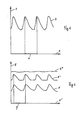
- FIG. 1 represents the evolution, as a function of the current time along axis 1, of an example of four arterial pressure cycles 3 carried along axis 2.
- the segment 4 separating two maxima represents the magnitude T of a period of the heart cycle.
- the maxima correspond to the systolic pressure of the blood flow, the minima to its diastolic pressure.
- FIG. 2 represents the evolution, as a function of the current time along the 1 axis, of an example of the voltages (expressed in volts) carried along the 5 axis supplied by the dynamometer used to detect the pulsatile wave of the arterial pressure.
- the tension 6 is obtained for a support force lower than that created by the diastolic pressure.
- the tension 6 ′ is obtained for a support force greater than that created by the diastolic pressure but less than that created by the systolic pressure.
- the tension 6 is obtained for a support force higher than that created by the systolic pressure. This practically constant tension does not make it possible to detect the maxima of the pulsatile wave and that is why it is necessary that the support force is less than that created by systolic pressure.
- segment 7 separating two maxima of the voltages 6 or 6 ' is equal to the segment 4 of FIG. 1, that is to say the magnitude T of a period of the cardiac cycle.
- FIG. 3 represents a side view of a preferred embodiment of the apparatus according to the invention which has the shape of a parallelepiped 8 with rounded edges which can for example be about 8 cm long and a section of 8 mm by 12 mm.
- the end 9 is slightly rounded and has a button 10 of about 5 mm in diameter rigidly connected to the membrane of the dynamometer.
- This is preferably made of conductive silicone and forms, with an internal insulated electrode, a variable capacitance modifying the frequency of an oscillator at the same rate as the pulsatile wave traversing the artery.
- the other end 11 is constituted by a display of three numeric characters.
- the body 12 of the device contains one or more electric batteries and the electronics necessary for the operation. This is permanently on as soon as the battery or batteries are placed in their housing.
- a clip 13 allows the attachment of the device in the pocket of a jacket or a blouse. like a pen.
- Figure 4 shows the display 11 seen from the front.
- the display 000 shown here is the one it provides before the device is pressed on the radial artery.
- FIG. 5 represents the device seen from below showing the end 9 containing the dynamometer and its button 10.
- FIG. 6 shows an example, in the form of a block diagram, of the general structure of a preferred embodiment of the apparatus of the invention and of the sequence of operations carried out on the voltage V supplied by the dynamometer in the 'hypothesis where the latter gives a continuous analog voltage, under the control of the clock H, before reaching the display 11.
- the voltage V is sampled and digitized.
- Block 15 searches for the maxima of V.
- Block 16 accumulates the increments of the clock H under the control of the maxima identified by block 15. It therefore provides the period T which, thanks to block 17, is inverted and multiplied by 60 to give the heart rate XXX which is sent to the control unit 18 of the display 11.
- the dynamometer signal is automatically analyzed i.e. that there is successively detection of a first maximum, triggering of the internal chronometer of the apparatus, detection of a second maximum, stop of the chronometer which then gives the value of the period T, calculation of 1 / T and its multiplicatior par 60, and display of this result which is the number of pulses per minute or heart rate.
- the measurement time is a maximum of two seconds. This duration can reach three seconds for a pulse of between 60 and 40 beats per minute.
- the display indicates a new heart rate value which is obviously identical to the previous one if the pulse is stable but which is different in the event of arrhythmia.
- the dynamometer used will preferably provide digital information and that this will advantageously be processed by semiconductor circuits of the microprocessor type of current use today.
Landscapes
- Health & Medical Sciences (AREA)
- Life Sciences & Earth Sciences (AREA)
- Cardiology (AREA)
- Biomedical Technology (AREA)
- Medical Informatics (AREA)
- Biophysics (AREA)
- Pathology (AREA)
- Engineering & Computer Science (AREA)
- Physiology (AREA)
- Heart & Thoracic Surgery (AREA)
- Physics & Mathematics (AREA)
- Molecular Biology (AREA)
- Surgery (AREA)
- Animal Behavior & Ethology (AREA)
- General Health & Medical Sciences (AREA)
- Public Health (AREA)
- Veterinary Medicine (AREA)
- Measuring Pulse, Heart Rate, Blood Pressure Or Blood Flow (AREA)
Applications Claiming Priority (2)
| Application Number | Priority Date | Filing Date | Title |
|---|---|---|---|
| FR8318856 | 1983-11-25 | ||
| FR8318856A FR2555431B1 (fr) | 1983-11-25 | 1983-11-25 | Appareil et procede pour mesurer tres rapidement le rythme cardiaque |
Publications (1)
| Publication Number | Publication Date |
|---|---|
| EP0143717A1 true EP0143717A1 (de) | 1985-06-05 |
Family
ID=9294548
Family Applications (1)
| Application Number | Title | Priority Date | Filing Date |
|---|---|---|---|
| EP84402412A Withdrawn EP0143717A1 (de) | 1983-11-25 | 1984-11-26 | Gerät und Verfahren zur raschen Messung der Herzfrequenz |
Country Status (4)
| Country | Link |
|---|---|
| US (1) | US4624262A (de) |
| EP (1) | EP0143717A1 (de) |
| JP (1) | JPS60135026A (de) |
| FR (1) | FR2555431B1 (de) |
Cited By (2)
| Publication number | Priority date | Publication date | Assignee | Title |
|---|---|---|---|---|
| FR2657004A1 (fr) * | 1990-01-15 | 1991-07-19 | Trameta Ets Travert | Compteur manuel et portatif de pulsations cardiaques. |
| GB2249835A (en) * | 1989-07-17 | 1992-05-20 | Winners Japan Company Limited | Pulsimeter |
Families Citing this family (6)
| Publication number | Priority date | Publication date | Assignee | Title |
|---|---|---|---|---|
| US4972841A (en) * | 1988-11-14 | 1990-11-27 | Iguchi Robert K | Stethoscope with pulse rate display |
| US5802627A (en) * | 1994-02-28 | 1998-09-08 | Yeung; Shu-Ki | Fluid operated tilting bowl toilet |
| US6375622B1 (en) * | 2000-07-14 | 2002-04-23 | The University Of Hong Kong | Brush-writing instruments for health and therapy |
| US6855112B2 (en) * | 2000-07-14 | 2005-02-15 | The University Of Hong Kong | Method of and system for health treatment |
| GB0120037D0 (en) * | 2001-08-16 | 2001-10-10 | Diamanx Products Ltd | Bearing or wear-resistant surfaces |
| WO2021189124A1 (en) * | 2020-03-21 | 2021-09-30 | Bustillos Jesus | Instrument for measuring physical dynamic state variables of a fluid. |
Citations (5)
| Publication number | Priority date | Publication date | Assignee | Title |
|---|---|---|---|---|
| US2572389A (en) * | 1948-06-11 | 1951-10-23 | Wendell C Rice | Magnifier for pulse beat indicators |
| US3903873A (en) * | 1974-05-13 | 1975-09-09 | Douglas E Royal | Pulse contour measuring instrument |
| US4202350A (en) * | 1978-05-15 | 1980-05-13 | Walton Charles A | Device for measuring pulse, breathing and running rate for joggers |
| US4281663A (en) * | 1978-05-26 | 1981-08-04 | Pringle Robert D | Physical fitness indicator |
| US4331154A (en) * | 1979-10-15 | 1982-05-25 | Tech Engineering & Design | Blood pressure and heart rate measuring watch |
Family Cites Families (3)
| Publication number | Priority date | Publication date | Assignee | Title |
|---|---|---|---|---|
| US2572380A (en) * | 1950-09-06 | 1951-10-23 | Ralph W Peters | Mechanical pressure operated actuating device |
| US4239048A (en) * | 1979-02-06 | 1980-12-16 | Multitronics Corporation | Cardiotachometer using autocorrelation techniques |
| US4350164A (en) * | 1980-06-03 | 1982-09-21 | Allain Jr Joseph L | Portable, life monitor, medical instrument |
-
1983
- 1983-11-25 FR FR8318856A patent/FR2555431B1/fr not_active Expired
-
1984
- 1984-11-21 JP JP59246946A patent/JPS60135026A/ja active Pending
- 1984-11-26 EP EP84402412A patent/EP0143717A1/de not_active Withdrawn
- 1984-11-26 US US06/674,922 patent/US4624262A/en not_active Expired - Fee Related
Patent Citations (5)
| Publication number | Priority date | Publication date | Assignee | Title |
|---|---|---|---|---|
| US2572389A (en) * | 1948-06-11 | 1951-10-23 | Wendell C Rice | Magnifier for pulse beat indicators |
| US3903873A (en) * | 1974-05-13 | 1975-09-09 | Douglas E Royal | Pulse contour measuring instrument |
| US4202350A (en) * | 1978-05-15 | 1980-05-13 | Walton Charles A | Device for measuring pulse, breathing and running rate for joggers |
| US4281663A (en) * | 1978-05-26 | 1981-08-04 | Pringle Robert D | Physical fitness indicator |
| US4331154A (en) * | 1979-10-15 | 1982-05-25 | Tech Engineering & Design | Blood pressure and heart rate measuring watch |
Cited By (2)
| Publication number | Priority date | Publication date | Assignee | Title |
|---|---|---|---|---|
| GB2249835A (en) * | 1989-07-17 | 1992-05-20 | Winners Japan Company Limited | Pulsimeter |
| FR2657004A1 (fr) * | 1990-01-15 | 1991-07-19 | Trameta Ets Travert | Compteur manuel et portatif de pulsations cardiaques. |
Also Published As
| Publication number | Publication date |
|---|---|
| US4624262A (en) | 1986-11-25 |
| FR2555431A1 (fr) | 1985-05-31 |
| FR2555431B1 (fr) | 1987-03-06 |
| JPS60135026A (ja) | 1985-07-18 |
Similar Documents
| Publication | Publication Date | Title |
|---|---|---|
| US6430436B1 (en) | Two electrode heart rate monitor measuring power spectrum for use on road bikes | |
| BE1004497A5 (fr) | Instrument de mesure de niveau de stress. | |
| TWI272090B (en) | Devices and methods for heart-rate measurement and wrist-watch incorporating same | |
| WO2014106716A1 (fr) | Dispositif de pesage multi-fonction | |
| EP1060705A1 (de) | Verfahren zur Bestimmung der Pulswellengeschwindigkeit und der Abschätzung des Druckes in der Aorta | |
| JPH11276448A (ja) | 信号抽出装置および信号抽出方法 | |
| EP0064475B1 (de) | Verfahren zur Messung des Blutdrucks und Sphygmomanometer zur Anwendung des Verfahrens | |
| CA2251013A1 (fr) | Dispositif de determination de la profondeur d'anesthesie | |
| FR2519142A1 (fr) | Thermometre medical electronique | |
| EP3305186B1 (de) | Verfahren und system zur stressüberwachung eines benutzers | |
| FR2635673A1 (fr) | Systeme de surveillance cardiaque | |
| FR2555431A1 (fr) | Appareil et procede pour mesurer tres rapidement le rythme cardiaque | |
| EP1513444B1 (de) | Frequenzverarbeitung einer rr-serie eines analogen herzsignals | |
| FR2487075A1 (fr) | Systeme de mesure de periode | |
| FR3005256A1 (fr) | Appareil et procede de determination de la vitesse de propagation d'une onde de pouls | |
| EP0079305B1 (de) | Vorrichtung zur Messung des Blutdrucks | |
| FR2832298A1 (fr) | Dispositif de brossage de dents | |
| EP0136212A1 (de) | Verfahren und Vorrichtung zur indirekten Blutdruckmessung | |
| FR2700683A1 (fr) | Dispositif de reconnaissance de phases de sommeil, et application correspondante. | |
| FR2704957A1 (fr) | Dispositif de saisie de données destiné à être fixé à un appareil multimétrique électronique mobile, notamment un multimètre portatif. | |
| FR2583282A1 (fr) | Appareil portatif de mesure des pulsations cardiaques au cours de l'entrainement d'un athlete, notamment d'un coureur a pied | |
| FR2727206A1 (fr) | Procede de determination de la part d'une substance electrochimiquement transformable dans un echantillon de gaz | |
| EP0386619B1 (de) | Verfahren und Vorrichtung zur unblutigen Messung des Arterienblutdrucks | |
| FR2477400A1 (fr) | Appareil de mesure de la frequence du pouls et de la temperature | |
| WO2017187043A1 (fr) | Évaluation d'un facteur de cohérence cardiaque |
Legal Events
| Date | Code | Title | Description |
|---|---|---|---|
| PUAI | Public reference made under article 153(3) epc to a published international application that has entered the european phase |
Free format text: ORIGINAL CODE: 0009012 |
|
| AK | Designated contracting states |
Designated state(s): AT BE CH DE GB IT LI LU NL SE |
|
| 17P | Request for examination filed |
Effective date: 19851118 |
|
| 17Q | First examination report despatched |
Effective date: 19870205 |
|
| STAA | Information on the status of an ep patent application or granted ep patent |
Free format text: STATUS: THE APPLICATION IS DEEMED TO BE WITHDRAWN |
|
| 18D | Application deemed to be withdrawn |
Effective date: 19880419 |
|
| RIN1 | Information on inventor provided before grant (corrected) |
Inventor name: BERGER, HENRI Inventor name: LAPEYRE, DIDIER |