EP0143775A2 - Projectile perforant sous-calibré et son procédé de fabrication - Google Patents
Projectile perforant sous-calibré et son procédé de fabrication Download PDFInfo
- Publication number
- EP0143775A2 EP0143775A2 EP84890215A EP84890215A EP0143775A2 EP 0143775 A2 EP0143775 A2 EP 0143775A2 EP 84890215 A EP84890215 A EP 84890215A EP 84890215 A EP84890215 A EP 84890215A EP 0143775 A2 EP0143775 A2 EP 0143775A2
- Authority
- EP
- European Patent Office
- Prior art keywords
- penetrator
- region
- core
- strength
- tip
- Prior art date
- Legal status (The legal status is an assumption and is not a legal conclusion. Google has not performed a legal analysis and makes no representation as to the accuracy of the status listed.)
- Granted
Links
Images

Classifications
-
- F—MECHANICAL ENGINEERING; LIGHTING; HEATING; WEAPONS; BLASTING
- F42—AMMUNITION; BLASTING
- F42B—EXPLOSIVE CHARGES, e.g. FOR BLASTING, FIREWORKS, AMMUNITION
- F42B12/00—Projectiles, missiles or mines characterised by the warhead, the intended effect, or the material
- F42B12/02—Projectiles, missiles or mines characterised by the warhead, the intended effect, or the material characterised by the warhead or the intended effect
- F42B12/04—Projectiles, missiles or mines characterised by the warhead, the intended effect, or the material characterised by the warhead or the intended effect of armour-piercing type
- F42B12/06—Projectiles, missiles or mines characterised by the warhead, the intended effect, or the material characterised by the warhead or the intended effect of armour-piercing type with hard or heavy core; Kinetic energy penetrators
-
- F—MECHANICAL ENGINEERING; LIGHTING; HEATING; WEAPONS; BLASTING
- F42—AMMUNITION; BLASTING
- F42B—EXPLOSIVE CHARGES, e.g. FOR BLASTING, FIREWORKS, AMMUNITION
- F42B14/00—Projectiles or missiles characterised by arrangements for guiding or sealing them inside barrels, or for lubricating or cleaning barrels
- F42B14/06—Sub-calibre projectiles having sabots; Sabots therefor
- F42B14/061—Sabots for long rod fin stabilised kinetic energy projectiles, i.e. multisegment sabots attached midway on the projectile
Definitions
- the invention relates to a penetrator for a sabot projectile consisting essentially of heavy metal, such as tungsten heavy metal or uranium, in particular depleted uranium, which has a larger diameter than the sabot surrounding the penetrator, the penetrator extending from its tip area up to is formed in one part of its rear region and a guide device is optionally connected to the rear region of the penetrator, and to a method for producing such a penetrator.
- a depleted uranium is understood to be a natural uranium depleted of 235 U , which accumulates as a residue when enriching natural uranium.
- the penetrator which is essentially arrow-shaped and has a much smaller diameter than the gun barrel, is surrounded by a larger diameter cage, which is also referred to as a sabot, through which the projectile is guided in the gun barrel. Behind the barrel mouth, the sabot detaches from the penetrator. Since the area on which the propellant charge acts is considerably enlarged by the propellant cage, it is possible to transmit very large propellant forces to the penetrator.
- the exit speed of the penetrator at the end of the gun barrel can be 1000 - 3500 m / s. Since the penetrator is made of heavy metal, its impact force is very high and such penetrators therefore have an armor-piercing effect.
- the penetrator must have great strength or hardness. This great strength, which enables the penetrator to penetrate the armor, again results in a great brittleness of the penetrator. Particularly in the case of bulkheaded armor, shock-like forces occur when the penetrator penetrates the armor, which in view of the Brittleness of the material of the penetrator entails a risk of breakage. It has been shown that the shaft of the penetrator frequently breaks. In this case the kinetic energy of the back part of the shaft of the penetrator is lost and the tip of the penetrator does not get through the armor.
- the object of the invention is to reduce the risk of breakage of a penetrator and thus to improve the penetration effect of the penetrator.
- the invention consists essentially in the fact that the penetrator has a lower strength and a greater toughness in a central region of its length than in its tip region and that it has a greater strength and lower toughness in the rear region than in its central region and a lower strength and a has greater toughness than in its tip area.
- the strength of the tip with the greater strength being accompanied by greater hardness, is essential for penetration of the penetrator into armor and this strength is maintained.
- the risk of breakage in the known penetrators mainly existed in the central area of the penetrator. Since, according to the invention, this middle region has a lower strength and, due to this lower strength, a greater toughness, a risk of breakage is avoided or at least reduced in this region.
- the penetration of the penetrator into the armor is ensured by the high strength of the tip, the mass of the entire penetrator is used to penetrate the armor by avoiding the risk of breakage in the middle and rear area, and by the sufficient strength of the rear area of the stress taken into account by the propellant charge at launch.
- the strength values decrease from the tip to the central region, the strength values expediently increasing again from the central region to the rear. Abrupt transitions of the strength values along the penetrator are thus avoided, which also acts in the sense of reducing the risk of breakage.
- the penetrator has strength values of up to 1100-2000 N / mm 2 at its peak area, the strength values decreasing up to 900-600 N / mm 2 in its middle area.
- the strength values can increase again up to 1300 N / mm 2 from the central region to the rear.
- Such a penetrator is adapted to the stresses in a particularly favorable manner.
- At least one pre-core can be connected to the tip region of the penetrator. This pre-core penetrates the armor first.
- the penetrator After the first penetration path has been covered, the penetrator is therefore not stuck in the punched hole, but at the beginning of the penetration path only the preliminary core or the preliminary cores have penetrated into the armor.
- the penetrator persists in its direction due to its inertia, but tilting moments still occur which, however, since the penetrator is not stuck in the hole, cannot lead to a break in the tip area of the penetrator.
- the front cores detach from the penetrator without exerting a lateral moment on the penetrator. After a hole has already been punched using the front cores, lateral forces do not occur when the penetrator penetrates further.
- the pre-core should penetrate the armor and therefore the pre-core must also have great strength.
- the pre-core expediently consists of the same material as the tip area of the penetrator, and preferably this pre-core has at least the same hardness as the tip area of the penetrator. This ensures the penetration effect of the pre-cores.
- the pre-core is expediently supported at the front end of the penetrator against the acceleration force.
- the front core is supported at the front end of the penetrator.
- the pre-core should only be connected to the penetrator to such an extent that the connection is sufficient for transport and flight.
- the connection of the pre-core from the penetrator should not be hindered, so that side moments are avoided. It is even sufficient to connect the pre-core to the penetrator using a rubber cord.
- the pre-core is expediently covered by a slippery hood attached to the front end of the penetrator.
- This cover is inexpensive for ballistic reasons.
- the cover can be formed, for example, by a slippery hood made of aluminum.
- the slippery hood is screwed onto the front end of the penetrator and the preliminary core is supported on the hood with the interposition of a rubber ring.
- the arrangement can be made so that at least two pre-cores are connected to the front end of the penetrator, the front pre-core having a smaller diameter than the rear pre-core and the rear pre-core having a smaller diameter than the end face of the penetrator so that the rear pre-core passes through an edge bead is centered on the end face of the penetrator and the front pre-core is centered by an edge bead on the end face of the rear pre-core and that the front pre-core is supported against the wind-slipping hood with the interposition of a rubber ring.
- a method according to the invention for producing such a penetrator made of tungsten heavy metal essentially consists in that the penetrator is pressed from a powdery mixture of tungsten heavy metal and addition metals, such as iron, nickel, manganese, copper, cobalt and molybdenum, manganese-iron alloy, individually or in groups and is sintered, the proportion of the additional metals being increased in those regions of the sinter mold which correspond to the regions of lower strength of the penetrator.
- the larger proportion of tungsten heavy metal results in greater strength and by increasing the proportion of the added metals while reducing the proportion of tungsten heavy metal, the toughness can be increased without the greater hardness.
- the additional metals can also comprise microalloys of the elements cobalt and molybdenum individually or in a quantity of 0.00001-1%.
- the mixture has 90-99% tungsten heavy metal, the remainder being additional metals, the higher amounts of tungsten being introduced in the areas of higher strength of the penetrator.
- the sintered body can be hot or cold pressed and then subjected to a usual sintering temperature of 1100-1700 ° C. Sintering takes place either in a vacuum or under a protective gas, such as, for example, in an atmosphere of dry hydrogen, dissociated ammonia, nitrogen or inert gases or mixtures thereof.
- the penetrator is cold-forged, in the areas of greater strength and lower toughness with a greater degree of deformation than in the areas of greater toughness and lower strength.
- the penetrator is cold forged from a blank which has a larger initial cross section in the areas which correspond to the areas of greater strength of the penetrator than in the areas which correspond to the areas of lower strength of the penetrator.
- the forged penetrator then has essentially the same cross section over its length.
- the degree of deformation is in the areas in which the greater Strength is to be achieved, greater and this greater degree of deformation increases the strength during cold forming in these areas.
- the forging of the tip area of the penetrator can be cold forged with a degree of deformation of up to 30% and the cold forging of the central and rear area of the penetrator can be carried out with a degree of deformation of 0-20%.
- the cold forging of the penetrator can be carried out according to the invention, for example in the tip region of the penetrator with a degree of deformation of 6-20%, in the middle region with a degree of deformation of 2-12% and in the rear region with a degree of deformation of 4-16%.
- a blank which is homogeneous over its length and consists of a homogeneous alloy of 90-99% tungsten heavy metal, the rest being iron, nickel, copper, manganese, cobalt, molybdenum, individually or in groups. In this case, the differences in strength are only achieved through the degree of deformation.
- a sintered blank can also be used according to the invention, which is cold forged in the areas of its different composition with different degrees of deformation. If the cold forging is carried out with a greater degree of deformation in the areas of the blank in which the proportion of tungsten metal is larger and the proportion of addition metal is smaller, greater strength is achieved by the alloy composition and the degree of deformation.
- the penetrator should be subjected to annealing at 800-1550 ° C. after cold forging.
- the different strength values in the different areas can be generated by different partial heat treatment in these areas.
- the penetrator is produced from a uranium alloy containing approximately 0.7% titanium and in the tip area at one Temperature of 400 - 600 ° C, preferably 400 - 500 ° C, in the central area at a temperature of 180 - 300 ° C, preferably 180 - 220 ° C, and in the rear area at a temperature of 350 - 450 ° C, preferably 350 - 400 ° C, partially heat treated.
- the penetrator is produced from a depleted uranium alloy containing approximately 2% molybdenum and in the tip region at a temperature of 350-400 ° C., in the middle region at a temperature of 520-670 ° C., preferably 520-570 ° C, and in the rear area at a temperature of 400 - 550 ° C, preferably 400 - 450 ° C, partially heat treated. There may also be gradual transitions between the areas of different strengths.
- the molding from the uranium alloy in question can be cast or sintered.
- a penetrator made of depleted uranium can also be further solidified by cold working.
- a uranium penetrator can therefore be cold-forged from a uranium blank which has been assembled and heat-treated in accordance with the invention and which has a larger cross-section in the areas which correspond to the areas of greater strength of the penetrator than in the areas which have smaller areas Correspond to the strength of the penetrator.
- cold forging in the tip region of the penetrator can be carried out with a degree of deformation of up to 30% and cold forging in the middle and rear region of the penetrator with a degree of deformation of 2-12%.
- Cold forging is expediently carried out in the tip region with a degree of deformation of 6-20%, in the middle region with a degree of deformation of 2-12% and in the rear region with a degree of deformation of 4-16%.
- strength values of, for example, 1700 N / mm 2 can be achieved in the tip area, of 1450 N / mm2 in the rear area and 1200 N / mm2 in the middle area. Due to the low strength values in the middle area, the toughness is greater here.
- the penetrator consisting of uranium, in particular depleted uranium, is heat-treated after the cold forging at a temperature of 300-800 ° C.
- a heat treatment which is also referred to as recrystallization annealing, continuous transitions between the areas of different strength can be achieved and in this way metallurgical notches between these areas are avoided.
- the invention is schematically illustrated in the drawing.
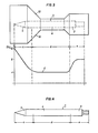
- Fig. 1 shows an example of a sabot projectile with penetrator and sabot, the penetrator being shown in axial section.
- Fig. 2 shows a diagram of the strength and toughness of a penetrator over the length of the same.
- 3 shows an example of cold forging a penetrator with a diagram of the degree of forging over the length of the penetrator.
- Fig. 4 shows a penetrator made of uranium alloys.
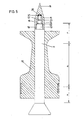
- 5 shows a penetrator with a pre-core.
- Fig. 1 shows a sabot projectile.
- the penetrator 1 has a tip 2, a rear 3 and a middle part 4.
- a guide device 5 is connected, which is formed by wings made of a specifically lighter material, such as aluminum, and stabilizes during flight.
- This guide device 5 is screwed, for example, into a thread 8 of the penetrator.
- the penetrator 1 is equipped with a screw thread 9 or grooves, on which or which a sabot 6 is applied.
- This sabot 6 is guided in the gun barrel and can have guide rings 7.
- the propellant charge of the gun acts on the rear end face 6 'of this sabot and on the rear 3 of the penetrator.
- the sabot 6 separates from the penetrator and the penetrator 1 continues to fly alone.
- the penetrator 1 consists of heavy metal, which increases its impact force.
- FIG. 2 shows the strength diagram of a penetrator 1 formed from tungsten heavy metal or uranium.
- the values for the strength in N / mm 2 and the Vickers hardness HV 30 are plotted on the left ordinate over the length of the penetrator 1.
- the toughness (elongation at break d 5 in%) is plotted on the right ordinate.
- the fully marked curve a shows the strength and the Vickers hardness and the dashed curve b shows the elongation at break in the various areas of the length of the penetrator 1.
- the tip area is designated c, the middle area d and the rear area e.
- the strength at the tip 2 reaches a value of 1290 N / mm 2 , which corresponds to a Vickers hardness HV 30 of 400.
- the hardness decreases from the tip 2 over the tip area c and reaches a value of 800 N / mm 2 in the middle area d, which corresponds to a Vickers hardness HV 30 of 250.
- the strength increases again in the rear region e and reaches a value of 1095 N / mm 2 at the rear 3, which corresponds to a Vickers hardness HV 30 of 340.
- the elongation at break (curve b) is 2 - 3% at the tip and increases in the tip area c up to the middle area d.
- the elongation at break is 20% in the central region d. From the central area d, the elongation at break drops again over the rear area e and reaches a value of 12% at the rear 3.
- FIG. 3 shows the cold forging of a blank, for example made of tungsten heavy metal. Since the finished penetrator 1 over its length should have the same diameter, it is assumed that a blank has a larger diameter in the areas in which a greater degree of forging or degree of deformation is to be achieved than in the areas in which only a lower degree of forging or degree of deformation is achieved should.
- the lines 10 indicate the outline of the blank in the tip area c, middle area d and rear area e, the diameter differences of the blank being exaggerated for the sake of clarity.
- the penetrator 1 is drawn within the lines 10, the tip of which is again designated by 2, the rear of which is designated by 3 and the central part thereof by 4.
- This blank is cold forged and curve f shows the degree of forging or degree of deformation.
- the degree of forging is 12%.
- the degree of forging decreases in area c and the degree of forging is 4% in central area d. Starting from the central area d, the degree of forging increases in the rear area e and amounts to 8% at the rear.
- Fig. 4 shows a penetrator made of an alloy of depleted uranium.
- the heat treatment takes place in the tip area c at 450 ° C., in the middle area d at 200 ° C. and in the rear area e at 370 ° C.
- the heat treatment takes place in the tip area c at 370 ° C, in the middle area d at 550 ° C and in the rear area e at 430 ° C.
- FIG. 5 shows a penetrator with a pre-core.
- 11 is the penetrator and 12 is the sabot.
- Two front cores 14 and 15 are connected to the front end 3 of the penetrator. These pre-cores are supported against a surface 16 which is perpendicular to the axis of the penetrator 11.
- 18 is a slippery hood made of aluminum, which by means of a Thread 19 is screwed onto the front end 13 of the penetrator.
- the second pre-core 15 has a central projection 20 which is surrounded by a rubber ring 21, for example an O-ring.
- the pre-cores 14 and 15 are supported against the hood 18 and in this way the pre-cores 14 and 15 are held on the penetrator 11 by the screwed-on aluminum hood 8 during transport of the projectile and during its flight.
- the support surface 16 of the penetrator 11 and the support surface 17 of the first pre-core 14 have a protruding edge bead 22 or 23, so that the pre-core 14 is centered with respect to the front end 13 of the penetrator and the second pre-core 15 with respect to the first pre-core 14.
Landscapes
- Engineering & Computer Science (AREA)
- General Engineering & Computer Science (AREA)
- Chemical & Material Sciences (AREA)
- Combustion & Propulsion (AREA)
- Powder Metallurgy (AREA)
- Paper (AREA)
- Electrical Discharge Machining, Electrochemical Machining, And Combined Machining (AREA)
- Manufacture Of Motors, Generators (AREA)
- Replacement Of Web Rolls (AREA)
- Fish Paste Products (AREA)
- Jib Cranes (AREA)
- Confectionery (AREA)
- Drilling Tools (AREA)
- Earth Drilling (AREA)
Applications Claiming Priority (8)
| Application Number | Priority Date | Filing Date | Title |
|---|---|---|---|
| AT4114/83 | 1983-11-23 | ||
| AT411483 | 1983-11-23 | ||
| AT1324/84 | 1984-04-19 | ||
| AT132484 | 1984-04-19 | ||
| AT132384 | 1984-04-19 | ||
| AT1323/84 | 1984-04-19 | ||
| AT177484 | 1984-05-29 | ||
| AT1774/84 | 1984-05-29 |
Publications (3)
| Publication Number | Publication Date |
|---|---|
| EP0143775A2 true EP0143775A2 (fr) | 1985-06-05 |
| EP0143775A3 EP0143775A3 (en) | 1986-06-25 |
| EP0143775B1 EP0143775B1 (fr) | 1989-01-11 |
Family
ID=27421498
Family Applications (1)
| Application Number | Title | Priority Date | Filing Date |
|---|---|---|---|
| EP84890215A Expired EP0143775B1 (fr) | 1983-11-23 | 1984-11-14 | Projectile perforant sous-calibré et son procédé de fabrication |
Country Status (7)
| Country | Link |
|---|---|
| US (1) | US4665828A (fr) |
| EP (1) | EP0143775B1 (fr) |
| AT (1) | ATE40006T1 (fr) |
| BR (1) | BR8405954A (fr) |
| DE (1) | DE3476117D1 (fr) |
| ES (1) | ES8606037A1 (fr) |
| IL (1) | IL73583A (fr) |
Cited By (10)
| Publication number | Priority date | Publication date | Assignee | Title |
|---|---|---|---|---|
| DE3705382A1 (de) * | 1987-02-20 | 1988-09-01 | Diehl Gmbh & Co | Penetrator und verfahren zu seiner herstellung |
| EP0266557A3 (fr) * | 1986-10-09 | 1989-12-06 | DIEHL GMBH & CO. | Revêtement pour charge creuse, en particulier pénétrateur ou corps à effet cinétique pour projectiles |
| FR2652412A1 (fr) * | 1989-09-28 | 1991-03-29 | Rheinmetall Gmbh | Procede pour la mise au point des caracteristiques mecaniques d'un corps de projectile en metal lourd ainsi qu'un corps de projectile obtenu par ce procede. |
| DE3723909A1 (de) * | 1987-07-18 | 1991-12-05 | Rheinmetall Gmbh | Penetrator |
| FR2664039A1 (fr) * | 1990-07-02 | 1992-01-03 | Sauvestre Jean Claude | Alliages mixtes organiques-metalliques pour realisation de projectiles. |
| DE4023482A1 (de) * | 1990-07-24 | 1992-01-30 | Rheinmetall Gmbh | Unterkalibriges wuchtgeschoss |
| EP0349446B1 (fr) * | 1988-06-22 | 1992-12-16 | Cime Bocuze | Procédé de mise en forme directe et d'optimisation des caractéristiques mécaniques de projectiles perforants en alliage de tungstène à haute densité |
| DE10231777A1 (de) * | 2002-07-13 | 2004-02-05 | Diehl Munitionssysteme Gmbh & Co. Kg | Verfahren zur Herstellung eines Wolfram-Basismaterials und Verwendung desselben |
| WO2017060118A1 (fr) * | 2015-10-06 | 2017-04-13 | Rheinmetall Waffe Munition Gmbh | Pénétrateur et projectile sous-calibré |
| WO2022028795A1 (fr) * | 2020-08-06 | 2022-02-10 | Rheinmetall Waffe Munition Gmbh | Pénétrateur, utilisation d'un pénétrateur et projectile |
Families Citing this family (16)
| Publication number | Priority date | Publication date | Assignee | Title |
|---|---|---|---|---|
| US4722825A (en) * | 1987-07-01 | 1988-02-02 | The United States Of America As Represented By The Secretary Of The Navy | Method of fabricating a metal/ceramic composite structure |
| DE3821474C1 (de) * | 1988-06-25 | 1998-08-27 | Nwm De Kruithoorn Bv | Unterkalibriges, drallstabilisiertes Mehrzweckgeschoß |
| US5078054A (en) * | 1989-03-14 | 1992-01-07 | Olin Corporation | Frangible projectile |
| US4940404A (en) * | 1989-04-13 | 1990-07-10 | Westinghouse Electric Corp. | Method of making a high velocity armor penetrator |
| DE3926711C2 (de) * | 1989-08-12 | 1995-12-07 | Rheinmetall Ind Gmbh | Geschoß mit Innenraum |
| DE3929015A1 (de) * | 1989-09-01 | 1991-03-14 | Diehl Gmbh & Co | Unterkalibriges uebungsgeschoss |
| DE19619341C2 (de) * | 1996-05-14 | 1999-11-11 | Rheinmetall W & M Gmbh | Unterkalibriges Wuchtgeschoß und Verfahren zu seiner Herstellung |
| USD441826S1 (en) | 2000-03-21 | 2001-05-08 | Lockheed Martin Corporation | Sharpened nose penetrator |
| CZ20032719A3 (cs) * | 2001-03-13 | 2004-03-17 | Robert Frederick Bunney | Palná zbraň |
| US7243588B2 (en) * | 2001-05-15 | 2007-07-17 | Doris Nebel Beal Inter Vivos Patent Trust | Power-based core for ammunition projective |
| WO2003104742A2 (fr) * | 2001-05-15 | 2003-12-18 | Beal Harold F | Formation in situ d'un bouchon pour balle de munition |
| US20040055501A1 (en) * | 2002-09-20 | 2004-03-25 | Hunn David L. | Penetrator and method for using same |
| RU2258891C1 (ru) * | 2004-02-02 | 2005-08-20 | Закрытое Акционерное Общество "Дальневосточная Технология" (Зао "Дв-Технология") | Твердосплавный сердечник бронебойной пули и способ его изготовления (варианты) |
| FR2987891B1 (fr) * | 2012-03-06 | 2014-09-26 | Nexter Munitions | Projectile sous calibre a structure de tete amenagee |
| DE102013212528A1 (de) * | 2013-06-27 | 2014-12-31 | Robert Bosch Gmbh | Verfahren zur Herstellung eines Stahlformkörpers |
| DE202015004089U1 (de) | 2015-06-02 | 2015-08-04 | Bundesrepublik Deutschland, vertreten durch das Bundesministerium der Verteidigung, dieses vertreten durch das Bundesamt für Ausrüstung, Informationstechnik und Nutzung der Bundeswehr | Penetrator |
Family Cites Families (18)
| Publication number | Priority date | Publication date | Assignee | Title |
|---|---|---|---|---|
| FR363305A (fr) * | 1906-02-15 | 1906-07-26 | Elias Mattison Johnson | Projectile d'artillerie pour perforer les cuirasses, et son mode de fabrication |
| FR829623A (fr) * | 1937-10-05 | 1938-07-01 | Acieries De Champagnole | Procédé d'établissement de projectiles à grande puissance de perforation et produits nouveaux en résultant |
| US2401483A (en) * | 1940-07-31 | 1946-06-04 | Mallory & Co Inc P R | Projectile and method of making the same |
| US2393648A (en) * | 1942-02-20 | 1946-01-29 | Carl A Martin | Projectile |
| US2435095A (en) * | 1942-06-24 | 1948-01-27 | Harry J Nichols | Projectile |
| FR1231010A (fr) * | 1950-12-29 | 1960-09-26 | Cie Ind Des Metaux Electroniqu | Projectiles à corps ou noyau composite et leur procédé de fabrication |
| US2922366A (en) * | 1956-05-22 | 1960-01-26 | Lyon George Albert | Projectile nose structure |
| FR1212390A (fr) * | 1959-05-26 | 1960-03-23 | Emploi de nouveaux matériaux pour éléments de munitions et procédés d'obtention de ces éléments | |
| US3302570A (en) * | 1965-07-23 | 1967-02-07 | Walter G Finch | Armor piercing, fragmenting and incendiary projectile |
| US3880083A (en) * | 1967-05-19 | 1975-04-29 | Us Army | Bimetallic mass stabilized flechette |
| LU56486A1 (fr) * | 1968-07-15 | 1969-05-21 | ||
| BE794801A (fr) * | 1972-01-31 | 1973-07-31 | Int Nickel Ltd | Procede de recuit en zones d'alliages |
| GB1514908A (en) * | 1974-01-22 | 1978-06-21 | Mallory Metallurg Prod Ltd | Armour piercing projectiles |
| CH627549A5 (de) * | 1977-11-28 | 1982-01-15 | Oerlikon Buehrle Ag | Verfahren zur herstellung eines panzerbrechenden geschosses. |
| FR2490805B1 (fr) * | 1980-09-23 | 1985-10-31 | France Etat | Projectile empenne du type fleche |
| US4458599A (en) * | 1981-04-02 | 1984-07-10 | Gte Products Corporation | Frangible tungsten penetrator |
| DE3209593A1 (de) * | 1982-03-17 | 1983-09-29 | Rheinmetall GmbH, 4000 Düsseldorf | Unterkalibriges panzerbrechendes wuchtgeschoss (penetrator) |
| US4428295A (en) * | 1982-05-03 | 1984-01-31 | Olin Corporation | High density shot |
-
1984
- 1984-11-14 EP EP84890215A patent/EP0143775B1/fr not_active Expired
- 1984-11-14 DE DE8484890215T patent/DE3476117D1/de not_active Expired
- 1984-11-14 AT AT84890215T patent/ATE40006T1/de not_active IP Right Cessation
- 1984-11-21 IL IL73583A patent/IL73583A/xx unknown
- 1984-11-22 ES ES537862A patent/ES8606037A1/es not_active Expired
- 1984-11-22 BR BR8405954A patent/BR8405954A/pt unknown
- 1984-11-23 US US06/674,170 patent/US4665828A/en not_active Expired - Fee Related
Cited By (16)
| Publication number | Priority date | Publication date | Assignee | Title |
|---|---|---|---|---|
| EP0266557A3 (fr) * | 1986-10-09 | 1989-12-06 | DIEHL GMBH & CO. | Revêtement pour charge creuse, en particulier pénétrateur ou corps à effet cinétique pour projectiles |
| EP0279440A3 (fr) * | 1987-02-20 | 1989-08-16 | DIEHL GMBH & CO. | Pénétrateur et son procédé de fabrication |
| DE3705382A1 (de) * | 1987-02-20 | 1988-09-01 | Diehl Gmbh & Co | Penetrator und verfahren zu seiner herstellung |
| DE3723909A1 (de) * | 1987-07-18 | 1991-12-05 | Rheinmetall Gmbh | Penetrator |
| EP0349446B1 (fr) * | 1988-06-22 | 1992-12-16 | Cime Bocuze | Procédé de mise en forme directe et d'optimisation des caractéristiques mécaniques de projectiles perforants en alliage de tungstène à haute densité |
| FR2652412A1 (fr) * | 1989-09-28 | 1991-03-29 | Rheinmetall Gmbh | Procede pour la mise au point des caracteristiques mecaniques d'un corps de projectile en metal lourd ainsi qu'un corps de projectile obtenu par ce procede. |
| DE3932383A1 (de) * | 1989-09-28 | 1991-04-11 | Rheinmetall Gmbh | Geschosskoerper |
| FR2664039A1 (fr) * | 1990-07-02 | 1992-01-03 | Sauvestre Jean Claude | Alliages mixtes organiques-metalliques pour realisation de projectiles. |
| WO1992000499A1 (fr) * | 1990-07-02 | 1992-01-09 | Sauvestre Jean Claude | Alliages mixtes organiques-metalliques pour realisation de projectiles |
| DE4023482A1 (de) * | 1990-07-24 | 1992-01-30 | Rheinmetall Gmbh | Unterkalibriges wuchtgeschoss |
| DE10231777A1 (de) * | 2002-07-13 | 2004-02-05 | Diehl Munitionssysteme Gmbh & Co. Kg | Verfahren zur Herstellung eines Wolfram-Basismaterials und Verwendung desselben |
| WO2017060118A1 (fr) * | 2015-10-06 | 2017-04-13 | Rheinmetall Waffe Munition Gmbh | Pénétrateur et projectile sous-calibré |
| US11320246B2 (en) | 2015-10-06 | 2022-05-03 | Rheinmetall Waffe Munition Gmbh | Penetrator and sub-caliber projectile |
| IL258307B (en) * | 2015-10-06 | 2022-07-01 | Rheinmetall Waffe Munition Gmbh | Penetrator and sub-caliber projectile |
| WO2022028795A1 (fr) * | 2020-08-06 | 2022-02-10 | Rheinmetall Waffe Munition Gmbh | Pénétrateur, utilisation d'un pénétrateur et projectile |
| US12123688B2 (en) | 2020-08-06 | 2024-10-22 | Rheinmetall Waffe Munition Gmbh | Penetrator, use of a penetrator, and projectile |
Also Published As
| Publication number | Publication date |
|---|---|
| EP0143775A3 (en) | 1986-06-25 |
| BR8405954A (pt) | 1985-09-17 |
| ES537862A0 (es) | 1986-04-01 |
| US4665828A (en) | 1987-05-19 |
| ES8606037A1 (es) | 1986-04-01 |
| DE3476117D1 (en) | 1989-02-16 |
| IL73583A (en) | 1990-12-23 |
| ATE40006T1 (de) | 1989-01-15 |
| EP0143775B1 (fr) | 1989-01-11 |
Similar Documents
| Publication | Publication Date | Title |
|---|---|---|
| EP0143775A2 (fr) | Projectile perforant sous-calibré et son procédé de fabrication | |
| DE2234219C1 (de) | Panzerbrechendes Geschoß | |
| DE60010884T2 (de) | Expansionsgeschoss | |
| DE2727970C2 (fr) | ||
| DE2703638C2 (fr) | ||
| DE102009011093A1 (de) | Teilzerlegungsgeschoss für Jagdzwecke | |
| DE3525854A1 (de) | Fluegelstabilisiertes pfeilgeschoss | |
| DE1149638B (de) | Panzergranate fuer Waffen kleinen Kalibers | |
| EP0088898B1 (fr) | Projectile de calibre réduit à noyau perforant | |
| DE3037560A1 (de) | Panzerbrechendes geschoss | |
| DE68924336T2 (de) | Geschoss für Panzerbekämpfung mit Stacheln bildendem Kern. | |
| DE2557676A1 (de) | Splittergeschoss | |
| DE3617415A1 (de) | Unterkalibriges treibspiegelgeschoss | |
| DE1453811B1 (de) | Panzergranate | |
| DE3821474C1 (de) | Unterkalibriges, drallstabilisiertes Mehrzweckgeschoß | |
| WO2001018483A1 (fr) | Projectile de carabine pour la chasse a teneur en plomb reduite ou sans plomb, presentant une force de retention du noyau dans la chemise amelioree | |
| DE2422085A1 (de) | Uebungsgeschoss fuer schusswaffen | |
| DE102007037738A1 (de) | Geschoss mit einem Führungskäfig und Pusherplatte mit beschleunigungsoptimierter Öffnung | |
| DE3339078A1 (de) | Fluegelstabilisiertes unterkalibergeschoss grossen laenge/durchmesser-verhaeltnisses | |
| DE102004035385A1 (de) | Teilzerlegungsgeschoss mit massivem Kern und Kern aus gepresstem Pulver | |
| EP0221917A1 (fr) | Projectile sous-calibre. | |
| EP3742106B1 (fr) | Pénétrateur, utilisation d'un pénétrateur et projectile | |
| DE309293C (fr) | ||
| DE211778C (fr) | ||
| EP0987513B1 (fr) | Projectile sous-calibré |
Legal Events
| Date | Code | Title | Description |
|---|---|---|---|
| PUAI | Public reference made under article 153(3) epc to a published international application that has entered the european phase |
Free format text: ORIGINAL CODE: 0009012 |
|
| AK | Designated contracting states |
Designated state(s): AT BE DE FR GB SE |
|
| RTI1 | Title (correction) | ||
| PUAL | Search report despatched |
Free format text: ORIGINAL CODE: 0009013 |
|
| AK | Designated contracting states |
Kind code of ref document: A3 Designated state(s): AT BE DE FR GB SE |
|
| 17P | Request for examination filed |
Effective date: 19860701 |
|
| 17Q | First examination report despatched |
Effective date: 19870624 |
|
| GRAA | (expected) grant |
Free format text: ORIGINAL CODE: 0009210 |
|
| AK | Designated contracting states |
Kind code of ref document: B1 Designated state(s): AT BE DE FR GB SE |
|
| REF | Corresponds to: |
Ref document number: 40006 Country of ref document: AT Date of ref document: 19890115 Kind code of ref document: T |
|
| GBT | Gb: translation of ep patent filed (gb section 77(6)(a)/1977) | ||
| REF | Corresponds to: |
Ref document number: 3476117 Country of ref document: DE Date of ref document: 19890216 |
|
| ET | Fr: translation filed | ||
| PGFP | Annual fee paid to national office [announced via postgrant information from national office to epo] |
Ref country code: FR Payment date: 19891016 Year of fee payment: 6 |
|
| PGFP | Annual fee paid to national office [announced via postgrant information from national office to epo] |
Ref country code: DE Payment date: 19891018 Year of fee payment: 6 |
|
| PGFP | Annual fee paid to national office [announced via postgrant information from national office to epo] |
Ref country code: BE Payment date: 19891019 Year of fee payment: 6 |
|
| PGFP | Annual fee paid to national office [announced via postgrant information from national office to epo] |
Ref country code: AT Payment date: 19891020 Year of fee payment: 6 |
|
| PGFP | Annual fee paid to national office [announced via postgrant information from national office to epo] |
Ref country code: SE Payment date: 19891023 Year of fee payment: 6 |
|
| PGFP | Annual fee paid to national office [announced via postgrant information from national office to epo] |
Ref country code: GB Payment date: 19891031 Year of fee payment: 6 |
|
| PLBE | No opposition filed within time limit |
Free format text: ORIGINAL CODE: 0009261 |
|
| STAA | Information on the status of an ep patent application or granted ep patent |
Free format text: STATUS: NO OPPOSITION FILED WITHIN TIME LIMIT |
|
| 26N | No opposition filed | ||
| PG25 | Lapsed in a contracting state [announced via postgrant information from national office to epo] |
Ref country code: GB Effective date: 19901114 Ref country code: AT Effective date: 19901114 |
|
| PG25 | Lapsed in a contracting state [announced via postgrant information from national office to epo] |
Ref country code: SE Effective date: 19901115 |
|
| PG25 | Lapsed in a contracting state [announced via postgrant information from national office to epo] |
Ref country code: BE Effective date: 19901130 |
|
| BERE | Be: lapsed |
Owner name: VOEST-ALPINE A.G. Effective date: 19901130 |
|
| GBPC | Gb: european patent ceased through non-payment of renewal fee | ||
| PG25 | Lapsed in a contracting state [announced via postgrant information from national office to epo] |
Ref country code: FR Effective date: 19910731 |
|
| PG25 | Lapsed in a contracting state [announced via postgrant information from national office to epo] |
Ref country code: DE Effective date: 19910801 |
|
| REG | Reference to a national code |
Ref country code: FR Ref legal event code: ST |
|
| EUG | Se: european patent has lapsed |
Ref document number: 84890215.1 Effective date: 19910705 |