EP0143882A1 - Procédé pour appliquer un profil d'arête "soft"-formé, émulsionné avec une bande de recouvrement à une plaque et appareil pour le découpage de la bande - Google Patents
Procédé pour appliquer un profil d'arête "soft"-formé, émulsionné avec une bande de recouvrement à une plaque et appareil pour le découpage de la bande Download PDFInfo
- Publication number
- EP0143882A1 EP0143882A1 EP19840108298 EP84108298A EP0143882A1 EP 0143882 A1 EP0143882 A1 EP 0143882A1 EP 19840108298 EP19840108298 EP 19840108298 EP 84108298 A EP84108298 A EP 84108298A EP 0143882 A1 EP0143882 A1 EP 0143882A1
- Authority
- EP
- European Patent Office
- Prior art keywords
- edge
- workpiece
- knife
- cutting
- edges
- Prior art date
- Legal status (The legal status is an assumption and is not a legal conclusion. Google has not performed a legal analysis and makes no representation as to the accuracy of the status listed.)
- Granted
Links
Images

Classifications
-
- B—PERFORMING OPERATIONS; TRANSPORTING
- B29—WORKING OF PLASTICS; WORKING OF SUBSTANCES IN A PLASTIC STATE IN GENERAL
- B29C—SHAPING OR JOINING OF PLASTICS; SHAPING OF MATERIAL IN A PLASTIC STATE, NOT OTHERWISE PROVIDED FOR; AFTER-TREATMENT OF THE SHAPED PRODUCTS, e.g. REPAIRING
- B29C63/00—Lining or sheathing, i.e. applying preformed layers or sheathings of plastics; Apparatus therefor
- B29C63/0004—Component parts, details or accessories; Auxiliary operations
-
- B—PERFORMING OPERATIONS; TRANSPORTING
- B29—WORKING OF PLASTICS; WORKING OF SUBSTANCES IN A PLASTIC STATE IN GENERAL
- B29C—SHAPING OR JOINING OF PLASTICS; SHAPING OF MATERIAL IN A PLASTIC STATE, NOT OTHERWISE PROVIDED FOR; AFTER-TREATMENT OF THE SHAPED PRODUCTS, e.g. REPAIRING
- B29C63/00—Lining or sheathing, i.e. applying preformed layers or sheathings of plastics; Apparatus therefor
- B29C63/0026—Lining or sheathing, i.e. applying preformed layers or sheathings of plastics; Apparatus therefor an edge face with strip material, e.g. a panel edge
Definitions
- the invention relates to a method for attaching a soft-shaped edge profile and a cover strip made of veneer wood or plastic thereon to the corners of square or rectangular plate-shaped workpieces made of wood or wood-like material according to the preamble of claim 1 and to a device for cutting off the cover strip on the workpiece corners according to the preamble of claim 2.
- the so-called soft-shaped edge profiles are mainly used for furniture front panels, which consist for example of a surface-coated chipboard material. These are edge profiles that smoothly merge into a flat visible surface of the furniture front panels, that is, at least towards the flat front of such furniture parts, have an area that has only a slight angle of inclination with respect to this flat front. Towards the narrow sides of the workpieces, the edge profiles can fall off with a larger angle of inclination, this angle of inclination being approximately perpendicular to the flat front of the workpieces in the end region.
- the course of the angle of inclination of the edge profile changes over the edge cross section of the plate-shaped workpieces, as a result of which 'convex, concave or alternating curvatures of the j edge profiles can be achieved.
- the protrusion of the corner strips last approached to the workpiece edges is milled away in the area of the workpiece corners using a form cutter, after which any protruding milling edges of the cover strip are pressed firmly against the workpiece corners using a pressing unit.
- the major disadvantage of this method is that despite the high machining accuracy of the milling and pressing units, the corner strips joined to the corners of the workpiece do not form a butt joint that runs exactly with the miter edge, but have an undefined course which affects the appearance of the finished furniture panels.
- the invention is therefore based on the object of improving the generic method for applying a soft-shaped edge profile and a cover strip thereon to the plate-shaped workpieces,
- This object is achieved in a generic method according to the invention in that first the one parallel workpiece edges are milled, then the transverse workpiece edges are milled and on the edge profile of the cover strip with a projection over the miter edges formed by the edge profiles converging on the workpiece corners and is cut off along the mitred edges and then approached to the edge profile of the first milled workpiece edges of the cover strips and is cut off along the mitred edges at the workpiece corners.
- the advantages achieved outweigh overall, because the cover strips can be cut and joined exactly in the miter direction in spite of any edge profile at the workpiece corners and no subsequent processing operations are necessary to overcast the workpiece corners. ! It is also avoided that the cover strips overlap at the workpiece corners and thus one cover strip would be glued to the other. Rather, the cover strips are only glued to the milled edge of the workpieces along the mitred edges. It also does no harm if the punching device leaves an incision in the sheet material along the profile edge, because this creates additional space for taking up a small material jam that can result at the cutting edges of the cover strips.
- a device can advantageously be used with which the cover strips on the workpiece corners can be cut off exactly along the profile edge between the converging edge profiles.
- An advantageous embodiment of such a device consists in that above a workpiece support perpendicular or inclined to the support plane there is arranged a cutting knife which is displaceable and can be aligned with the miter edge at the workpiece corners on the workpiece support, the contour of the cutter indicating the negative profile of the miter edge the workpiece corners.
- Another advantageous embodiment of the separating device results from a cutting knife which can be displaced vertically or at an angle to the supporting plane and can be aligned with the miter edge at the corners of the workpieces resting on the workpiece support, the cutting edge or the engaged cutting section of the knife being shorter than the cutting edge at the corner strips D along the mitred edge and the knife is parallel to the workpiece support guide in the direction of the mitred edge is displaceably mounted and deliverable to at least.
- Both the punching device and the cutting device can be integrated in a continuous machine. It is possible to guide the punching device or the cutting device with the workpieces and to return them to the starting position in the working cycle interval.
- the cutting device with the cutting knife has an advantage in that the punching knife has to be as long as the respective trimmed edge, the correspondingly long contour cutting edge a complicated cut, and a punching knife must be provided for each individually shaped edge profile.
- the cutting device with the cutting knife which can be moved along the miter edge, enables a simpler knife edge that can be used universally for all applications.
- this requires a more complex knife guide because the knife has to be moved along the cutting line.
- optimal cutting conditions can be achieved at any point on the cutting line, for example the shape of the knife edge can be easily adapted to very steep cutting contours.
- the cutting knife is guided and delivered by means of suitable auxiliary drives, which can be controlled via a program.
- FIG. 1 shows a plate-shaped workpiece 1 of rectangular basic shape, which consists of chipboard material and is provided on its top and underside with a surface cover layer, not specified.
- a so-called soft-form profile is already milled onto the parallel edges 2 and 3 of the workpiece 1, which ends flat in the flat upper side of the workpiece 1 and, viewed in the edge cross section, has alternating concave and convex curvatures.
- the edge profile which is identical on all edges 2, 3, falls more steeply.
- edges 2 and 3 of the workpiece 1 are milled in a continuous machine in what is known as longitudinal machining and transverse machining, firstly the mutually parallel edges 3, the so-called transverse edges of the workpiece 1, and then after rotating the workpiece 1 by 90 degrees to the so-called longitudinal edges 2 the edge profile is milled.
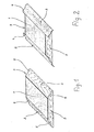
- a cover strip 4 is then approached to each of the last milled edges 2, which closely clings to the edge profile of the edge 2 and is immediately glued to it. This is shown in FIG. 2, which also makes it clear that the cover strips 4 protrude at both ends over the miter edge 5 (FIG. 1), which is formed by the edge profiles converging at the workpiece corners.
- the cover strips 4 are therefore punched out along the miter edges 5 at the corners of the workpiece 1, before a further cover strip is milled onto the first milled transverse edges 3, for which purpose a punching device 20 is used, which is shown schematically in FIG.
- An essential element of the punching device 20 is a punching knife 6 with a cutting edge 7, which is a shaped cutting edge. is formed and the negative contour represents the miter edges 5 of the workpiece 1.
- the knife 6 is displaceable perpendicular to the plane of the workpiece 1, which is so aligned with the relevant corner with its miter edge 5 on the knife edge 7; is that the contour of the knife edge 7 is arranged equidistantly from that of the respective profile edge 5. This can be ensured by a suitable support for workpiece 1 and appropriate stops. Then the punching knife 6 is moved down against the workpiece 1 until the respective protrusion of the cover strip 4 along the profile edge 5 is completely cut off.
- cover strips 4 Only when the cover strips 4 are punched out at both ends on the profiled longitudinal edges 2 of the workpiece 1 are the two further cover strips 4 approached to the first milled transverse edges 3 of the workpiece 1.
- the cover strips 4 which have been driven onto the profile of the transverse edges 3 initially protrude at both ends over the miter edges 5 on the workpiece corners and are punched out along the miter edges 5 in a manner analogous to the cover strips 4 on the workpiece longitudinal edges 2.
- This can be done with the same or with of a further punching device 20, the punching device 20 in question, according to the exemplary embodiment, being part of a continuous machine 10 shown in FIG. 5 or as a separate processing unit.
- a conveyor belt or a conveyor chain 11 which serves as a support for the plate-shaped workpieces 1 and is driven continuously.
- the workpieces 1 can be clamped on the conveyor chain 11 so that they are precisely aligned on all processing units of the continuous machine 10.
- a traveling support device for the workpieces 1 can also be provided above the conveyor chain 11; but which is not shown in the drawing.
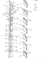
- the machine 10 When viewed in the direction of travel, the machine 10 first has a milling device 11, which comprises two oppositely driven form cutters 12, by means of which the soft-form profile is milled onto the edge of the workpieces 1 passing by. This is followed by a station 13 for specifying the cover strip 4 on the profiled edge of the workpiece 1 in question.
- the cover strip 4 is pulled from an magazine 28 by an endless advance and is first moved to the relevant edge of the workpiece 1 in a vertical, level orientation by means of pressure rollers 14 .
- a subsequent pressing device 15 has a multiplicity of pressure rollers 16 which are aligned in accordance with the edge profile of the workpieces 1 in order to nestle the cover strip 4 against the edge profile of the workpiece 1.
- the workpieces 1 cross-cut stations 16, which are perpendicular to Crosscut saw blades 17 are provided, by means of which the cover strip 4 is cut to length approximately in alignment with the transverse edges which are perpendicular to the workpiece edge to be machined.
- the cover strip then projects beyond the miter edge 5 at the workpiece corners, as shown in FIG. 2.
- cover strip 4 is then milled flush on the workpiece edge to be machined on the top and bottom of the workpiece by means of suitable cutters 19.
- the workpiece 1 passes the punching device 20,; which is also shown in Figure 4 in its essential elements.
- the punching knife is seated in a suitable tool holder 25, which is guided over a push rod 21, which is designed as a piston rod of a hydraulic cylinder 22.
- This cylinder 11 sits on a carriage 23 which is mounted on longitudinal guides 24 parallel to the transport chain 11.
- Two such punching devices 20 are expediently seated on the longitudinal guides 24 in order to be able to machine both corners of the workpiece 1 on the coated edge at the same time.
- the slides 23 are carried in synchronism with the respective workpiece 1 on the transport chain 11 during the punching process in order to run back into a starting position against the conveying direction in the interval between the working cycles.
- the punching devices 20 are followed by a further pressing station 26 with pressure rollers 27 which, from above, coat that section of the cover strip 4 Profile edge press, the flat adjoins the flat upper surface of the workpieces 1, in order in particular to the workpiece corners out again corner strips for a particular i intimate connection between the adhesive D 4 and the milled material of the workpieces 1 to be ensured.
- the punching devices 20 can be aligned to any miter angle. Since the miters or here the miter edges 5 on the workpiece corners are generally in the direction of the bisector of the corner angles, the punching devices 20 on the right-angled workpieces 1 are set up for a 45-degree miter and are in accordance with the direction of the knife edges 7 (FIG. 4) at an angle of 45 degrees to the direction of travel of the workpieces 1.
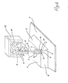
- a knife device with a cutting knife can be used, as will be described in more detail below with reference to FIG. 6.
- a workpiece support 1 can be seen in FIG. 6, which can be a conveyor belt, a conveyor chain or a table and which is preferably oriented horizontally.
- plate-shaped workpieces 2 are placed below a processing station, which are equipped on their narrow sides with so-called soft-shaped edge profiles. These are edge profiles which smoothly merge into the flat front of the workpieces 2, that is to say have an area towards this front of the workpieces 2 which has only a slight inclination to the plane of the workpiece front side.
- the edge profiles with a larger angle of inclination can even be approximately perpendicular to the plane front of the workpieces 2.
- the course of the angle of inclination of the edge profiles can also change across the edge cross section, as a result of which convex, concave; or alternate curvatures of the edge profiles can be achieved.
- Cover strips 3 which nestle against the edge profile, are approached to the soft-shaped narrow sides of the workpieces 2 by means of a device (not shown in the drawing).
- the cover strips 3 initially protrude in their longitudinal direction before they are cut off along the miter edge 4 formed in the area of the right-angled edge profiles 4.
- the excess of the cover strips 3 is separated off exactly at the miter edge 4 by means of a knife 5 which is guided along the miter edge 4, which on the one hand causes a movement of the knife 5 in the direction of the bisector of the relevant corner of the workpiece 2 and on the other hand an infeed of the knife 5 towards the workpiece support 1 corresponding to the drop in the edge profile from the front of the workpieces 2. This is accomplished with the device discussed in more detail below.
- the knife 5 can have a fixed cutting edge 6 or a cutting roller which is guided exactly along the cutting line at the miter edge 4.
- the knife 5 is seated in a knife holder 7 which, as indicated by the arrow A, is vertically displaceable relative to the workpiece support 1.
- the knife holder 7 is connected via a guide rod 8 to a lifting device 9 which acts on the knife holder 7 and thus the knife 5 during the cutting process in the direction of the workpiece support 1.
- the lifting device 9 is seated on a cross support 10, which is mounted in a two-dimensionally displaceable manner on guides 11 and 12 which are perpendicular to one another. This is illustrated by arrows B and C.
- the knife 5 can be moved in any direction in the direction of a parallel plane to the workpiece support 1, while on the other hand the infeed takes place perpendicular to the plane of the workpiece support 1 via the lifting device 9.
- the knife 5, the cutting edge 6 of which extends in the direction of the miter edge 4 only over a fraction of the length of the cutting line, can be moved along the miter edge 4 falling off the top of the workpieces 2.
- additional guide elements 14 which project downward parallel to the knife 5. They carry on their lower ends support rollers 15 or runners which are supported on the workpiece 2 during the cutting process along a line parallel to the miter edge 4.
- the depth of cut of the knife edge 6 can be specified via these support rollers 15, wherein at least when the support rollers 15 are arranged very close to the knife edge 6, they are set back approximately by the depth of cut with respect to the edge 6. If the distance between the support rollers 15 and the cutting edge 6 is greater, a different offset between the knife edge 6 and the support rollers 15 may also be necessary in accordance with the sloping contours of the narrow side of the workpiece 2 in question.
- the support rollers 15 can also take over the function of pressing the cover strips 3 along the cut edge at the miter edge 4. Regardless, can too Seen in the cutting direction of the knife 5, a separate pressure roller must be provided behind the knife edge 6 for this purpose, which must have a lateral offset with respect to the cutting line in order to be able to grasp the cut cover strip 3 reaching the miter edge 4. This pressure roller arranged behind the knife 5 is not shown in the drawing.
Landscapes
- Engineering & Computer Science (AREA)
- Manufacturing & Machinery (AREA)
- Perforating, Stamping-Out Or Severing By Means Other Than Cutting (AREA)
- Manufacture Of Wood Veneers (AREA)
Applications Claiming Priority (4)
| Application Number | Priority Date | Filing Date | Title |
|---|---|---|---|
| DE19833336275 DE3336275C2 (de) | 1983-10-05 | 1983-10-05 | Verfahren zur Anbringung eines mit einem Deckstreifen beschichteten, soft-geformten Kantenprofils an plattenförmige Werkstücke und Vorrichtung zum Abschneiden des Deckstreifens |
| DE3336275 | 1983-10-05 | ||
| DE19833344512 DE3344512A1 (de) | 1983-10-05 | 1983-12-09 | Vorrichtung zum abschneiden von deckstreifen an softgeformten kantenprofilen plattenfoermiger werkstuecke |
| DE3344512 | 1983-12-09 |
Publications (2)
| Publication Number | Publication Date |
|---|---|
| EP0143882A1 true EP0143882A1 (fr) | 1985-06-12 |
| EP0143882B1 EP0143882B1 (fr) | 1988-11-23 |
Family
ID=25814641
Family Applications (1)
| Application Number | Title | Priority Date | Filing Date |
|---|---|---|---|
| EP19840108298 Expired EP0143882B1 (fr) | 1983-10-05 | 1984-07-14 | Procédé pour appliquer un profil d'arête "soft"-formé, émulsionné avec une bande de recouvrement à une plaque et appareil pour le découpage de la bande |
Country Status (2)
| Country | Link |
|---|---|
| EP (1) | EP0143882B1 (fr) |
| DE (1) | DE3344512A1 (fr) |
Cited By (2)
| Publication number | Priority date | Publication date | Assignee | Title |
|---|---|---|---|---|
| EP2067603A3 (fr) * | 2007-12-04 | 2009-08-12 | Jowat AG | Procédé de scellement d'un substrat en forme de plaque et pièces fabriquées selon ce procédé |
| WO2009109302A1 (fr) * | 2008-03-03 | 2009-09-11 | Düspohl Maschinenbau Gmbh | Procédé et appareil destiné à fabriquer des éléments profilés revêtus |
Families Citing this family (1)
| Publication number | Priority date | Publication date | Assignee | Title |
|---|---|---|---|---|
| DE3926161C3 (de) * | 1989-08-08 | 1998-12-24 | Vd Werkstaetten Gmbh & Co Kg | Verfahren zur Herstellung einer im Kantenbereich profilierten Möbelplatte |
Citations (3)
| Publication number | Priority date | Publication date | Assignee | Title |
|---|---|---|---|---|
| DE1919102A1 (de) * | 1969-04-15 | 1970-10-22 | Raimann Gmbh B | Kappvorrichtung fuer Fumierkanten |
| DE2810565A1 (de) * | 1978-03-11 | 1979-09-20 | Ott Paul Gmbh & Co Kg | Kantenanleimmaschine |
| DE3111985A1 (de) * | 1981-03-26 | 1982-10-07 | Hornberger Maschinenbaugesellschaft mbH & Co KG, 7294 Schopfloch | Vorrichtung zum verschraenken der furnier- und kunststoffkanten |
-
1983
- 1983-12-09 DE DE19833344512 patent/DE3344512A1/de active Granted
-
1984
- 1984-07-14 EP EP19840108298 patent/EP0143882B1/fr not_active Expired
Patent Citations (3)
| Publication number | Priority date | Publication date | Assignee | Title |
|---|---|---|---|---|
| DE1919102A1 (de) * | 1969-04-15 | 1970-10-22 | Raimann Gmbh B | Kappvorrichtung fuer Fumierkanten |
| DE2810565A1 (de) * | 1978-03-11 | 1979-09-20 | Ott Paul Gmbh & Co Kg | Kantenanleimmaschine |
| DE3111985A1 (de) * | 1981-03-26 | 1982-10-07 | Hornberger Maschinenbaugesellschaft mbH & Co KG, 7294 Schopfloch | Vorrichtung zum verschraenken der furnier- und kunststoffkanten |
Cited By (4)
| Publication number | Priority date | Publication date | Assignee | Title |
|---|---|---|---|---|
| EP2067603A3 (fr) * | 2007-12-04 | 2009-08-12 | Jowat AG | Procédé de scellement d'un substrat en forme de plaque et pièces fabriquées selon ce procédé |
| WO2009109302A1 (fr) * | 2008-03-03 | 2009-09-11 | Düspohl Maschinenbau Gmbh | Procédé et appareil destiné à fabriquer des éléments profilés revêtus |
| RU2456160C2 (ru) * | 2008-03-03 | 2012-07-20 | Дюспол Машиненбау Гмбх | Способ и устройство для изготовления элементов профиля с покрытием |
| US8518200B2 (en) | 2008-03-03 | 2013-08-27 | Düspohl Maschinenbau Gmbh | Method and apparatus for manufacturing coated profile members |
Also Published As
| Publication number | Publication date |
|---|---|
| EP0143882B1 (fr) | 1988-11-23 |
| DE3344512C2 (fr) | 1988-09-01 |
| DE3344512A1 (de) | 1985-06-20 |
Similar Documents
| Publication | Publication Date | Title |
|---|---|---|
| DE19804787C2 (de) | Verfahren zum Herstellen faltbarer Faserplatten | |
| EP0184642A1 (fr) | Procédé pour produire des panneaux avec forages, de préférence en bois ou matière similaire, et installation pour exécuter ces procédés | |
| DE3020155C2 (de) | Besäumeinrichtung für plattenförmige Werkstücke mit überstehenden Deckschichten | |
| DE3925472C2 (de) | Verfahren und Vorrichtung zum Schneiden von Sandwichpaneelen | |
| DE4114895A1 (de) | Aufteilsaege | |
| DE3913765C2 (fr) | ||
| EP0143882B1 (fr) | Procédé pour appliquer un profil d'arête "soft"-formé, émulsionné avec une bande de recouvrement à une plaque et appareil pour le découpage de la bande | |
| EP0055793B1 (fr) | Dispositif pour le délignage de planches | |
| DE19503433C3 (de) | Vorrichtung und Verfahren zum Zuschneiden plattenförmiger Stränge | |
| DE3336275C2 (de) | Verfahren zur Anbringung eines mit einem Deckstreifen beschichteten, soft-geformten Kantenprofils an plattenförmige Werkstücke und Vorrichtung zum Abschneiden des Deckstreifens | |
| DE3607146A1 (de) | Verfahren und maschine zur bearbeitung von kanteln | |
| DE1921554C3 (de) | Maschine zum Herstellen von Gehrungsnuten in plattenförmige Werkstücke | |
| EP0394521B1 (fr) | Procédé et dispositif pour le découpage ou le délignage de pièces de bois ou similaires | |
| DE2540109B2 (de) | Kreissaege mit zwei gegenlaeufig angetriebenen saegeblaettern | |
| EP0221289B1 (fr) | Machine à travailler le bois, en particulier des poutres de fenêtre et des poutres similaires | |
| EP3684570B1 (fr) | Machine et procédé pour enduire des pièces | |
| DE4138734C2 (de) | Verfahren und Vorrichtung zur Bearbeitung beider Längsseiten von in Längsrichtung geförderten Schnitthölzern | |
| EP1652662A1 (fr) | Procédé et machine pour la fabrication de panneaux sandwich formatés | |
| DE2503985A1 (de) | Verfahren und vorrichtung zum schneiden von gegenstaenden aus holz o. dgl., insbesondere von zierleisten, tueren u. a. | |
| DE3546482A1 (de) | Werkstueckvorschubvorrichtung zum anbau an plattenaufteilmaschinen | |
| DE2253937C3 (de) | Verfahren zur Herstellung einer auf unterschiedliche Mauerdicken einstellbaren Türzarge sowie nach einem derartigen Verfahren hergestellte Türzarge | |
| DE3511957C2 (fr) | ||
| DE140163C (fr) | ||
| DE2056920C3 (de) | Vorrichtung zum Herstellen von in Gehrung geschnittene und mit Keilzinken versehene Stirnseiten aufweisenden stabförmigen Werkstücken | |
| DE2164920C3 (de) | Fräsmaschine zum Bearbeiten des Randes einer Platte |
Legal Events
| Date | Code | Title | Description |
|---|---|---|---|
| PUAI | Public reference made under article 153(3) epc to a published international application that has entered the european phase |
Free format text: ORIGINAL CODE: 0009012 |
|
| AK | Designated contracting states |
Designated state(s): BE DE FR GB IT NL SE |
|
| RBV | Designated contracting states (corrected) |
Designated state(s): BE FR GB IT NL SE |
|
| 17P | Request for examination filed |
Effective date: 19850503 |
|
| 17Q | First examination report despatched |
Effective date: 19860528 |
|
| D17Q | First examination report despatched (deleted) | ||
| GRAA | (expected) grant |
Free format text: ORIGINAL CODE: 0009210 |
|
| AK | Designated contracting states |
Kind code of ref document: B1 Designated state(s): BE FR GB IT NL SE |
|
| PG25 | Lapsed in a contracting state [announced via postgrant information from national office to epo] |
Ref country code: NL Effective date: 19881123 |
|
| ET | Fr: translation filed | ||
| ITF | It: translation for a ep patent filed | ||
| GBT | Gb: translation of ep patent filed (gb section 77(6)(a)/1977) | ||
| NLV1 | Nl: lapsed or annulled due to failure to fulfill the requirements of art. 29p and 29m of the patents act | ||
| PLBE | No opposition filed within time limit |
Free format text: ORIGINAL CODE: 0009261 |
|
| STAA | Information on the status of an ep patent application or granted ep patent |
Free format text: STATUS: NO OPPOSITION FILED WITHIN TIME LIMIT |
|
| 26N | No opposition filed | ||
| PGFP | Annual fee paid to national office [announced via postgrant information from national office to epo] |
Ref country code: SE Payment date: 19910612 Year of fee payment: 8 |
|
| PGFP | Annual fee paid to national office [announced via postgrant information from national office to epo] |
Ref country code: GB Payment date: 19910711 Year of fee payment: 8 |
|
| PGFP | Annual fee paid to national office [announced via postgrant information from national office to epo] |
Ref country code: BE Payment date: 19910715 Year of fee payment: 8 |
|
| PGFP | Annual fee paid to national office [announced via postgrant information from national office to epo] |
Ref country code: FR Payment date: 19910724 Year of fee payment: 8 |
|
| ITTA | It: last paid annual fee | ||
| PG25 | Lapsed in a contracting state [announced via postgrant information from national office to epo] |
Ref country code: GB Effective date: 19920714 |
|
| PG25 | Lapsed in a contracting state [announced via postgrant information from national office to epo] |
Ref country code: SE Effective date: 19920715 |
|
| PG25 | Lapsed in a contracting state [announced via postgrant information from national office to epo] |
Ref country code: BE Effective date: 19920731 |
|
| BERE | Be: lapsed |
Owner name: IMA-NORTE MASCHINENFABRIKEN KLESSMANN G.M.B.H. & Effective date: 19920731 |
|
| GBPC | Gb: european patent ceased through non-payment of renewal fee |
Effective date: 19920714 |
|
| PG25 | Lapsed in a contracting state [announced via postgrant information from national office to epo] |
Ref country code: FR Effective date: 19930331 |
|
| REG | Reference to a national code |
Ref country code: FR Ref legal event code: ST |
|
| EUG | Se: european patent has lapsed |
Ref document number: 84108298.5 Effective date: 19930204 |