EP0144056A2 - Système d'embrayage pour le dispositif de développement dans une machine à copier électrostatique - Google Patents
Système d'embrayage pour le dispositif de développement dans une machine à copier électrostatique Download PDFInfo
- Publication number
- EP0144056A2 EP0144056A2 EP84114330A EP84114330A EP0144056A2 EP 0144056 A2 EP0144056 A2 EP 0144056A2 EP 84114330 A EP84114330 A EP 84114330A EP 84114330 A EP84114330 A EP 84114330A EP 0144056 A2 EP0144056 A2 EP 0144056A2
- Authority
- EP
- European Patent Office
- Prior art keywords
- developing means
- copying machine
- engagement
- rotary drum
- accordance
- Prior art date
- Legal status (The legal status is an assumption and is not a legal conclusion. Google has not performed a legal analysis and makes no representation as to the accuracy of the status listed.)
- Granted
Links
- 108091008695 photoreceptors Proteins 0.000 claims abstract description 10
- 230000002093 peripheral effect Effects 0.000 claims description 4
- 239000002245 particle Substances 0.000 description 10
- 239000000470 constituent Substances 0.000 description 4
- 238000000926 separation method Methods 0.000 description 3
- 238000012546 transfer Methods 0.000 description 3
- 230000000694 effects Effects 0.000 description 2
- 230000013011 mating Effects 0.000 description 2
- 230000003287 optical effect Effects 0.000 description 2
- 238000005192 partition Methods 0.000 description 2
- 206010016275 Fear Diseases 0.000 description 1
- 238000013459 approach Methods 0.000 description 1
- 238000013461 design Methods 0.000 description 1
- 238000003780 insertion Methods 0.000 description 1
- 230000037431 insertion Effects 0.000 description 1
- 238000005259 measurement Methods 0.000 description 1
- 238000012986 modification Methods 0.000 description 1
- 230000004048 modification Effects 0.000 description 1
- 239000011148 porous material Substances 0.000 description 1
- 230000002265 prevention Effects 0.000 description 1
- 230000000717 retained effect Effects 0.000 description 1
- 230000003068 static effect Effects 0.000 description 1
Images






Classifications
-
- G—PHYSICS
- G03—PHOTOGRAPHY; CINEMATOGRAPHY; ANALOGOUS TECHNIQUES USING WAVES OTHER THAN OPTICAL WAVES; ELECTROGRAPHY; HOLOGRAPHY
- G03G—ELECTROGRAPHY; ELECTROPHOTOGRAPHY; MAGNETOGRAPHY
- G03G21/00—Arrangements not provided for by groups G03G13/00 - G03G19/00, e.g. cleaning, elimination of residual charge
- G03G21/16—Mechanical means for facilitating the maintenance of the apparatus, e.g. modular arrangements
- G03G21/18—Mechanical means for facilitating the maintenance of the apparatus, e.g. modular arrangements using a processing cartridge, whereby the process cartridge comprises at least two image processing means in a single unit
- G03G21/1803—Arrangements or disposition of the complete process cartridge or parts thereof
- G03G21/1817—Arrangements or disposition of the complete process cartridge or parts thereof having a submodular arrangement
- G03G21/1825—Pivotable subunit connection
-
- G—PHYSICS
- G03—PHOTOGRAPHY; CINEMATOGRAPHY; ANALOGOUS TECHNIQUES USING WAVES OTHER THAN OPTICAL WAVES; ELECTROGRAPHY; HOLOGRAPHY
- G03G—ELECTROGRAPHY; ELECTROPHOTOGRAPHY; MAGNETOGRAPHY
- G03G15/00—Apparatus for electrographic processes using a charge pattern
- G03G15/06—Apparatus for electrographic processes using a charge pattern for developing
- G03G15/08—Apparatus for electrographic processes using a charge pattern for developing using a solid developer, e.g. powder developer
- G03G15/0896—Arrangements or disposition of the complete developer unit or parts thereof not provided for by groups G03G15/08 - G03G15/0894
-
- G—PHYSICS
- G03—PHOTOGRAPHY; CINEMATOGRAPHY; ANALOGOUS TECHNIQUES USING WAVES OTHER THAN OPTICAL WAVES; ELECTROGRAPHY; HOLOGRAPHY
- G03G—ELECTROGRAPHY; ELECTROPHOTOGRAPHY; MAGNETOGRAPHY
- G03G21/00—Arrangements not provided for by groups G03G13/00 - G03G19/00, e.g. cleaning, elimination of residual charge
- G03G21/16—Mechanical means for facilitating the maintenance of the apparatus, e.g. modular arrangements
- G03G21/1604—Arrangement or disposition of the entire apparatus
- G03G21/1623—Means to access the interior of the apparatus
-
- G—PHYSICS
- G03—PHOTOGRAPHY; CINEMATOGRAPHY; ANALOGOUS TECHNIQUES USING WAVES OTHER THAN OPTICAL WAVES; ELECTROGRAPHY; HOLOGRAPHY
- G03G—ELECTROGRAPHY; ELECTROPHOTOGRAPHY; MAGNETOGRAPHY
- G03G2221/00—Processes not provided for by group G03G2215/00, e.g. cleaning or residual charge elimination
- G03G2221/16—Mechanical means for facilitating the maintenance of the apparatus, e.g. modular arrangements and complete machine concepts
- G03G2221/1651—Mechanical means for facilitating the maintenance of the apparatus, e.g. modular arrangements and complete machine concepts for connecting the different parts
- G03G2221/1654—Locks and means for positioning or alignment
-
- G—PHYSICS
- G03—PHOTOGRAPHY; CINEMATOGRAPHY; ANALOGOUS TECHNIQUES USING WAVES OTHER THAN OPTICAL WAVES; ELECTROGRAPHY; HOLOGRAPHY
- G03G—ELECTROGRAPHY; ELECTROPHOTOGRAPHY; MAGNETOGRAPHY
- G03G2221/00—Processes not provided for by group G03G2215/00, e.g. cleaning or residual charge elimination
- G03G2221/16—Mechanical means for facilitating the maintenance of the apparatus, e.g. modular arrangements and complete machine concepts
- G03G2221/1678—Frame structures
- G03G2221/1684—Frame structures using extractable subframes, e.g. on rails or hinges
-
- G—PHYSICS
- G03—PHOTOGRAPHY; CINEMATOGRAPHY; ANALOGOUS TECHNIQUES USING WAVES OTHER THAN OPTICAL WAVES; ELECTROGRAPHY; HOLOGRAPHY
- G03G—ELECTROGRAPHY; ELECTROPHOTOGRAPHY; MAGNETOGRAPHY
- G03G2221/00—Processes not provided for by group G03G2215/00, e.g. cleaning or residual charge elimination
- G03G2221/16—Mechanical means for facilitating the maintenance of the apparatus, e.g. modular arrangements and complete machine concepts
- G03G2221/18—Cartridge systems
- G03G2221/183—Process cartridge
- G03G2221/1853—Process cartridge having a submodular arrangement
- G03G2221/1869—Cartridge holders, e.g. intermediate frames for placing cartridge parts therein
Definitions
- the present invention relates to an engagement mechanism for a developing means in an electrostatic copying machine.
- the electrostatic copying machine is, in a typical configuration, provided with a rotary drum which rotates once every copying operation at the center portion of the machine body in addition to an electrostatic charger, an exposure member, a developing means, a transfer charger, a separation charger and a cleaner are arranged successively in a peripheral of the rotary drum.
- the rotary drum and the developing means include some consumables having a certain life time which necessitate successive replacements in order to maintain a constant copying quality.
- the former has an advantage of removing the constituent elements comparatively easily, since they can be removed by pivotally supporting one side of the upper section of the machine body while detaching the other side from the lower section and dividing the conveying section of the copying paper. It involves, however, considerably complicated works to ensure an accurate position between the rotary drum and the developing means. Particularly in the large electrostatic copying machine, it requires much trouble for pivotally supporting one side of the upper section while detaching the other side from the lower section and dividing the conveying section of the copying paper, resulting in a difficulty in replacing each constituent element.
- the supporting frame body (5') having the rotary drum (41') and the developing means (43') being removably mounted thereto is provided in such a manner that it may be drawn out through the opening (55') formed at the fixed center portion of the vertical front plate (18') of the copying machine body (1').
- the rotary drum (41') and the developing means (43') are -mounted between a pair of supporting walls (51') (52') which are mutually connected with the horizontal members (53') (53') and construct the supporting frame body (5') as described in detail in the followings.
- the rotary drum (41') is provided with the discs (423) at the openings on both ends of a cylindrical body (422) having a photoreceptor layer (400') on an outer surface, a boss (not illustrated) extending outwardly from the disc (423) and a bearing member (415') to be arranged on the boss, whereby a positioning of the rotary drum (41') may be accomplished by setting the bearing member (415') on a receiv- ' ing member (501') fixed on said supporting wall (51').
- the developing means (43') includes a plate member (424) at the front and rear sides which is provided with a protruded portion (425) having a horizontal bottom contact edge (426) contacting the supporting member (415') at the end on the side of the rotary drum (41') together with a vertical contact edge (419') contacting a vertical contact surface (507') of the receiving member (501') at the edge (427) located beneath the protruded portion (425), whereby the relative position of the rotary drum (41') and the developing means (43') may be controlled by the bottom contact edge (426) and the contact edge (419').
- a protrusion receiving part (522) is formed on the mounting body (520) positioned adjustably to the rotary drum (41') by a long hole (521) and a screw (not illustrated) against the supporting wall (51') and an accurate positioning against rotary drum (41') is performed by the contact bottom edge (426) and the contact edge (419') in a mating state between a mounting protrusion (421') protruded at the fixed position of said plate member (424) and the protrusion receiving part (522), whereby the accurate mounting of the developing means (43') may be accomplished by fixing the mounting body (520) by tightening the screw (not illustrated).
- the developing means (43') may be set accurately by contacting the bottom contact edge (426) to the bearing member (415') of the rotary drum (41'), moving the developing means (43') so as to cause a contact between the contact edge (419') and the contact surface (507 1 ) in the mating state between the mounting protrusion (421') and the protrusion receiving part (522) and fixing the mounting body (520) by the screw (not illustrated).
- Still another object of this invention is to control the setting of the developing means to a certain direction in order to secure the uniformity of works.
- Even still another object of the present invention is to surely preclude the mis-operation from setting the rotary of drum with undue force on the main body'the copying machine in a state when the developing means is failed being set.
- the present invention relates to an electrostatic copying machine wherein the original image is guided onto the photoreceptor body arranged on the rotary drum via the focusing device, forming the electrostatic latent image on the photoreceptor, which is positively changed into the toner image by the developing means and said copying machine is provided.
- said supporting member supporting the rotary drum in a freely rotatable fashion and being provided with the contact surface for controlling i.he horizontal position of the developing means and the guide for controlling the vertical position thereof, said engagement member being rotatable in one direction from the standard position and being mounted movably with an impetus toward the rotary drum, further the developing means being arranged movably to the rotary drum by engaging the engagement part formed at the fixed position on the developing means to the engagement part provided at the fixed position on said engagement member.
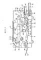
- the optical system (2) includes a light source (21), No. 1 reflector (22) having a concave reflecting surface, No. 2 reflector (23), No. 3 reflector (24), No. 4 reflector (25) , (26) a focusing device comprising a lens etc. and No. 5 reflector (27), wherein the light source (21), No. 1 reflector (22) and No.2 reflector (23) reciprocate once in every copying operation at high speed thereby enable a scanning exposure of the original on the original plate (11) successively, thus the reflected light from the original is irradiated on the surface of the rotary drum (41) to be described after passing through No. 3 reflector (24) and No. 4 reflector (25) which move slowly following the movements of the light source (21), No. 1 reflector (22) and No. 2 reflector (23), the focusing device (26), No. 5 reflector (27) and the slits (28) formed at the fixed positions on the partition plate (15).
- the conveying section (3) for the copying paper comprises the feed rollers (31) (32) which feed the copying paper (P) to a resist roller (34) by taking out from the cassettes (12) (13) one by one, a conveying roller (35) which conveys the copying paper (P) from the resist roller (34) to the copy treatment section (4), a belt (36) which conveys the copying paper (P) separated from the copy treatment section (4), a heat fusing roller (37) which heats and fuses a toner image on the copying paper (P) and a delivery roller (38) which delivers the copying paper (P) heated and fixed to a copy receiving tray (14), wherein the copying paper (P) in the desired cassettes (12) or (13) may be fed one by one by driving the feed rollers (31) (32) selectively.
- the copy treatment section (4) is provided at an approximately center portion in the lower chamber (17), wherein the rotary drum (41) which rotates by a fixed number of rotations in one direction (a direction shown by the arrow Al in the drawing) in every copying operation is installed with an electrostatic charger (42), a developing means (43), a transfer charger (44), a separation charger (45) and a cleaner (46) being arranged in the peripheral thereof in that order.
- one copying operation may be accomplished by forming the electrostatic latent image corresponds to an original image by the irradiated light through the slit (28) after the photoreceptor on the outer surface of the rotary drum (41) being charged uniformly by the electrostatic charger (42), forming the toner image by absorbing the toner by the developing means (43), transfering the toner image on the copying paper (P) fed from the feeding roller (35) by the transfer charger (44), separating the copying paper (P) from the rotary drum (41) by the separation charger (45) and finally recovering the toner remained on the outer surface of the rotary drum (41) by the cleaner (46).
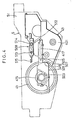
- the developing means (43) comprises a developing housing (401) which includes a magnetic brush mechanism (402), a guide member (406) for developer and an agitating mechanism (407) for developer, and a supplier (408) for the toner particles attached to the.. upper part thereof.
- the magnetic brush mechanism (402) aforementioned is provided adjacent to the external photoreceptor layer (400) on the rotary drum (41) and comprising a cylindrical sleeve member (403) rotatably driven in a direction shown by the arrow A2 having a roll-shaped static permanent magnet (404) arranged therein. Further, a thickness setting member (405) which suspends toward the magnetic brush mechanism (402) and appropriately sets a thickness of the developer layer magnetically retained on the outer surface of the sleeve member (403) is formed on the upper part of the developing housing (401).
- the guide member (406) for the developer drops the developer peeled from the sleeve member (402) by the thickness setting member (405) to the agitating member (407) for the developer located at the rear side (right side in Fig. 2) of the magnetic brush mechanism (402).
- a toner discharge-port (411) is formed at the lower portion of the supplier body (409) having a cover (410) at the upper portion thereof, a toner particles supply roller (412) formed by a porous material such as a sponge etc.
- a numeral (5) is the supporting frame body provided in the lower chamber (17) of the copying machine body (1) which can be drawn out through the vertical front plate (18) (ref. Fig. 3), and supporting the rotary drum (41), the developing means (43) and the cleaner (-46) keeping the accurate relative positions mutually.
- the supporting frame body (5) comprises a front supporting wall (51) and a rear supporting wall (52) connected by the horizontal members (53) (53), wherein the engagement thereof is made possible for drawal and pushing-in by slidably engaging the horizontal members (53) (53) with the guide rails (54) (54) engaged slidably with the guide rails (not illustrated) provided in the lower chamber (17) of the copying machine body (1).
- a numeral (56) is a handle provided on the front supporting wall (51).
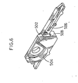
- the supporting members (501) (502) facing each other are Mounted at the center portions of the front supporting wall (51) and the rear supporting wall (52) of the supporting frame body (5) by screwing etc., the bearing member (415) (416) mounted on the bosses (413) (414) extending outwardly in an axial direction of the rotary drum (41) are supported by the cradles (503) (504) having a semicircular shape of each supporting members (501) (502), whereby the rotary drum (41) is positioned freely rotatably.
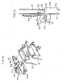
- the vertical position of the developing means (43) against the rotary drum (41) may be accurately controlled and the developing means (43) may be moved to and from the rotary drum (41) along the guide grooves (505) (506) by engaging the plate protruded portions (417) (418) protruded from the front and rear walls of the developing housing (401) with the guide grooves (505) (506) arranged at the fixed position of the supporting members (501) (502) aforementioned adjacent to the cradles (503) (504).
- the movement of the developing means (43) to the side of the rotary drum (41) is prevented and the relative position between the two is maintained accurately by contacting the contact surfaces (507) (508) formed at the fixed position on the supporting members (501) (502) to the contact edges (419) (420) formed respectively at the front and rear walls of the developing housing (401).
- each supporting member (501) (502) the engagement members (509) (In the drawing, only a side mounted to the front supporting wall (51) is shown) are mounted slidably and rotatably in a downward direction.
- a concave (511) as an engagement part is formed which engages with an engagement pin (421) as the engagement part protruded from the front wall of the developing means (43) at the upper fixed position of the main body (510) having a fixed length and extending horizontally.
- An axis (513) of the engagement member (509) is mounted on an approximately hook-shaped aperture (512) formed on the front supporting wall (51) of the supporting frame body (5) slidably and rotatably, whereas a control axis (514) is mounted slidably thereto.
- the engagement member (509) is movable toward the rotary drum (41) by the spring (515) with the rotating condition about the axis (513) to the upward by engaging the bent side of the hook-shaped aperture (512) with the control axis (514) and the other side with the axis (513), further it may rotate downwardly about the axis (513) with the sliding condition opposing the spring (515).
- the vertical relative position between the supporting member (501) and the engagement member (509) is set in such a way that the concave (511) may engage with the engagement pin (421) by rotating the engagement member (509) upward with the engagement of the protruded plate portion (417) with the guide groove (505).
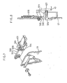
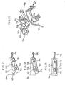
- the engagement pin (421) contacts the concave (511) by rotating the engagement member (509) upwardly about the axis (513) with the engagement pin (421) positioned just above the concave (511) of the engagement member (509) (ref. Fig. 10) by engaging the protruded plate portions (417) (418) of the developing means (43) with the guide grooves (505) (506) and by moving it toward the rotary drum (41) (ref. Fig. 9), whereby the engagement member (509) and the developing means (43) may be moved toward the rotary drum (41) by the spring (515) (ref. Fig. 11).
- the relative positions of the developing means (43) and the rotary drum (41) may be maintained accurately.
- Fig. 12 to Fig. 14 are the drawings showing a mounting operation of the developing means in another embodiment which differ from the embodiment in Fig. 9 to Fig 11 in that, a lever (516) which engages with the engagement pin (421) and rotates when the developing means (43) slides is provided together with an operation axis (517) being formed at the fixed position thereof which rotates the engagement member (509) upwardly with the rotation of the lever (516).
- the engagement pin (421) contacts the lever (516) (ref. Fig. 12) by engaging the protruded plate portion (417) (418) of the developing means (43) respectively with the guide grooves (505) (506) and by moving it toward the rotary drum (41), when being moved further, the operation axis (517) rotates the engagement member (509) anti-clockwise upwardly about the axis (513) by the anti-clockwise rotation of the lever (516) by the engagement pin (421) (ref. Fig.
- the developing means (43) may be mounted without manually rotating the engagement member (509) upwardly by stopping it during the mounting which enables the further improvement of the mounting operation of the developing means (43).
- Fig : . ,15 to Fig. 19 are drawings showing the engagement mechanism of the developing means in another embodiment, which differ from the above embodiment in that, a handle (514 a) extending to the opposite-side of the axis (513) is formed at the end portion of the control axis (514) having a common press-down control part with the handle (514a) to the rear supporting wall (52), while an opening (19a) extending laterally is formed on the vertical rear plate (19) of the copying machine body (1), wherein a shape of the opening (19a) has such a configuration that the handle (514a) may be inserted therethrough only when the engagement member (509) faces properly with the handle (514a) aforementioned only when rotating upwardly.
- the engagement of the developing means (43) may be accomplished as simply and accurately as the embodiment aforementioned.
- the positioning at the fixed set position may be accomplished by pushing in the supporting frame body (5) and inserting the handle (514a) through the opening (19a), on the other hand, at the dismounting condition of the developing (509) means (43), since the engagement member has rotated downwardly and the handle (514a) is in a relative position with the opening (19a) as if being rotated by a fixed angle, when the supporting frame body (5) is pushed, the handle (514a) will be not inserted through the opening (19a) but contacts the rear vertical plate (19) thus the further advance to the fixed set position may be surely prevented.
- the supporting frame body (5) may be pushed in as far as the fixed set position only when the developing means (43) has been set, accordingly the copy operation under the non-setting condition of the developing means will be prevented surely by the limit switch etc. unillustrated which detects the full insertion to the fixed set position. Further, since the handle (514a) is protruded in the front and rear side of the supporting frame body (5) it is easy to handle and the engagement operation is extremely simple.
- Fig. 20 is an exploded perspective view showing a relation between the rear supporting wall of the supporting frame body and the engagement member in another embodiment which differs from the embodiment in Fig. 15 to Fig. 19 in that, the handle (514a) may contact a peripheral of the opening (55) of the front vertical plate (18) by extending the handle (514a) of the engagement member (509) mounted on the side of the rear supporting wall (52) lengthily toward the axis (513) in contrast with the above embodiment and the opening (19a) in the rear vertical plate (19) being omitted.
- the supporting frame body (5) can hardly be pushed in when the developing means is not set and the non-setting thereof may be distinguished immediately at a glance, moreover a damage to the handle (514a) caused by the strong impact given by the inertia may be also prevented since the moving distance of the supporting frame body (5) is small.
- the present invention is not limited to the above embodiment, it may , for instance, be possible to provide the engagement member (509) with a spring which gives constant impetus to rotate upwardly or to arrange the lever (516) which engages with the engagement pin and rotates in the configuration.
- the present invention enables to simplify the engagement of the developing means by eliminating the screwing and the operation for retaining the developing means at the fixed position during the screwing, since the vertical positioning of the developing means is set by the guide which controls the vertical position against the rotary drum and the developing means is slidable toward the rotary drum by the spring with the engagement member rotated to the standard position engaging the engagement pin.
- the engagement of the developing means may be further simplified by eliminating the trouble to rotate the engagement member when it is arranged to rotate following the setting of the developing means.
Landscapes
- Physics & Mathematics (AREA)
- General Physics & Mathematics (AREA)
- Engineering & Computer Science (AREA)
- Computer Vision & Pattern Recognition (AREA)
- Dry Development In Electrophotography (AREA)
- Electrophotography Configuration And Component (AREA)
Applications Claiming Priority (4)
| Application Number | Priority Date | Filing Date | Title |
|---|---|---|---|
| JP225239/83 | 1983-11-28 | ||
| JP58225239A JPS60115966A (ja) | 1983-11-28 | 1983-11-28 | 現像装置脱着機構 |
| JP59181136A JPS6159375A (ja) | 1984-08-30 | 1984-08-30 | 静電式複写機における現像装置脱着機構 |
| JP181136/84 | 1984-08-30 |
Publications (3)
| Publication Number | Publication Date |
|---|---|
| EP0144056A2 true EP0144056A2 (fr) | 1985-06-12 |
| EP0144056A3 EP0144056A3 (en) | 1986-01-15 |
| EP0144056B1 EP0144056B1 (fr) | 1989-02-01 |
Family
ID=26500424
Family Applications (1)
| Application Number | Title | Priority Date | Filing Date |
|---|---|---|---|
| EP84114330A Expired EP0144056B1 (fr) | 1983-11-28 | 1984-11-27 | Système d'embrayage pour le dispositif de développement dans une machine à copier électrostatique |
Country Status (3)
| Country | Link |
|---|---|
| US (1) | US4563074A (fr) |
| EP (1) | EP0144056B1 (fr) |
| DE (1) | DE3476589D1 (fr) |
Cited By (4)
| Publication number | Priority date | Publication date | Assignee | Title |
|---|---|---|---|---|
| DE3608272A1 (de) * | 1986-03-12 | 1987-09-17 | Eisbein Develop | Kopiergeraet |
| FR2652169A1 (fr) * | 1989-09-16 | 1991-03-22 | Canon Kk | Cartouche de traitement a monter de maniere amovible sur un appareil de formation d'images. |
| EP0365056A3 (fr) * | 1985-07-02 | 1991-11-27 | Fujitsu Limited | Dispositif de développement pour appareil d'impression électrophotographique |
| EP0366113A3 (fr) * | 1988-10-28 | 1992-06-10 | Mita Industrial Co., Ltd. | Dispositif de formation d'images |
Families Citing this family (20)
| Publication number | Priority date | Publication date | Assignee | Title |
|---|---|---|---|---|
| DE3532234A1 (de) * | 1984-09-11 | 1986-03-20 | Sharp K.K., Osaka | Elektrophotographisches kopiergeraet |
| US4952989A (en) * | 1985-04-16 | 1990-08-28 | Sharp Kabushiki Kaisha | Photoreceptor attachment device for an electrophotographic copying machine |
| JPS629383A (ja) * | 1985-07-05 | 1987-01-17 | Sharp Corp | 画像形成装置 |
| JPH0795209B2 (ja) * | 1985-11-30 | 1995-10-11 | 三田工業株式会社 | 現像装置 |
| JPS62156671A (ja) * | 1985-12-27 | 1987-07-11 | Sharp Corp | 画像形成装置のカ−トリツジ装置 |
| DE3684269D1 (de) * | 1985-12-27 | 1992-04-16 | Sharp Kk | Photorezeptorkassette. |
| JPS62272283A (ja) * | 1986-05-20 | 1987-11-26 | Sharp Corp | 画像形成装置 |
| DE3770338D1 (de) * | 1986-06-06 | 1991-07-04 | Sharp Kk | Bilderzeugungsgeraet. |
| US4866482A (en) * | 1986-10-24 | 1989-09-12 | Ricoh Company, Ltd. | Image forming device for electrostatic recording apparatus having a slidable replacement holding case |
| USRE34344E (en) * | 1986-11-28 | 1993-08-17 | Mita Industrial Co., Ltd. | Developing device |
| US4851873A (en) * | 1986-11-28 | 1989-07-25 | Mita Industrial Co., Ltd. | Developing device |
| JPH02251869A (ja) * | 1989-03-24 | 1990-10-09 | Toshiba Corp | 電子写真記録装置 |
| US5828928A (en) * | 1990-04-27 | 1998-10-27 | Canon Kabushiki Kaisha | Process cartridge mountable in an image forming system and a method for assembling a cleaning device |
| US5881341A (en) * | 1997-11-14 | 1999-03-09 | Xerox Corporation | Printing cartridge with molded cantilever developer roller spacing spring |
| US6330410B1 (en) * | 1999-02-26 | 2001-12-11 | Brother Kogyo Kabushiki Kaisha | Photosensitive member cartridge |
| EP2110717A3 (fr) | 1999-02-26 | 2013-11-20 | Brother Kogyo Kabushiki Kaisha | Cartouche d'élément photosensible |
| JP4737349B2 (ja) * | 1999-02-26 | 2011-07-27 | ブラザー工業株式会社 | 画像形成装置 |
| KR100395523B1 (ko) * | 2001-01-19 | 2003-08-25 | 삼성전자주식회사 | 레이저 프린터 |
| US6907216B2 (en) * | 2001-12-04 | 2005-06-14 | Kyocera Corporation | Image forming apparatus having a roll supporting member |
| US20040091120A1 (en) * | 2002-11-12 | 2004-05-13 | Kantor Kenneth L. | Method and apparatus for improving corrective audio equalization |
Citations (1)
| Publication number | Priority date | Publication date | Assignee | Title |
|---|---|---|---|---|
| JPS58181058A (ja) | 1982-04-19 | 1983-10-22 | Mita Ind Co Ltd | 静電複写機 |
Family Cites Families (6)
| Publication number | Priority date | Publication date | Assignee | Title |
|---|---|---|---|---|
| DE2729349C3 (de) * | 1977-06-29 | 1981-06-25 | Agfa-Gevaert Ag, 5090 Leverkusen | Elektrostatisches Kopiergerät |
| US4345834A (en) * | 1978-11-02 | 1982-08-24 | Mita Industrial Company Limited | Transfer type electrostatic copying apparatus |
| JPS56122049A (en) * | 1980-02-29 | 1981-09-25 | Toshiba Corp | Electronic copier |
| US4327992A (en) * | 1980-07-10 | 1982-05-04 | Apeco Corporation | Driving arrangement for photocopy machine |
| US4470689A (en) * | 1981-06-02 | 1984-09-11 | Canon Kabushiki Kaisha | Image forming apparatus and process unit |
| US4462677A (en) * | 1981-06-22 | 1984-07-31 | Canon Kabushiki Kaisha | Image formation apparatus using a process unit with a protective cover |
-
1984
- 1984-11-27 US US06/675,170 patent/US4563074A/en not_active Expired - Lifetime
- 1984-11-27 DE DE8484114330T patent/DE3476589D1/de not_active Expired
- 1984-11-27 EP EP84114330A patent/EP0144056B1/fr not_active Expired
Patent Citations (1)
| Publication number | Priority date | Publication date | Assignee | Title |
|---|---|---|---|---|
| JPS58181058A (ja) | 1982-04-19 | 1983-10-22 | Mita Ind Co Ltd | 静電複写機 |
Cited By (7)
| Publication number | Priority date | Publication date | Assignee | Title |
|---|---|---|---|---|
| EP0365056A3 (fr) * | 1985-07-02 | 1991-11-27 | Fujitsu Limited | Dispositif de développement pour appareil d'impression électrophotographique |
| EP0369494A3 (fr) * | 1985-07-02 | 1991-11-27 | Fujitsu Limited | Appareil d'impression électrophotographique |
| DE3608272A1 (de) * | 1986-03-12 | 1987-09-17 | Eisbein Develop | Kopiergeraet |
| EP0366113A3 (fr) * | 1988-10-28 | 1992-06-10 | Mita Industrial Co., Ltd. | Dispositif de formation d'images |
| FR2652169A1 (fr) * | 1989-09-16 | 1991-03-22 | Canon Kk | Cartouche de traitement a monter de maniere amovible sur un appareil de formation d'images. |
| US5151734A (en) * | 1989-09-16 | 1992-09-29 | Canon Kabushiki Kaisha | Process cartridge detachably mountable to image forming apparatus featuring a peripherally supported image bearing drum |
| EP0419122A3 (en) * | 1989-09-16 | 1992-09-30 | Canon Kabushiki Kaisha | Image forming apparatus |
Also Published As
| Publication number | Publication date |
|---|---|
| US4563074A (en) | 1986-01-07 |
| DE3476589D1 (en) | 1989-03-09 |
| EP0144056A3 (en) | 1986-01-15 |
| EP0144056B1 (fr) | 1989-02-01 |
Similar Documents
| Publication | Publication Date | Title |
|---|---|---|
| US4563074A (en) | Engagement mechanism for a developing means in electrostatic copying machine | |
| EP2157486B1 (fr) | Cartouche et appareil de formation d'images électro-photographiques | |
| US6041203A (en) | Process unit, photosensitive member cartridge, developer cartridge, and image forming apparatus | |
| US5095335A (en) | Copier with retractable charging unit to prevent damage to drum when removing process cartridge | |
| US8391747B2 (en) | Process cartridge and image forming apparatus having the same | |
| US5105221A (en) | Image forming apparatus having detachable optical and processing units | |
| US6980756B2 (en) | Process cartridge, electrophotographic image forming apparatus, and process cartridge mounting system | |
| US4841330A (en) | Recording apparatus | |
| JP2659717B2 (ja) | 画像形成装置における作像ユニット着脱装置 | |
| US6920297B2 (en) | Image forming apparatus that cleans a wire of a charger | |
| US5862441A (en) | Image-forming machine | |
| JPS62209546A (ja) | 電子写真装置 | |
| JPS5825650A (ja) | 画像形成装置 | |
| JPH10115961A (ja) | 画像形成装置 | |
| JP2551535B2 (ja) | 画像形成装置 | |
| JPH0123140Y2 (fr) | ||
| JPH11301059A (ja) | 画像形成装置 | |
| JPH09190134A (ja) | プロセスカートリッジ及び画像形成装置 | |
| JPH07181871A (ja) | 画像形成装置のための着脱自在なユニット | |
| JP2026067702A (ja) | プロセスユニット及び画像形成装置 | |
| JP2782205B2 (ja) | クリーニングユニット | |
| KR0115049Y1 (ko) | 드럼표면의 손상을 방지하는 드럼장착장치 | |
| KR930012270B1 (ko) | 화상 형성장치 | |
| JPH043548B2 (fr) | ||
| JPS63109477A (ja) | 画像生成機のための現像装置 |
Legal Events
| Date | Code | Title | Description |
|---|---|---|---|
| PUAI | Public reference made under article 153(3) epc to a published international application that has entered the european phase |
Free format text: ORIGINAL CODE: 0009012 |
|
| AK | Designated contracting states |
Designated state(s): DE FR GB NL |
|
| PUAL | Search report despatched |
Free format text: ORIGINAL CODE: 0009013 |
|
| AK | Designated contracting states |
Designated state(s): DE FR GB NL |
|
| 17P | Request for examination filed |
Effective date: 19860502 |
|
| 17Q | First examination report despatched |
Effective date: 19870901 |
|
| GRAA | (expected) grant |
Free format text: ORIGINAL CODE: 0009210 |
|
| AK | Designated contracting states |
Kind code of ref document: B1 Designated state(s): DE FR GB NL |
|
| REF | Corresponds to: |
Ref document number: 3476589 Country of ref document: DE Date of ref document: 19890309 |
|
| ET | Fr: translation filed | ||
| PLBE | No opposition filed within time limit |
Free format text: ORIGINAL CODE: 0009261 |
|
| STAA | Information on the status of an ep patent application or granted ep patent |
Free format text: STATUS: NO OPPOSITION FILED WITHIN TIME LIMIT |
|
| 26N | No opposition filed | ||
| PGFP | Annual fee paid to national office [announced via postgrant information from national office to epo] |
Ref country code: FR Payment date: 19951109 Year of fee payment: 12 |
|
| PGFP | Annual fee paid to national office [announced via postgrant information from national office to epo] |
Ref country code: GB Payment date: 19951120 Year of fee payment: 12 |
|
| PGFP | Annual fee paid to national office [announced via postgrant information from national office to epo] |
Ref country code: DE Payment date: 19951128 Year of fee payment: 12 |
|
| PGFP | Annual fee paid to national office [announced via postgrant information from national office to epo] |
Ref country code: NL Payment date: 19951129 Year of fee payment: 12 |
|
| PG25 | Lapsed in a contracting state [announced via postgrant information from national office to epo] |
Ref country code: GB Effective date: 19961127 |
|
| PG25 | Lapsed in a contracting state [announced via postgrant information from national office to epo] |
Ref country code: NL Effective date: 19970601 |
|
| GBPC | Gb: european patent ceased through non-payment of renewal fee |
Effective date: 19961127 |
|
| PG25 | Lapsed in a contracting state [announced via postgrant information from national office to epo] |
Ref country code: FR Effective date: 19970731 |
|
| NLV4 | Nl: lapsed or anulled due to non-payment of the annual fee |
Effective date: 19970601 |
|
| PG25 | Lapsed in a contracting state [announced via postgrant information from national office to epo] |
Ref country code: DE Effective date: 19970801 |
|
| REG | Reference to a national code |
Ref country code: FR Ref legal event code: ST |